torque GEELY FC 2008 Repair Manual
[x] Cancel search | Manufacturer: GEELY, Model Year: 2008, Model line: FC, Model: GEELY FC 2008Pages: 419, PDF Size: 13.87 MB
Page 153 of 419
Brake--Front brake assembly13. Check the brake branch pump and pistonCheck whether there is rust or scratch in cylinder of branch
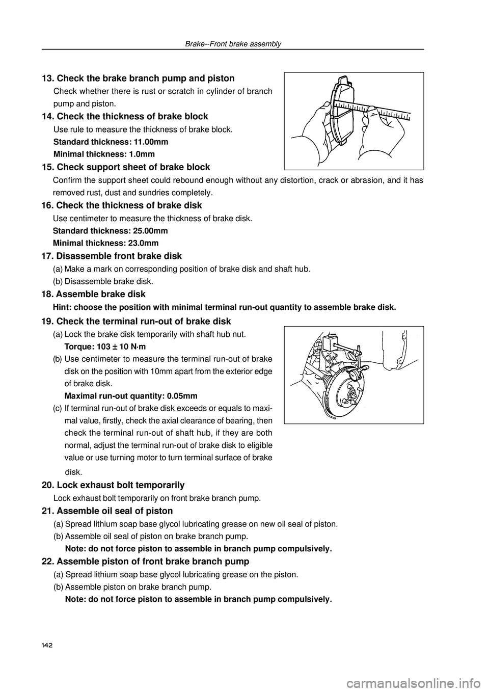
pump and piston.14. Check the thickness of brake blockUse rule to measure the thickness of brake block.
Standard thickness: 11.00mm
Minimal thickness: 1.0mm15. Check support sheet of brake block
142Confirm the support sheet could rebound enough without any distortion, crack or abrasion, and it has
removed rust, dust and sundries completely.16. Check the thickness of brake diskUse centimeter to measure the thickness of brake disk.
Standard thickness: 25.00mm
Minimal thickness: 23.0mm17. Disassemble front brake disk(a) Make a mark on corresponding position of brake disk and shaft hub.
(b) Disassemble brake disk.18. Assemble brake diskHint: choose the position with minimal terminal run-out quantity to assemble brake disk.19. Check the terminal run-out of brake disk(a) Lock the brake disk temporarily with shaft hub nut.
Torque: 103
± ± ± ±
± 10 N
⋅ ⋅⋅ ⋅
⋅m
(b) Use centimeter to measure the terminal run-out of brake
disk on the position with 10mm apart from the exterior edge
of brake disk.
Maximal run-out quantity: 0.05mm
(c) If terminal run-out of brake disk exceeds or equals to maxi-
mal value, firstly, check the axial clearance of bearing, then
check the terminal run-out of shaft hub, if they are both
normal, adjust the terminal run-out of brake disk to eligible
value or use turning motor to turn terminal surface of brake
disk.20. Lock exhaust bolt temporarilyLock exhaust bolt temporarily on front brake branch pump.21. Assemble oil seal of piston(a) Spread lithium soap base glycol lubricating grease on new oil seal of piston.
(b) Assemble oil seal of piston on brake branch pump.
Note: do not force piston to assemble in branch pump compulsively.22. Assemble piston of front brake branch pump(a) Spread lithium soap base glycol lubricating grease on the piston.
(b) Assemble piston on brake branch pump.
Note: do not force piston to assemble in branch pump compulsively.
Page 154 of 419
Brake--Front brake assembly23.Assemble dustproof cover of branch pump..(a) After spreading lithium soap base glycol lubricating grease
on new dustproof cover of branch pump, assembling it in
brake branch pump.
Hint: dustproof cover should be assembled in branch
pump firmly.
(b) Use wrench to assemble fixing loop.
Note: do not damage dustproof cover.24. Assemble brake branch pump bracket.Use two bolts to assemble brake branch pump bracket.
Torque: 106
± ±± ±
± 10 N
⋅ ⋅⋅ ⋅
⋅m25. Assemble dustproof cover of brake branch pump
bracket.(a) Spread lithium soap base glycol lubricating grease on new
dustproof cover.
(b) Assemble two dustproof covers in front brake branch pump
bracket.26. Assemble sliding pin of front brake branch pump.(a) Spread lithium soap base glycol lubricating grease on the
surface of sliding part and sliding pin.
(b) Assemble two sliding pins in front brake branch pump
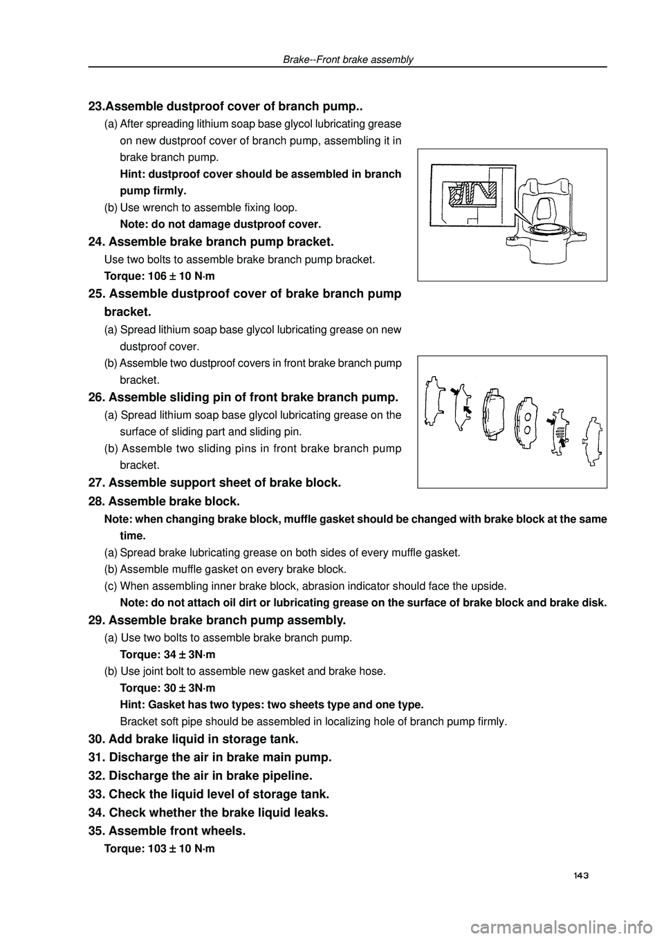
bracket.27. Assemble support sheet of brake block.143 28. Assemble brake block.Note: when changing brake block, muffle gasket should be changed with brake block at the same
time.
(a) Spread brake lubricating grease on both sides of every muffle gasket.
(b) Assemble muffle gasket on every brake block.
(c) When assembling inner brake block, abrasion indicator should face the upside.
Note: do not attach oil dirt or lubricating grease on the surface of brake block and brake disk.29. Assemble brake branch pump assembly.(a) Use two bolts to assemble brake branch pump.
Torque: 34
± ±± ±
± 3N
⋅ ⋅⋅ ⋅
⋅m
(b) Use joint bolt to assemble new gasket and brake hose.
Torque: 30
± ±± ±
± 3N
⋅ ⋅⋅ ⋅
⋅m
Hint: Gasket has two types: two sheets type and one type.
Bracket soft pipe should be assembled in localizing hole of branch pump firmly.30. Add brake liquid in storage tank.
31. Discharge the air in brake main pump.
32. Discharge the air in brake pipeline.
33. Check the liquid level of storage tank.
34. Check whether the brake liquid leaks.
35. Assemble front wheels.Torque: 103
± ±± ±
± 10 N
⋅ ⋅⋅ ⋅
⋅m
Page 156 of 419
Brake--Rear brake assemblyUse screw driver to disassemble oil seal of piston from brake
branch pump.
Note: do not damage cylinder wall and slot.10. Disassemble exhaust bolt of branch pump.
11. Check whether there is any dust or scratch on
branch pump and piston.
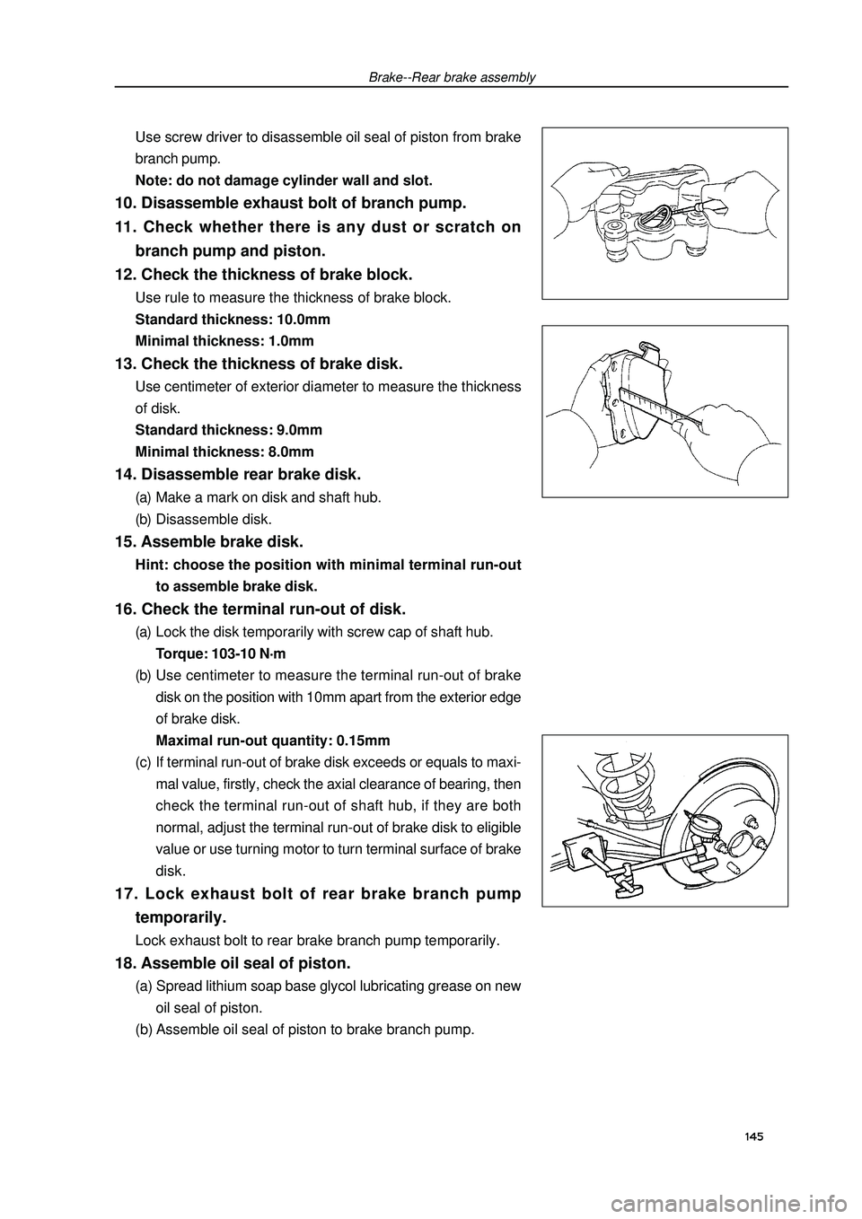
12. Check the thickness of brake block.Use rule to measure the thickness of brake block.
Standard thickness: 10.0mm
Minimal thickness: 1.0mm13. Check the thickness of brake disk.Use centimeter of exterior diameter to measure the thickness
of disk.
Standard thickness: 9.0mm
Minimal thickness: 8.0mm14. Disassemble rear brake disk.(a) Make a mark on disk and shaft hub.
(b) Disassemble disk.15. Assemble brake disk.Hint: choose the position with minimal terminal run-out
to assemble brake disk.16. Check the terminal run-out of disk.(a) Lock the disk temporarily with screw cap of shaft hub.
Torque: 103-10 N
⋅ ⋅⋅ ⋅
⋅m
(b) Use centimeter to measure the terminal run-out of brake
disk on the position with 10mm apart from the exterior edge
of brake disk.
Maximal run-out quantity: 0.15mm
(c) If terminal run-out of brake disk exceeds or equals to maxi-
mal value, firstly, check the axial clearance of bearing, then
check the terminal run-out of shaft hub, if they are both
normal, adjust the terminal run-out of brake disk to eligible
value or use turning motor to turn terminal surface of brake
disk.17. Lock exhaust bolt of rear brake branch pump
temporarily.Lock exhaust bolt to rear brake branch pump temporarily.18. Assemble oil seal of piston.(a) Spread lithium soap base glycol lubricating grease on new
oil seal of piston.
(b) Assemble oil seal of piston to brake branch pump.145
Page 157 of 419

Brake--Rear brake assembly19. Assemble piston of Rear brake branch pump(a) Spread lithium soap base glycol lubricating grease on the
piston.
(b) Assemble piston on brake branch pump.
Note: do not force piston to assemble in branch pump
compulsively.20. Assemble dustproof cover of branch pump.(a) Spread lithium soap base glycol lubricating grease on new
dustproof cover of branch pump.
(b) Assemble dustproof cover in brake branch pump.
Hint: dustproof cover should be assembled in branch
pump firmly.
(c) Use screw driver to assemble fixing loop.
Note: do not damage dustproof cover.21. Assemble dustproof bushing of rear brake.(a) Spread lithium soap base glycol lubricating grease on the
surface of three dustproof bushings.
(b) Assemble three dustproof bushings in brake branch pump.22. Assemble the bushing of brake branch pump
bracket.Assemble two bushings of brake branch pump bracket.23. Assemble brake branch pump.(a) Assemble branch pump with two bolts.
Torque: 47
± ±± ±
± 4N
⋅ ⋅⋅ ⋅
⋅m
(b) Assemble new gasket and brake hose with joint bolt.
Torque: 30
± ±± ±
± 3N
⋅ ⋅⋅ ⋅
⋅m
Hint:�zGasket has two types: two sheets type and one
sheet type.�zBrake soft pipe should be assembled in localizing
hole of branch pump firmly.146Brake branch pump
Dustproof cover
Dustproof cover
Brake branch pump
Page 158 of 419
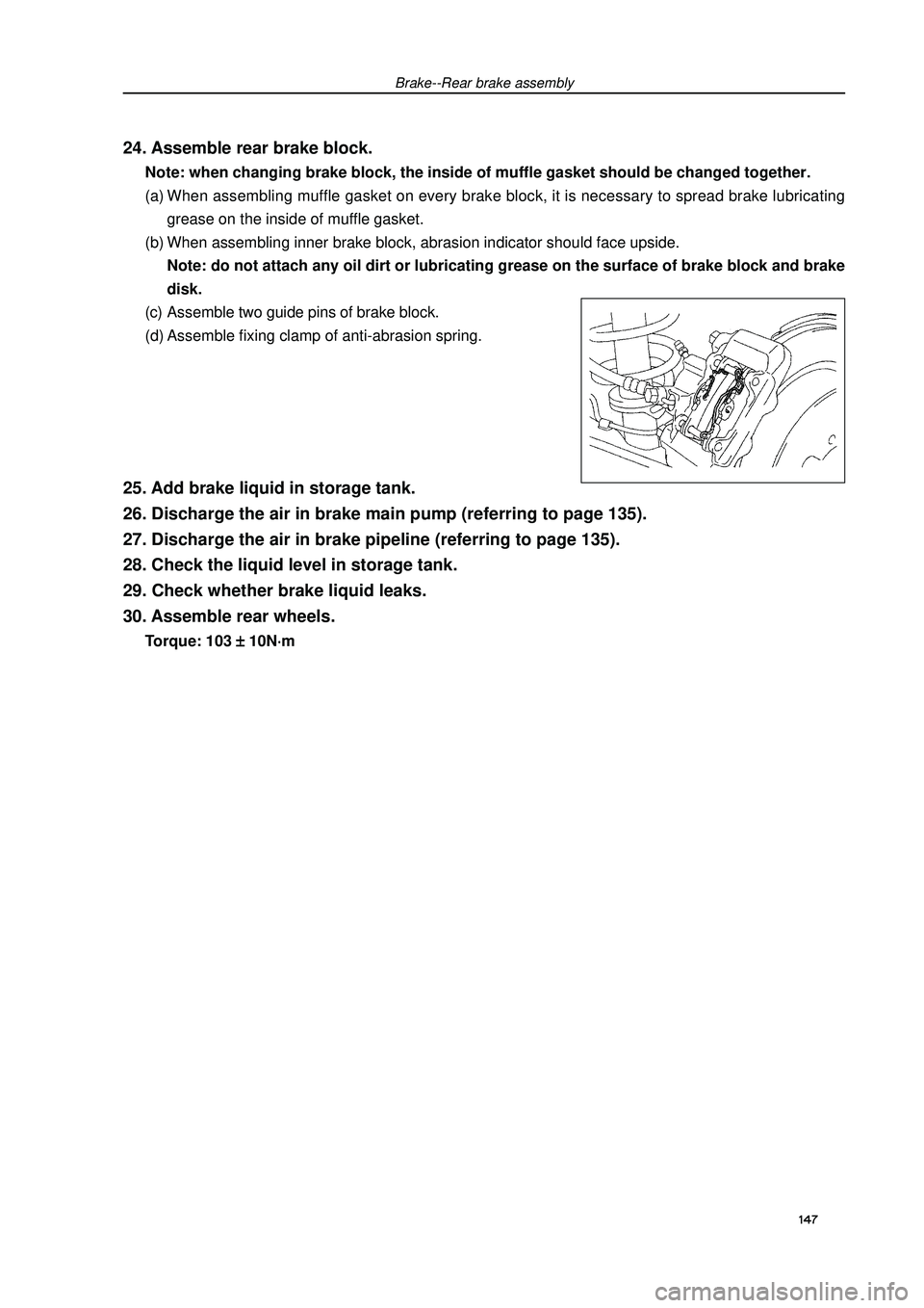
Brake--Rear brake assembly24. Assemble rear brake block.Note: when changing brake block, the inside of muffle gasket should be changed together.
(a) When assembling muffle gasket on every brake block, it is necessary to spread brake lubricating
grease on the inside of muffle gasket.
(b) When assembling inner brake block, abrasion indicator should face upside.
Note: do not attach any oil dirt or lubricating grease on the surface of brake block and brake
disk.
(c) Assemble two guide pins of brake block.
(d) Assemble fixing clamp of anti-abrasion spring.25. Add brake liquid in storage tank.
26. Discharge the air in brake main pump (referring to page 135).
27. Discharge the air in brake pipeline (referring to page 135).
28. Check the liquid level in storage tank.
29. Check whether brake liquid leaks.
30. Assemble rear wheels.Torque: 103
± ±± ±
± 10N
⋅ ⋅⋅ ⋅
⋅m147
Page 160 of 419

Brake--Hydraulic pressure control unit3. Disassemble gasket of right wheel wing.
4. Disassemble hydraulic control unit and bracket.(a) Disassemble the joint and bolt.
(b) Turn the locking bolt of joint of hydraulic control unit, and
disassemble the joint.
(c) Use special tool to disassemble the brake oil pipe on hy-
draulic control unit.
(d) Use label to mark the name of every oil pipe, and tie it on
oil pipe.
(e) Disassemble screw caps, two bolts and hydraulic control
unit and bracket.5. Disassemble hydraulic control unit assembly.Disassemble three bolts and hydraulic control unit from the bracket.6. Assemble hydraulic control unit assembly.Assemble three bolts and hydraulic control unit on the bracket with three bolts.
Torque: 4.7 N
⋅ ⋅⋅ ⋅
⋅m149Connect the front
of main cylinder
Connect the back
of main cylinder
Connect 2#
brake pipe
Connect the front left
Connect 2#
brake pipeConnect the front right
Page 161 of 419
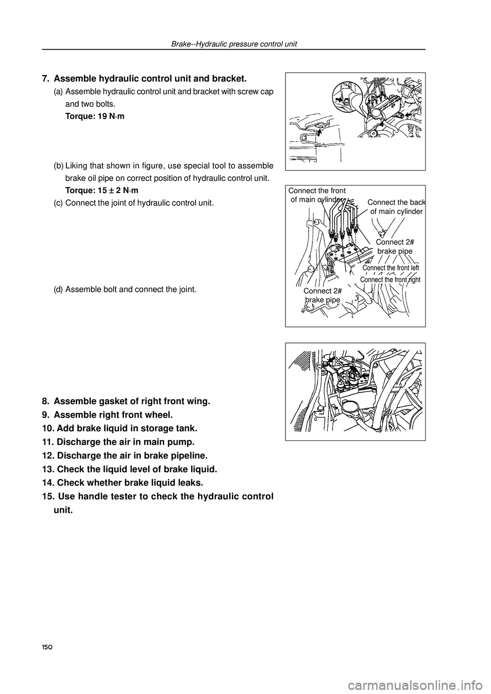
Brake--Hydraulic pressure control unit7. Assemble hydraulic control unit and bracket.(a) Assemble hydraulic control unit and bracket with screw cap
and two bolts.
Torque: 19 N
⋅ ⋅⋅ ⋅
⋅m
(b) Liking that shown in figure, use special tool to assemble
brake oil pipe on correct position of hydraulic control unit.
Torque: 15
± ±± ±
± 2 N
⋅ ⋅⋅ ⋅
⋅m
(c) Connect the joint of hydraulic control unit.
(d) Assemble bolt and connect the joint.8. Assemble gasket of right front wing.
9. Assemble right front wheel.
10. Add brake liquid in storage tank.
11. Discharge the air in main pump.
12. Discharge the air in brake pipeline.
13. Check the liquid level of brake liquid.
14. Check whether brake liquid leaks.
15. Use handle tester to check the hydraulic control
unit.150Connect the front
of main cylinder
Connect the back
of main cylinder
Connect 2#
brake pipe
Connect the front left
Connect 2#
brake pipeConnect the front right
Page 162 of 419

Brake--Speed sensor of front wheelSpeed sensor of front wheelChangeHint: the process for changing right side is same as the
left side.1. Disassemble front wheels.
2. Disassemble gasket of left front wing.
3. Disassemble speed sensor of left front wheel.(a) Disassemble resinous clamp and speed sensor wiring har-
ness from fixing clamp of automobile body.
(b) Disassemble the sensor joint.
(c) Disassemble two bolts of fixing clamp of sensor wiring har-
ness from automobile body and absorber.
(d) Disassemble bolt and left front sensor.
Note: do not attach any sundries on top of sensor.4. Assemble speed sensor of left front wheel.(a) Use bolt to assemble left front sensor.
Torque: 8.0 N
⋅ ⋅⋅ ⋅
⋅m
Note: do not attach any sundries on top of sensor.
(b) Use two bolts to assemble fixing clamp of sensor wiring
harness on automobile body and absorber.
Bolt A: 9.0 N
⋅ ⋅⋅ ⋅
⋅m
Bolt B: 29 N
⋅ ⋅⋅ ⋅
⋅m
(c) Connect the joint of speed sensor.
(d) Connect resinous clamp and speed sensor wiring harness
on automobile body and fixing clamp.5. Assemble gasket of left front wheel wing.
6. Assemble front wheels.Torque: 103
± ±± ±
± 10 N
⋅ ⋅⋅ ⋅
⋅m7. Check the signal of ABS speed sensor.151
Page 164 of 419

Brake--Speed sensor of rear wheels153(c) Use special tool and press to assemble speed sensor of
rear wheels to rear shaft hub.
Note:�zDo not use hammer knock directly in speed sensor
of rear wheels.�zInsure no sundries are attached on the supervising
part of speed sensor of rear wheels�zPress speed sensor of rear wheels straightly and
slowly.8. Assemble left rear shaft hub and bearing assembly
(referring to page 129).
9. Assemble brake disk.
10. Assemble left rear brake branch pump.
11. Assemble wiring harness of speed sensor of rear
wheels.
12. Assemble rear wheels.Torque: 103
± ±± ±
± 10 N
⋅ ⋅⋅ ⋅
⋅m13. Check and adjust wheel alignment.
14. Check the signal of ABS speed sensor.Special
tool
Page 165 of 419

Parking brakeParking brake systemMalfunction phenomenon tableUse following table to find the reason of malfunction, the number in table indicates the preferred se-
quence of possible reason. Please check each part by sequence, if necessary, change this part.Parking brake--Parking brake systemAdjustment1. Disassemble rear wheels
2. Adjust the clearance of parking brake shoe
3. Assemble rear wheelsTorque: 103
± ±± ±
± 10 N
⋅ ⋅⋅ ⋅
⋅m4. Check the travel of parking brake handle.Pull up the parking brake handle and calculate the sound num-
ber of handle.
When parking brake handle locates 196N: 6-9 sounds.5. Adjust the travel of parking brake handle(a) Disassemble upper trim board of central box.
(b) Disassemble central box.
(c) Release locking screw cap, then rotate adjusting screw cap
until handle travel accords with the specification.
(d) Tighten locking screw cap.
Torque: 5.0 N
⋅ ⋅⋅ ⋅
⋅m
(e) Assemble central box.
(f) Assemble trim board on central box.Malfunction phenomenon Possible malfunction part Reference page
1. Travel of parking brake handle (adjusted badly). 154
2. Pull cable of parking brake (attached).156, 158
Brake lag 3. Clearance of parking brake shoe (adjusted badly). 161
4. Friction plate of parking brake shoe (damaged or distorted). 161
5. Tension or return spring (damaged). 161Lock the screw cap
Adjust the
screw cap154