alternator GEELY FC 2008 Workshop Manual
[x] Cancel search | Manufacturer: GEELY, Model Year: 2008, Model line: FC, Model: GEELY FC 2008Pages: 419, PDF Size: 13.87 MB
Page 7 of 419

Replacement...................................................
72
Coolant.................................................................
73
Replacement...................................................
73
Lubrication
Lubricating system...............................................
74
On-vehicle inspection......................................
74
Oil filter assembly.................................................
75
Replacement....................................................
75
Oil pump assembly...............................................
76
Replacement....................................................
76
Ignition
Ignition system.....................................................
77
Inspection........................................................
77
On-vehicle inspection......................................
77
Starting and charging
Starting system.....................................................
79
Inspection........................................................
79
Charging system..................................................
81
Precautions......................................................
81
On-vehicle inspection......................................
82
Alternator components..............................................
84
Replacement....................................................
84
Starter components..............................................
85
Replacement....................................................
85
Front suspension
Front suspension system....................................
86
Table on trouble occurrence...........................
86
Front wheel alignment.........................................
87
Adjustment......................................................
87
Front absorber and helical spring.......................
90
Overhaul..........................................................
90
Handling..........................................................
93
Lower left control arm assembly.........................
94
Replacement...................................................
94Front stabilizer bar...............................................
96
Overhaul..........................................................
96
Front left lower control arm ball joint assembly
..
99
Replacement...................................................
99
Rear suspension
Rear suspension system....................................
100
Table on trouble occurrence..........................
100
Rear wheel alignment.........................................
101
Adjustment.....................................................
101
Rear strut assembly...........................................
102
Overhaul........................................................
102
Handling.........................................................
104
Rear stabilizer bar..............................................
105
Overhaul........................................................
105
Rear shaft assembly...........................................
106
Overhaul........................................................
106
Tire and wheel
Wheel and tire system.......................................
109
Inspection......................................................
109
Drive shaft
Drive shaft.......................................................
111
Notes.............................................................
111
Malfunction phenomenon table....................
111
Inspection on automobile.............................
11 2
Front drive shaft.................................................
11 3
Overhaul........................................................
11 3
Left front shaft hub assembly............................
123
Change..........................................................
123
Left front shaft hub bolt......................................
128
Change..........................................................
128
Left rear shaft hub and bearing assembly........
129
Change..........................................................
129
Left rear shaft hub bolt.......................................
131
Change..........................................................
131
Page 48 of 419
![GEELY FC 2008 Workshop Manual Engine mechanism - Engine assembly22. Remove drive belt.Drive belt tensioner could turn belt tensioner clockwise to
loosen it.23. Remove alternator mounting components [4G18-
3701100].
24. Remove comp GEELY FC 2008 Workshop Manual Engine mechanism - Engine assembly22. Remove drive belt.Drive belt tensioner could turn belt tensioner clockwise to
loosen it.23. Remove alternator mounting components [4G18-
3701100].
24. Remove comp](/img/58/57161/w960_57161-47.png)
Engine mechanism - Engine assembly22. Remove drive belt.Drive belt tensioner could turn belt tensioner clockwise to
loosen it.23. Remove alternator mounting components [4G18-
3701100].
24. Remove compressor assembly.
25. Remove front chassis bracket.
26. Remove front exhaust pipe assembly.
27. Remove steering middle shaft assembly.(a) Remove steering column seal hole cover.
(b) Make alignment mark on steering middle shaft.
(c) Remove 2 bolts and steering middle shaft.
(d) Remove steering column cover.28. Remove the nuts on left side of front shaft hub.(a) Completely knock out the concave part of fixed nuts with
special tool and hammer.
Notes:Completely knock out the concave part of fixed
nuts before removing the fixed nuts.Do not damage thread of drive shaft.Do not sharpen the sharp end of special tool.Place the special tool in groove with its plane facing
upward.
(b) Remove fixed nuts with socket wrench (30mm).
Hint: perform the same steps at another side.29. Disassemble left side transversal lever assembly.Disassemble transversal lever assembly from steering
knuckle with special tool.
Hint: perform the same steps at another side.Alignment
markSpecial tool
Special tool37Sliding outLifting
Page 55 of 419

Engine mechanism - Engine assembly85. Install alternator mounting components.Torque: 12mm bolt head A: 14mm bolt head B: 86. Install drive belt.
87. Install engine wire harness and all hoses
not connected.(a) Check and connect all joints of engine wire harness.
(b) Check and connect all hoses.88. Install transmission control pull cable assembly
and valve control pull cable.
89. Install air filter assembly and its hose.
90. Install steering middle shaft assembly.(a) Align alignment mark on steering middle shaft.
(b) Install 2 bolts.
Torque: m
(c) Install steering column cover.91. Install front exhaust pipe assembly.
92. Install front chassis bracket.Torque: 93. Install battery and connect wire.
94. Install engine plastic hood components.
95. Install front wheel and engine bottom shield.
96. Refill transmission lubricant.
97. Refill engine oil.
98. Refill coolant.
99. Check there is oil leakage.
100. Check there is coolant leakage.
101. Check idle speed and ignition timing.
102. Check CO/HC.Alignment
mark
Sliding in
Pulling 44
Page 56 of 419

Engine mechanism - Timing chain assemblyTiming chain assemblyReplacement1. Remove engine left bottom shield.
2. Remove engine right bottom shield.
3. Discharge coolant.
4. Remove engine plastic hood components.
5. Remove drive belt.
6. Remove power steering pump assembly.
7. Remove alternator assembly.
8. Uncouple engine wire harness.(a) Remove ignition coil joint, PS fuel pressure switch joint,
fuel line control joint and speed sensor joint.
(b) Remove bolts and nuts of fixed earth wire and put aside
engine wire harness.9. Remove ignition coil assembly.
10. Remove cylinder head cover components.(a) Remove fuel pipe retaining clip and 2 PCV hoses from
cylinder head cover.
(b) Remove 9 bolts, 2 seal washers, cylinder head cover
components and gasket.11. Remove right engine mounting assembly.(a) Remove PS oil pump reservoir and put it aside.
(b) Place wooden block between jack and engine, prop-
erly place the jack, and then remove right engine mount-
ing assembly.12. Turn crankshaft to cylinder 1 compression top
dead center position.
13. Remove damping pulley components
[4G18-1005110].Remove pulley bolts with special tool.
Remove damping pulley components with special tool.Special
tool
Special
tool45
Page 62 of 419

Engine mechanism - Timing chain assembly41. Install alternator mounting components.Torque: 12mm bolt head: 14mm bolt head: m42. Refill coolant.
43. Check there is coolant leakage.
44. Check there is oil leakage.
51
Page 80 of 419

Cooling - Water pump assemblyWater pump assemblyReplacement1. Remove engine right bottom shield.
2. Discharge engine coolant.
3. Remove drive belt.Slowly turn drive belt tensioner clockwise to loosen the belt;
then remove drive belt and put back drive belt tensioner slowly
to completely loosen the tensioner.4. Remove alternator assembly.(a) Remove rubber cover and nuts.
(b) Uncouple alternator joint.
(c) Remove 2 bolts and alternator.5. Remove water pump assembly.Remove 6 bolts, water pump and o-ring.69
Page 81 of 419

Cooling - Water pump assembly6. Install water pump assembly.(a) Install new o-ring on water pump.
(b) Install water pump with 6 bolts.
Torque: bolt A: Bolt B: 7. Install alternator mounting components.Torque: 12mm bolt head: 14mm bolt head: 8. Refill engine coolant.
9. Check there is leakage with coolant.
70
Page 82 of 419

Cooling - Temperature regulator componentsReplacement1. Remove engine right bottom shield.
2. Discharge engine coolant.
3. Remove drive belt.Slowly turn drive belt tensioner clockwise to loosen the belt;
then remove drive belt and put back the tensioner slowly to
completely loosen it.4. Remove alternator components.(a) Remove rubber cover and nuts.
(b) Uncouple alternator joint.
(c) Remove 2 bolts and alternator.5. Remove water inlet pipe.
6. Remove temperature regulator.
7. Install temperature regulator.(a) Install new gasket to temperature regulator.
(b) As shown in the diagram, install temperature regulator with
inching valve toward upward.8. Install water inlet pipe and joint.Torque: 9. Install alternator installation components.Torque: 12mm bolt head: m
14mm bolt head: 10. Refill engine coolant.
11. Check there is leakage with coolant.
71Temperature regulator components
Page 93 of 419

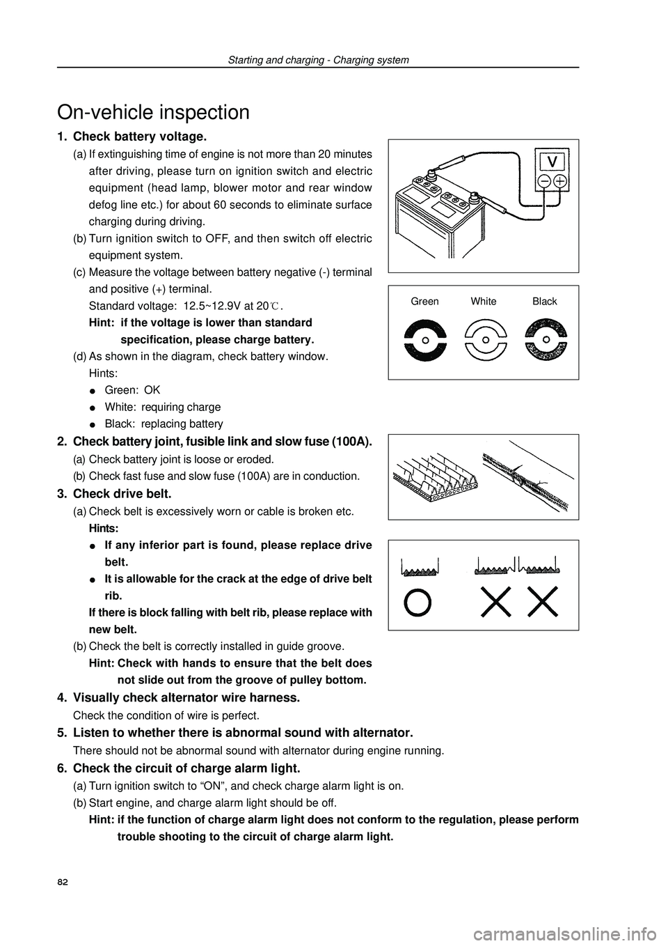
1. Check battery voltage.(a) If extinguishing time of engine is not more than 20 minutes
after driving, please turn on ignition switch and electric
equipment (head lamp, blower motor and rear window
defog line etc.) for about 60 seconds to eliminate surface
charging during driving.
(b) Turn ignition switch to OFF, and then switch off electric
equipment system.
(c) Measure the voltage between battery negative (-) terminal
and positive (+) terminal.
Standard voltage: 12.5~12.9V at 20.
Hint: if the voltage is lower than standard
specification, please charge battery.
(d) As shown in the diagram, check battery window.
Hints:Green: OKWhite: requiring chargeBlack: replacing battery2. Check battery joint, fusible link and slow fuse (100A).(a) Check battery joint is loose or eroded.
(b) Check fast fuse and slow fuse (100A) are in conduction.3. Check drive belt.(a) Check belt is excessively worn or cable is broken etc.
Hints:If any inferior part is found, please replace drive
belt.It is allowable for the crack at the edge of drive belt
rib.
If there is block falling with belt rib, please replace with
new belt.
(b) Check the belt is correctly installed in guide groove.
Hint:Check with hands to ensure that the belt does
not slide out from the groove of pulley bottom.4. Visually check alternator wire harness.Check the condition of wire is perfect.Starting and charging - Charging systemOn-vehicle inspectionGreen White Black5. Listen to whether there is abnormal sound with alternator.There should not be abnormal sound with alternator during engine running.6. Check the circuit of charge alarm light.(a) Turn ignition switch to “ON”, and check charge alarm light is on.
(b) Start engine, and charge alarm light should be off.
Hint: if the function of charge alarm light does not conform to the regulation, please perform
trouble shooting to the circuit of charge alarm light.82
Page 94 of 419

Starting and charging - Charging system7. Check charging system circuit at no load.(a) If there is battery/alternator tester, please connect tester
to charging system circuit as manufacturer instruction.
(b) If there is no battery/alternator tester, please connect volt-
meter to charging system circuit as the following way.
�zUncouple wire on engine terminal B, and connect wire
on negative (-) test bar of ampere meter.
�zConnect positive (+) test bar of ampere meter to alter-
nator terminal B.
�zConnect positive (+) test bar of voltmeter to alternator
terminal B.
�zConnect negative test bar of voltmeter to earth.8. Check charging system circuit at load.(a) Turn on high beam of front combination lamps with engine running at 2000rpm,and turn blower to
“HI” position.
(b) Check the reading of ampere meter.
Standard amperage: 30A or more.
Hints:If amperage is less than standard value, please repair alternator.If battery is under the state of full charge, amperage may be less than standard value sometimes. (c) Check charge system circuit.
(1) Check the readings of ampere meter and voltmeter with engine from idle speed to 2000rpm.
Standard current: 10A or less.
Standard voltage: 12.9~14.9V.
Hints:If voltmeter reading is more than standard value, please replace with new voltage regulator.If voltmeter reading is less than standard value, please check voltage regulator and alternator
as the following way.
(2) Earth terminal F, start engine and check voltage of
terminal B.
Hints:If voltmeter reading is more than standard value,
please replace with new voltage regulator.If voltmeter reading is less than standard value,
please check alternator.83Ampere meter
Uncoupling
terminal B wire
VoltmeterAlternatorBatteryTerminal F