wiring GEELY FC 2008 Workshop Manual
[x] Cancel search | Manufacturer: GEELY, Model Year: 2008, Model line: FC, Model: GEELY FC 2008Pages: 419, PDF Size: 13.87 MB
Page 20 of 419

Engine control system·- EFI systemInspection1. VVT control solenoid valve assembly (4G18-1006200)(a) Resistance inspection
(1) Measure the resistance between terminals with ohmmeter
Resistance: (b) Operation inspection
Connect battery positive (+) wire to No.1 terminal and negative (-) wire to No. 2 terminal, and check
valve operation.
Note: ensure that the valve is not stuck.
Hint: if there are foreign matters in the valve, the valve could not be closed tightly and will
thus result in slight pressure being lifted toward higher direction.2. Throttle body components (4G18-1001240)(a) Inspection of throttle body
(1) Throttle valve shaft should not swing.
(2) All channels should not be blocked.
(3) Throttle valve plate should rotate flexibly and act smoothly.
(4) When the throttle is at closed position, there should be no clearance between throttle stop bolts and
throttle lever.
Note: it is not allowed to adjust the throttle stop bolts.3. Throttle position sensor (4G18-3600080)(a) Resistance inspection
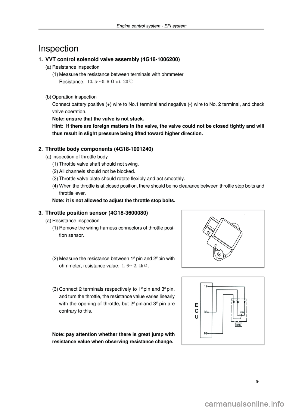
(1) Remove the wiring harness connectors of throttle posi-
tion sensor.
(2) Measure the resistance between 1# pin and 2# pin with
ohmmeter, resistance value: .
(3) Connect 2 terminals respectively to 1# pin and 3# pin,
and turn the throttle, the resistance value varies linearly
with the opening of throttle, but 2# pin and 3# pin are
contrary to this.
Note:pay attention whether there is great jump with
resistance value when observing resistance change. 9
Page 23 of 419

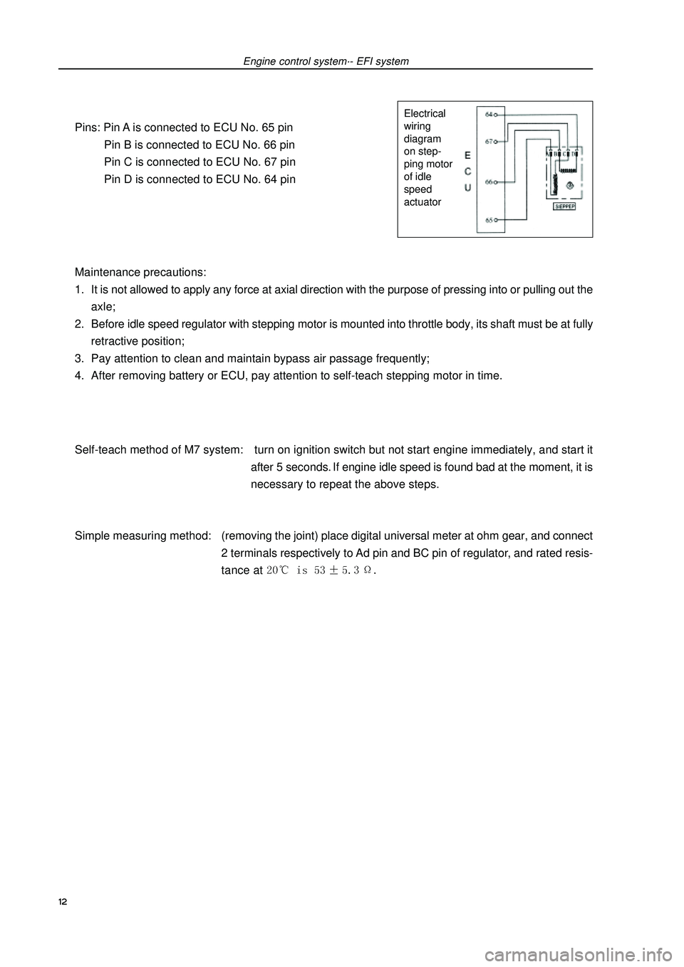
Pins: Pin A is connected to ECU No. 65 pin
Pin B is connected to ECU No. 66 pin
Pin C is connected to ECU No. 67 pin
Pin D is connected to ECU No. 64 pin
Maintenance precautions:
1. It is not allowed to apply any force at axial direction with the purpose of pressing into or pulling out the
axle;
2. Before idle speed regulator with stepping motor is mounted into throttle body, its shaft must be at fully
retractive position;
3. Pay attention to clean and maintain bypass air passage frequently;
4. After removing battery or ECU, pay attention to self-teach stepping motor in time.
Self-teach method of M7 system: turn on ignition switch but not start engine immediately, and start it
after 5 seconds. If engine idle speed is found bad at the moment, it is
necessary to repeat the above steps.
Simple measuring method:(removing the joint) place digital universal meter at ohm gear, and connect
2 terminals respectively to Ad pin and BC pin of regulator, and rated resis-
tance at Engine control system·- EFI systemElectrical
wiring
diagram
on step-
ping motor
of idle
speed
actuator12
Page 124 of 419

Drive shaft--Front drive shaftFront drive shaftOverhaulHint: overhaul procedure for right side is same as the left
side.1. Check the drive shaft (referring to page 111).
2. Discharge the oil in gearbox.(a) Disassemble oil plug and gasket to discharge the oil in
gearbox.
(b) Change with a new gasket and assemble oil discharging
plug.
Torque: 45
± ±± ±
± 5 N·m3. Disassemble front wheels.
4. Disassemble fixing nut of drive shaft [64000083](a) Use special tool and hammer to unclench the concave part
of fixing nut.
(b) Disassemble the fixing nut.5. Disassemble speed sensor assembly of left front
wheels (equipping with ABS) [67000020](a) Disassemble the bolt, and disassemble sensor wiring har-
ness and brake hose from the absorber.
(b) Disassemble the bolt, and disassemble speed sensor from
steering knuckle.special
tool113
Page 133 of 419
 Assemble lower ball joint on lower suspension arm with the
bolts and screw caps.
Torque: 142 ± 10 N
⋅ ⋅⋅ GEELY FC 2008 Workshop Manual Drive shaft--Front drive shaft35. Assemble left lower control arm assembly [64000091](a) Assemble lower ball joint on lower suspension arm with the
bolts and screw caps.
Torque: 142 ± 10 N
⋅ ⋅⋅](/img/58/57161/w960_57161-132.png)
Drive shaft--Front drive shaft35. Assemble left lower control arm assembly [64000091](a) Assemble lower ball joint on lower suspension arm with the
bolts and screw caps.
Torque: 142 ± 10 N
⋅ ⋅⋅ ⋅
⋅m36. Assemble left transversal lever assembly.(a) Assemble transversal lever terminal to steering knuckle with
screw cap.
Torque: 49 ± 5 N
⋅ ⋅⋅ ⋅
⋅m
(b) Assemble new cotter pin.
Note: if hole position of cotter pin could not make a
line, lock the screw cap for 60.37. Assemble speed sensor assembly of left front
wheels (equipping with ABS) [67000020](a) Assemble speed sensor absorber with bolts.
Torque: 49 ± 5 N
⋅ ⋅⋅ ⋅
⋅m
(b) Assemble speed sensor on the steering knuckle with bolts.
Torque: 8 N
⋅ ⋅⋅ ⋅
⋅m
Note:�zDo not damage speed sensor.�zPrevent it from contacting with sundries.�zWhen assembling the sensor, the wiring harness
of sensor could not bend.38. Assemble fixing nuts of drive shaft [68000083](a) Assemble fixing nuts.
Torque: 216 ± 15 N
⋅ ⋅⋅ ⋅
⋅m
(b) Use chisel and hammer to knock the fixing nuts concave
and fix them.39. Assemble front wheels.Torque: 103 ± 10 N
⋅ ⋅⋅ ⋅
⋅m40. Add the oil in gearbox.
41. Check and adjust the oil in gearbox.
42. Check and adjust wheel alignment (referring to page
87)
43. Check the ABS speed sensor (equipping with ABS).
44. Test on road.
122
Page 134 of 419

Driveshaft--Left front shaft hub assemblyLeft front shaft hub assemblyChangeHint: changing procedure for right side is same as the left
side.1. Disassemble front wheels
2. Disassemble fixing nuts of left front drive shaft
[64000083](a) Use special tool and hammer to unclench concave part of
fixing nuts.
(b) Disassemble fixing nuts.3. Disassemble speed sensor assembly of left front
wheel [67000020](a) Disassemble the bolts, then disassemble the wiring har-
ness of sensor and brake hose.
(b) Disassemble the bolts, then disassemble speed sensor
from steering knuckle.4. Disassemble left front brake caliper assemblyDisassemble two bolts to disassemble brake caliper bracket.Special
tool123
Page 138 of 419

Drive shaft--Left front shaft hub assemblyUse centimeter to check the axial clearance of shaft hub center.
Maximal value: 0.05 mm
If axial clearance exceeds the maximal value, it is necessary
to change the bearing.28. Check the terminal face run-out of shaft hub.Use centimeter to check the terminal run-out of exterior sur-
face of shaft hub.
Maximal value: 0.05 mm
If terminal run-out exceeds the maximal value, change the shaft
hub.29. Assemble left front brake assembly [64000134]
30. Assemble left front brake branch pump assemblyUse two bolts to assemble brake branch pump assembly on
steering knuckle.
Torque: 106
± ±± ±
± 10 N
⋅ ⋅⋅ ⋅
⋅m31. Assemble speed sensor assembly of left front wheel
[67000020](a) Assemble wiring harness of speed sensor and brake hose
on the absorber with bolts.
Torque: 29 N
⋅ ⋅⋅ ⋅
⋅m
(b) Use the bolts to assemble speed sensor to steering knuckle.
Torque: 8.0 N
⋅ ⋅⋅ ⋅
⋅m
Note: Do not damage the speed sensor.�zPrevent it from contacting with sundries.�zWhen assembling the sensor, wiring harness of sen-
sor could not bend.32. Assemble fixing nut of left front drive shaft
[64000083](a) Assemble new fixing nuts,
Torque: 216
± ±± ±
± 15 N
⋅ ⋅⋅ ⋅
⋅m
(b) Use chisel and hammer to make fixing nut concave and fix
them.33. Assemble front wheels.Torque: 103
± ±± ±
± 10 N
⋅ ⋅⋅ ⋅
⋅m34. Check and adjust wheel alignment (referring to page
87).
35. Check the ABS speed sensor signal.
127
Page 140 of 419

Drive shaft--Left rear shaft hub and bearing assemblyLeft rear shaft hub and bearing assemblyChangeHint: changing procedure for right side is same as left side.129 6. Disassemble rear wheel speed sensor assembly (equipping with ABS) [67000023]
(referring to page 52)
7. Assemble rear wheel speed sensor assembly (equipping with ABS) [67000023] (referring
to page 52) 1. Disassemble rear wheels.
2. Disassemble rear brake caliper assembleDisassemble two bolts and take down brake caliper.3. Disassemble the wiring harness of rear wheel speed
sensor (equipping with ABS).Disassemble the joint of rear wheel speed sensor.4. Disassemble left rear brake assembly [64000137]
5. Disassemble left rear shaft hub and bearing
assembly.Disassemble four bolts, then take down lower shaft hub and
bearing assembly.8. Assemble left rear shaft hub and bearing assemblyUse four bolts to assemble left rear shaft hub and bearing
assembly9. Assemble wiring harness of rear wheel speed sen-
sor (equipping with ABS).Connect the joint of rear wheel speed sensor.
Page 162 of 419

Brake--Speed sensor of front wheelSpeed sensor of front wheelChangeHint: the process for changing right side is same as the
left side.1. Disassemble front wheels.
2. Disassemble gasket of left front wing.
3. Disassemble speed sensor of left front wheel.(a) Disassemble resinous clamp and speed sensor wiring har-
ness from fixing clamp of automobile body.
(b) Disassemble the sensor joint.
(c) Disassemble two bolts of fixing clamp of sensor wiring har-
ness from automobile body and absorber.
(d) Disassemble bolt and left front sensor.
Note: do not attach any sundries on top of sensor.4. Assemble speed sensor of left front wheel.(a) Use bolt to assemble left front sensor.
Torque: 8.0 N
⋅ ⋅⋅ ⋅
⋅m
Note: do not attach any sundries on top of sensor.
(b) Use two bolts to assemble fixing clamp of sensor wiring
harness on automobile body and absorber.
Bolt A: 9.0 N
⋅ ⋅⋅ ⋅
⋅m
Bolt B: 29 N
⋅ ⋅⋅ ⋅
⋅m
(c) Connect the joint of speed sensor.
(d) Connect resinous clamp and speed sensor wiring harness
on automobile body and fixing clamp.5. Assemble gasket of left front wheel wing.
6. Assemble front wheels.Torque: 103
± ±± ±
± 10 N
⋅ ⋅⋅ ⋅
⋅m7. Check the signal of ABS speed sensor.151
Page 163 of 419

Brake--Speed sensor of rear wheelsSpeed sensor of rear wheelsChangeHint: the process for changing right side is same as the
left side.1. Disassemble rear wheels.
2. Disassemble wiring harness of speed sensor of rear
wheel.Disassemble the joint of speed sensor of rear wheel.3. Disassemble left rear disk brake branch pump
assembly.
4. Disassemble rear brake disk.
5. Disassemble left rear shaft hub and bearing assem-
bly (referring to page 129).
6. Disassemble speed sensor of rear wheel.(a) Fix rear shaft hub on pliers with soft gasket.
Note: when changing shaft hub assembly, it is neces-
sary to shake intensively to make it break off.
(b) Use punch pin and hammer to knock out two pins.
(c) Use special tool and two bolts (M12*1.5) to disassemble
speed sensor of rear wheel from rear shaft hub.
Note:�zIf sensor stator is damaged, change the shaft hub
assembly.�zDo not scratch the surface of shaft hub and speed
sensor.7. Assemble speed sensor of rear wheels.(a) Wash contacting surface of rear shaft hub and new speed
sensor of rear wheels.
(b) When sensor is assembled in shaft hub, it is necessary
to assemble sensor joint facing lower position of
automobile.Special
tool
Special tool Bolt
Bolt152
Page 164 of 419

Brake--Speed sensor of rear wheels153(c) Use special tool and press to assemble speed sensor of
rear wheels to rear shaft hub.
Note:�zDo not use hammer knock directly in speed sensor
of rear wheels.�zInsure no sundries are attached on the supervising
part of speed sensor of rear wheels�zPress speed sensor of rear wheels straightly and
slowly.8. Assemble left rear shaft hub and bearing assembly
(referring to page 129).
9. Assemble brake disk.
10. Assemble left rear brake branch pump.
11. Assemble wiring harness of speed sensor of rear
wheels.
12. Assemble rear wheels.Torque: 103
± ±± ±
± 10 N
⋅ ⋅⋅ ⋅
⋅m13. Check and adjust wheel alignment.
14. Check the signal of ABS speed sensor.Special
tool