manual transmission GEELY MK 2008 Workshop Manual
[x] Cancel search | Manufacturer: GEELY, Model Year: 2008, Model line: MK, Model: GEELY MK 2008Pages: 416, PDF Size: 25.19 MB
Page 3 of 416
Geely “MK” series sedans (JL7132U,JL7132HU,JL7152U,JL7152HU,JL7162U) are brand
new superior models developed by Geely Group who has fully proprietary intellectual property
rights. As a result of the three years of involvements and efforts of the experts from Geely Automo-
bile Research Institute, these sedans reach international leading level in model design, power,
sense of comfort, safety and manufacturing technology while featured in beautiful appearance,
economy, environment protection and safety. The meaning of MK implied that Geely Automobile
has a great development from caterpillar to butterfly. With respect to the power, Geely “MK” series
sedans are equipped with 1.3L, 1.5L, and 1.6L EFI engines developed and manufactured by Geely
itself, and has reached “Chinese III” (Euro III) emission standard.
This manual contains a detailed description of the structures and principles, servicing and adjustment,
removal, assembling technology and matching clearance of the parts of the Geely “MK” sedans
with torque information of the bolts and nuts as well as schematic diagram for special tool operation.
This manual also introduces the transmission control system of the automatic transmission models,
vehicle electric circuits and elaborates ABS system, SRS, BOSCH M7.9.7 electronic control fuel
injection and ignition system, rear parking radar, sound, air conditioning and onboard hands-free
phone system. You can refer to this manual for the information about the regular maintenance,
servicing, adjustment, troubleshooting, removal and installation procedure, specific operations of
the “MK” sedans.
This manual covers the matching relation among the engine assembly, transmission assembly and
the vehicle, but does not have the further description of the structures and principles of the engine
and transmission assemblies and their servicing process. You can refer to the service manuals
solely prepared for engine assembly and transmission assembly for these information.
All information in this manual is based on the latest products released at the time of publication of
this manual. However, the specifications and procedures may need to be modified, and the subse-
quent change will be revealed in later versions.
This manual is prepared by Geely Automobile Research Institute under the assistance of technical
staff from Zhejiang Geely Automobile Co., Ltd and Geely International Corporation. Readers
discovering during the use of this manual the errors and careless omissions due to limited skills of
the preparers and tight schedule are encouraged and pled to contact Geely International in time for
our timely correction of the mistakes.ForewordGeely International Corporation
Nov . 2007
Page 5 of 416
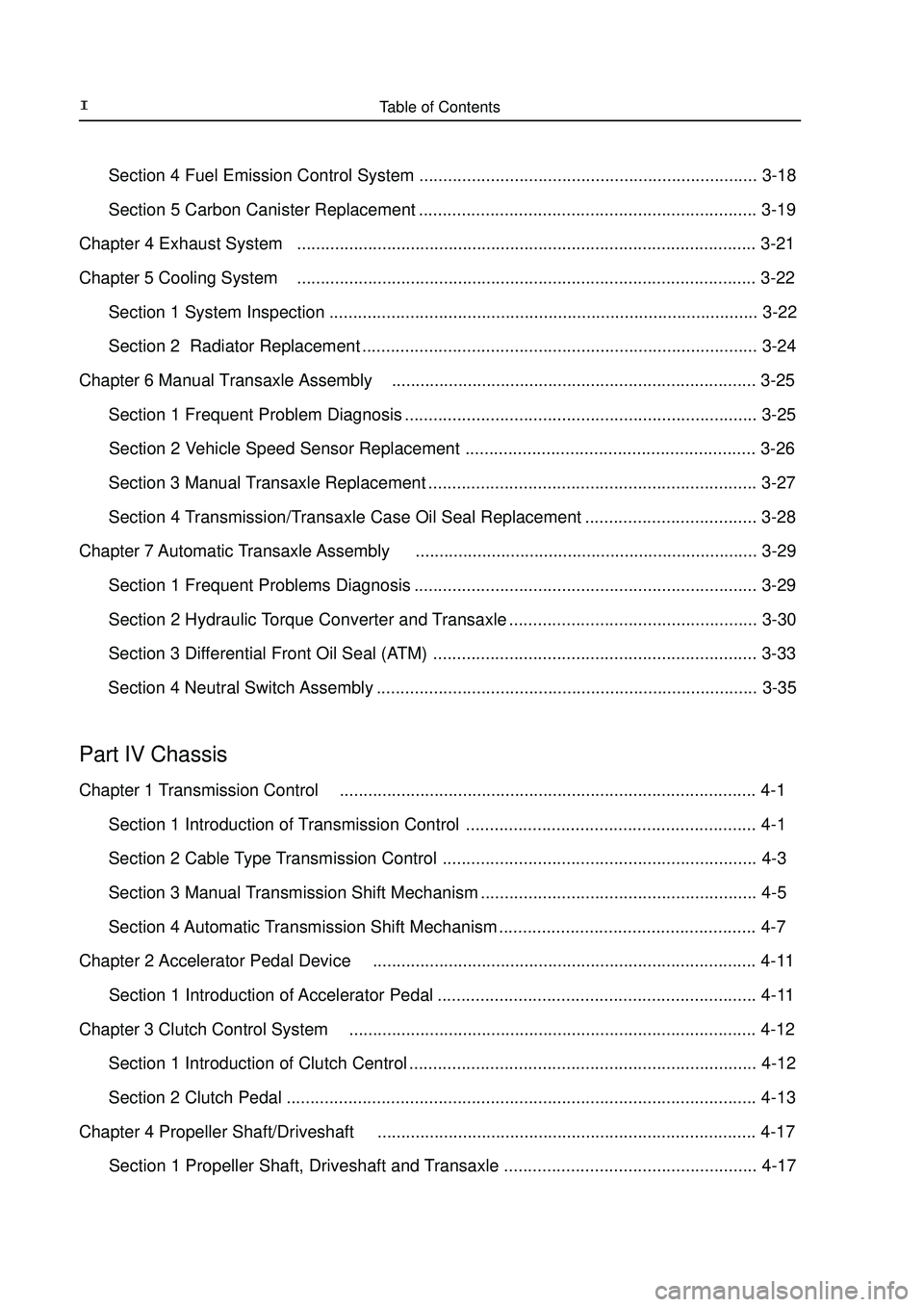
Table of Contents II Section 4 Fuel Emission Control System ....................................................................... 3-18
Section 5 Carbon Canister Replacement ....................................................................... 3-19
Chapter 4 Exhaust System................................................................................................. 3-21
Chapter 5 Cooling System................................................................................................. 3-22
Section 1 System Inspection .......................................................................................... 3-22
Section 2 Radiator Replacement ................................................................................... 3-24
Chapter 6 Manual Transaxle Assembly............................................................................. 3-25
Section 1 Frequent Problem Diagnosis .......................................................................... 3-25
Section 2 Vehicle Speed Sensor Replacement ............................................................. 3-26
Section 3 Manual Transaxle Replacement ..................................................................... 3-27
Section 4 Transmission/Transaxle Case Oil Seal Replacement .................................... 3-28
Chapter 7 Automatic Transaxle Assembly........................................................................ 3-29
Section 1 Frequent Problems Diagnosis ........................................................................ 3-29
Section 2 Hydraulic Torque Converter and Transaxle .................................................... 3-30
Section 3 Differential Front Oil Seal (ATM) .................................................................... 3-33
Section 4 Neutral Switch Assembly ................................................................................ 3-35Part IV ChassisChapter 1 Transmission Control........................................................................................ 4-1
Section 1 Introduction of Transmission Control ............................................................. 4-1
Section 2 Cable Type Transmission Control .................................................................. 4-3
Section 3 Manual Transmission Shift Mechanism .......................................................... 4-5
Section 4 Automatic Transmission Shift Mechanism ...................................................... 4-7
Chapter 2 Accelerator Pedal Device................................................................................. 4-11
Section 1 Introduction of Accelerator Pedal ................................................................... 4-11
Chapter 3 Clutch Control System...................................................................................... 4-12
Section 1 Introduction of Clutch Centrol ......................................................................... 4-12
Section 2 Clutch Pedal ...................................................................................................4-13
Chapter 4 Propeller Shaft/Driveshaft................................................................................ 4-17
Section 1 Propeller Shaft, Driveshaft and Transaxle ..................................................... 4-17
Page 11 of 416

General Information - How to Use This Manual1-2II. Vehicle Identification1. Vehicle Identification Number
(VIN):
Vehicle Identification Number
(VIN) is the legal identification of the
vehicle which is printed on the middle
of the engine compartment cowl (as
shown in the illustration).VIN code position3. Ex-work Nameplate: on the middle of the engine
compartment cowl
4. VIN Code: on the left lower corner of the front windshield.
5. Engine Number:
marked on the engine block as shown in the illustration6. Transmission Mark:
printed on the left side of the transmission 2. VIN CodeMark positionMark position
Page 19 of 416

General Information - Repair Instruction1-103.Precautions for Use of Jack and Safety Stand
(1)always use the wheel stoppers when performing servicing on
level ground.
(2)use safety stand and rubber support as shown in the illustration.
(3)use the jack and safety stand to support specified location.
(4)When jacking up the front wheels of the vehicle, release the
park brake and place stoppers only behind the rear wheels. When
jacking up the rear wheels, place stoppers only before the front wheels.
(5)During the job, make sure to use safety stand instead of jack
only to support the vehicle.
(6)When only jacking up the front wheels or rear wheels, place
stoppers before or after the wheels touching the ground.
(7)when lowering the vehicle with its front wheels lifted, release
the park brake, and place the stopper only before the rear wheels.
When lowering the vehicle with its rear wheels lifted, place the stop-
per only after the front wheels. the opening of the removed inlet system parts and the engine with a
clean shop lag or gum tape.
(3)When installing the inlet system parts, check that there is no
mixing of a metal scrap.
5. Handling of Hose Clamp
(1)Before removing the hose, check the clamp position to re-tighten
it for sure.
(2)Replace a deformed or dented clamp with a new one.
(3)In case of reusing the hose, install the clamp on the hose where
it has a clamp track.
(4)For a steel band circlip, make it adjust by adding force to the
arrow mark direction after the installation.II. Vehicle Lift and Support Location1. Vehicle Conditions To Be Under Attention During Lift
(1)Generally speaking, when being lifted, the vehicle should be empty, do not lift the heavily loaded vehicles.
(2)When removing heavy parts such as engine and transmission, the center of gravity of the vehicle will move.
Place balance weight to prevent the vehicle from rolling or use special jack to support the vehicle.
2. Precautions for Use of Four-tappet Lift
(1)follow the safe operation instruction described in this manual.
(2)do not damage the tire or rim.
(3)use wheel stopper to retain the vehicle.Rubber SuportSteel Band Circlip
Clamp Trace
Page 27 of 416
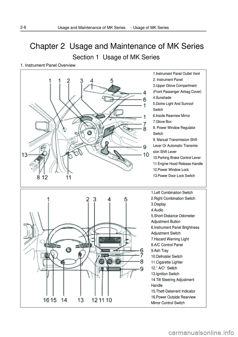
Chapter 2 Usage and Maintenance of MK SeriesSection 1 Usage of MK Series1. Instrument Panel Overview1.Instrument Panel Outlet Vent
2. Instrument Panel
3.Upper Glove Compartment
(Front Passenger Airbag Cover)
4.Sunshade
5.Dome Light And Sunroof
Switch
6.Inside Rearview Mirror
7.Glove Box
8. Power Window Regulator
Switch
9. Manual Transmission Shift
Lever Or Automatic Transmis-
sion Shift Lever
10.Parking Brake Control Lever
11.Engine Hood Release Handle
12.Power Window Lock
13.Power Door Lock Switch1.Left Combination Switch
2.Right Combination Switch
3.Display
4.Audio
5.Short-Distance Odometer
Adjustment Button
6.Instrument Panel Brightness
Adjustment Switch
7.Hazard Warning Light
8.A/C Control Panel
9.Ash Tray
10.Defroster Switch
11.Cigarette Lighter
12.”A/C“ Switch
13.Ignition Switch
14.Tilt Steering Adjustment
Handle
15.Theft-Deterrent Indicator
16.Power Outside Rearview
Mirror Control SwitchUsage and Maintenance of MK Series - Usage of MK Series2-6
Page 36 of 416
2-15
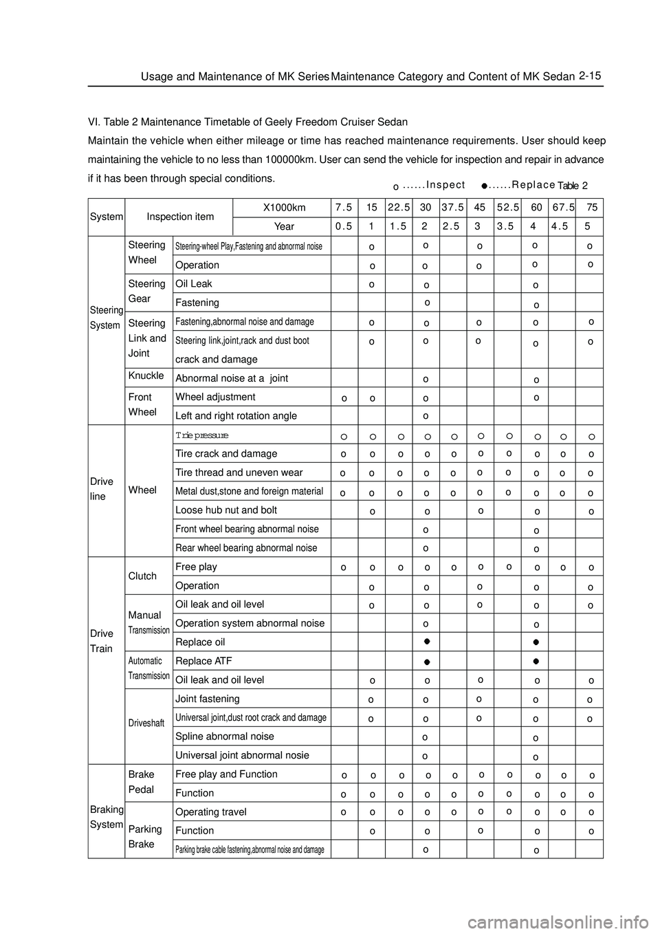
VI. Table 2 Maintenance Timetable of Geely Freedom Cruiser SedanMaintain the vehicle when either mileage or time has reached maintenance requirements. User should keep
maintaining the vehicle to no less than 100000km. User can send the vehicle for inspection and repair in advance
if it has been through special conditions.SystemInspection itemX1000km
Year7.5 15 22.5 30 37.5 45 52.5 60 67.5 75
0.5 1 1.5 2 2.5 3 3.5 4 4.5 5Steering
SystemSteering-wheel Play,Fastening and abnormal noiseOperation
Oil Leak
FasteningFastening,abnormal noise and damage
Steering link,joint,rack and dust bootcrack and damage
Abnormal noise at a joint
Wheel adjustment
Left and right rotation angle
Trie pressure
Tire crack and damage
Tire thread and uneven wearMetal dust,stone and foreign materialLoose hub nut and boltFront wheel bearing abnormal noise
Rear wheel bearing abnormal noiseFree play
Operation
Oil leak and oil level
Operation system abnormal noise
Replace oil
Replace ATF
Oil leak and oil level
Joint fasteningUniversal joint,dust root crack and damageSpline abnormal noise
Universal joint abnormal nosie
Free play and Function
Function
Operating travel
FunctionParking brake cable fastening,abnormal noise and damageo......Inspect ......ReplaceTable 2 Drive
line
Drive
Train
Braking
SystemSteering
Wheel
Steering
Gear
Steering
Link and
Joint
Knuckle
Front
Wheel
Wheel
Clutch
ManualTransmissionAutomaticTransmissionDriveshaftBrake
Pedal
Parking
BrakeUsage and Maintenance of MK Series - Maintenance Category and Content of MK Sedano
o
oo
o o oo o
o o
oo
o o
oo
ooo
o
o oo
o ooo
o o o
o
oo o o o
o o o o
o
oo o o o
o o o o
o
oo o o o
o o o o
o
oo o o o
o o o o
o
oo o o o
o o o o
o
oo o o o
o o o o
o
oo o o o
o o o o
o
oo o o o
o o o o
oo o o
o
o
o o o
o
o
o o o
o
o
o o o
o
o
o o o
o
o
o o o
o
oo o
o o
o o
o o
o o
o oo o o
o
o
Page 38 of 416
2-17
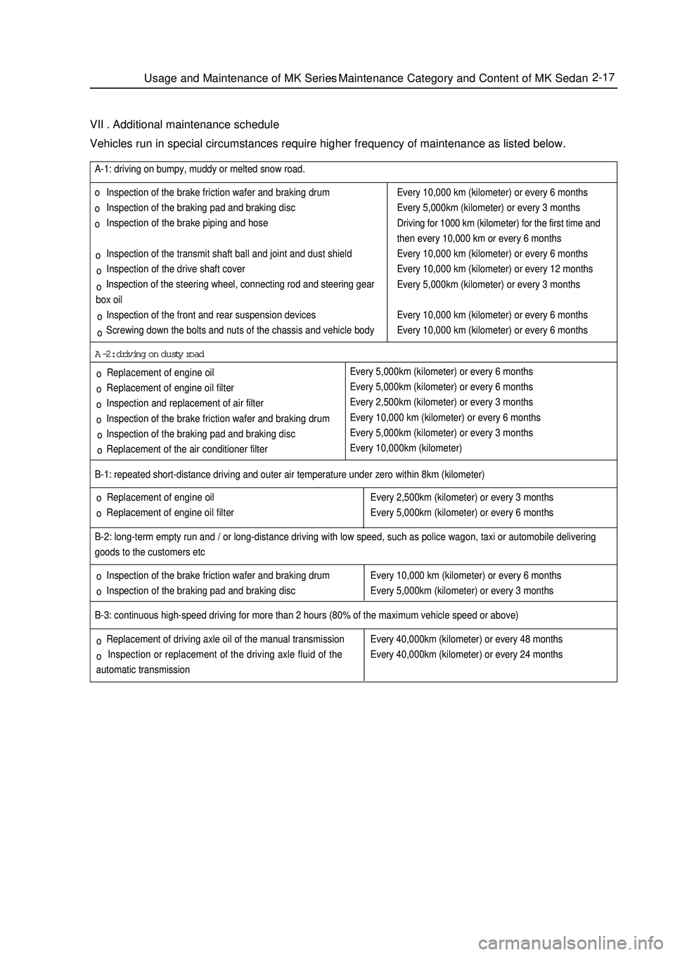
VII . Additional maintenance scheduleVehicles run in special circumstances require higher frequency of maintenance as listed below. Replacement of engine oil
Replacement of engine oil filter B-1: repeated short-distance driving and outer air temperature under zero within 8km (kilometer)
Inspection of the brake friction wafer and braking drum
Inspection of the braking pad and braking disc B-2: long-term empty run and / or long-distance driving with low speed, such as police wagon, taxi or automobile delivering
goods to the customers etcEvery 2,500km (kilometer) or every 3 months
Every 5,000km (kilometer) or every 6 months
Every 10,000 km (kilometer) or every 6 months
Every 5,000km (kilometer) or every 3 monthsB-3: continuous high-speed driving for more than 2 hours (80% of the maximum vehicle speed or above)
Replacement of driving axle oil of the manual transmission
Inspection or replacement of the driving axle fluid of the
automatic transmissionEvery 40,000km (kilometer) or every 48 months
Every 40,000km (kilometer) or every 24 months Inspection of the brake friction wafer and braking drum
Inspection of the braking pad and braking disc
Inspection of the brake piping and hose
Inspection of the transmit shaft ball and joint and dust shield
Inspection of the drive shaft cover
Inspection of the steering wheel, connecting rod and steering gear
box oil
Inspection of the front and rear suspension devices
Screwing down the bolts and nuts of the chassis and vehicle body A-1: driving on bumpy, muddy or melted snow road.
Replacement of engine oil
Replacement of engine oil filter
Inspection and replacement of air filter
Inspection of the brake friction wafer and braking drum
Inspection of the braking pad and braking disc
Replacement of the air conditioner filterA-2: driving on dusty roadEvery 10,000 km (kilometer) or every 6 months
Every 5,000km (kilometer) or every 3 months
Driving for 1000 km (kilometer) for the first time and
then every 10,000 km or every 6 months
Every 10,000 km (kilometer) or every 6 months
Every 10,000 km (kilometer) or every 12 months
Every 5,000km (kilometer) or every 3 months
Every 10,000 km (kilometer) or every 6 months
Every 10,000 km (kilometer) or every 6 months
Every 5,000km (kilometer) or every 6 months
Every 5,000km (kilometer) or every 6 months
Every 2,500km (kilometer) or every 3 months
Every 10,000 km (kilometer) or every 6 months
Every 5,000km (kilometer) or every 3 months
Every 10,000km (kilometer)Usage and Maintenance of MK Series - Maintenance Category and Content of MK Sedanoo o
o o o o
o o
o
o o
o o
o o
o ooo
Page 44 of 416
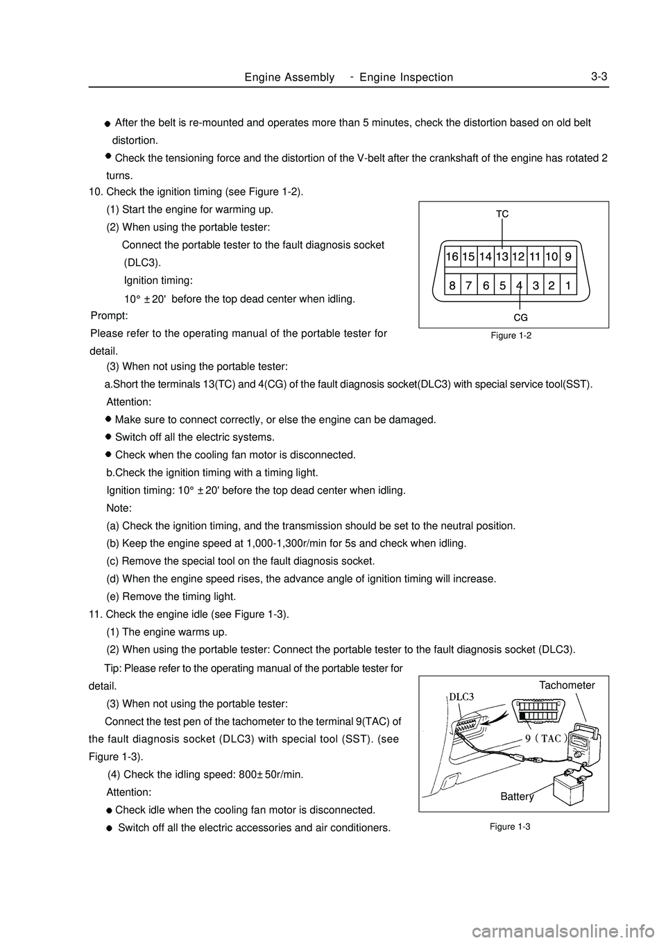
Figure 1-2
Figure 1-3Engine AssemblyEngine Inspection3-3 After the belt is re-mounted and operates more than 5 minutes, check the distortion based on old belt
distortion.
Check the tensioning force and the distortion of the V-belt after the crankshaft of the engine has rotated 2
turns.
10. Check the ignition timing (see Figure 1-2).
(1) Start the engine for warming up.
(2) When using the portable tester:
Connect the portable tester to the fault diagnosis socket
(DLC3).
Ignition timing:
before the top dead center when idling.
Prompt:
Please refer to the operating manual of the portable tester for
detail.
(3) When not using the portable tester:
a.Short the terminals 13(TC) and 4(CG) of the fault diagnosis socket(DLC3) with special service tool(SST).
Attention:
Make sure to connect correctly, or else the engine can be damaged.
Switch off all the electric systems.
Check when the cooling fan motor is disconnected.
b.Check the ignition timing with a timing light.
Ignition timing: 10°±20' before the top dead center when idling.
Note:
(a) Check the ignition timing, and the transmission should be set to the neutral position.
(b) Keep the engine speed at 1,000-1,300r/min for 5s and check when idling.
(c) Remove the special tool on the fault diagnosis socket.
(d) When the engine speed rises, the advance angle of ignition timing will increase.
(e) Remove the timing light.
11. Check the engine idle (see Figure 1-3).
(1) The engine warms up.
(2) When using the portable tester: Connect the portable tester to the fault diagnosis socket (DLC3).
Tip: Please refer to the operating manual of the portable tester for
detail.
(3) When not using the portable tester:
Connect the test pen of the tachometer to the terminal 9(TAC) of
the fault diagnosis socket (DLC3) with special tool (SST). (see
Figure 1-3).
(4) Check the idling speed: 800±50r/min.
Attention:
Check idle when the cooling fan motor is disconnected.
Switch off all the electric accessories and air conditioners.Tachometer
Battery10°±20' -
Page 66 of 416
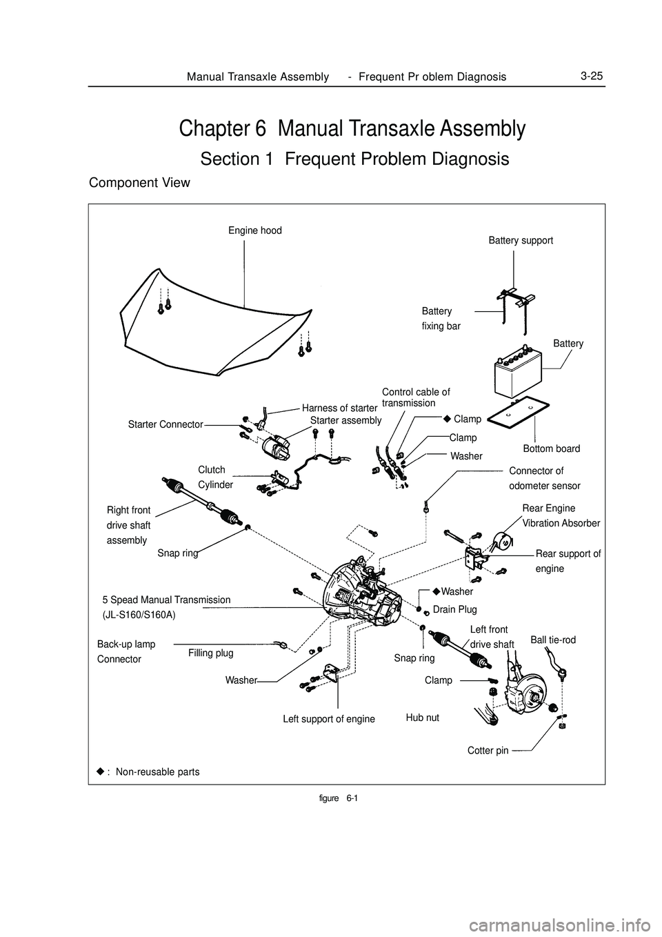
Chapter 6 Manual Transaxle AssemblySection 1 Frequent Problem DiagnosisComponent Viewfigure6-1Manual Transaxle Assembly Frequent Pr oblem Diagnosis3-25Battery support
Battery
fixing bar
Bottom board
Rear Engine
Vibration Absorber Starter assembly Engine hood
Control cable of
transmissionBattery
Harness of starter
Clamp
Clamp
Washer
Connector of
odometer sensor Clutch
Cylinder Starter Connector
Rear support of
engine
5 Spead Manual Transmission
(JL-S160/S160A)
Left front
drive shaftBall tie-rod
Cotter pin Hub nut Snap ring
Clamp
Left support of engineWasher
Washer Back-up lamp
ConnectorFilling plugDrain Plug Right front
drive shaft
assembly
Snap ring: Non-reusable parts -
Page 67 of 416

Table 6-1 Frequent problem diagnosisPossible causes
Transmission or the engine is suspended loosely or damaged;
Axial gap is improper;
Gear or bearing is worn or damaged;
Unsatisfactory transmission oil is used or oil level is low;
Engine idle is incorrect.
The oil seal or the O-ring is damaged.
The control cable is unqualified;
Synchronizer is poorly contacted with gear or worn;
Elasticity of the synchronous spring is insufficient;
Unqualified transmission oil is used.
Fork of the shift gear is worn or lifting spring is broken;
Gap between the synchronizer bush and the sleeve spline is too large;
Gear or bearing is worn or damaged. Sympton
Vibration and noise
Oil leakage of the transmission
Hard to shift
Trip stopManual Transaxle Assembly Vehicle Speed Sensor Replacement3-261. Disengage the vehicle speed sensor (see Figure 6-2).
2. Remove the bolt and the vehicle speed sensor.
3. Mount the vehicle speed sensor (see Figure 6-3).
4. Connect the vehicle speed sensor.Section 2 Vehicle Speed Sensor ReplacementFigure 6-2
Figure 6-3 -