manual transmission GEELY MK 2008 User Guide
[x] Cancel search | Manufacturer: GEELY, Model Year: 2008, Model line: MK, Model: GEELY MK 2008Pages: 416, PDF Size: 25.19 MB
Page 68 of 416

Figure 6-5Manual Transaxle Assembly Manual Transaxle Replacement3-27Section 3 Manual Transaxle ReplacementReplace1. Open the engine cover.
2. Remove the battery.
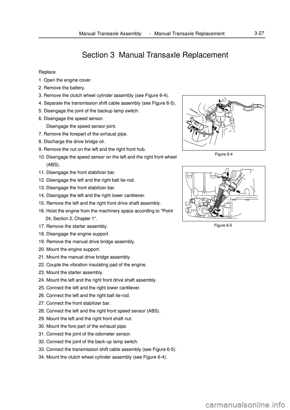
3. Remove the clutch wheel cylinder assembly (see Figure 6-4).
4. Separate the transmission shift cable assembly (see Figure 6-5).
5. Disengage the joint of the backup lamp switch.
6. Disengage the speed sensor.
Disengage the speed sensor joint.
7. Remove the forepart of the exhaust pipe.
8. Discharge the drive bridge oil.
9. Remove the nut on the left and the right front hub.
10. Disengage the speed sensor on the left and the right front wheel
(ABS).
11. Disengage the front stabilizer bar.
12. Disengage the left and the right ball tie-rod.
13. Disengage the front stabilizer bar.
14. Disengage the left and the right lower cantilever.
15. Remove the left and the right front drive shaft assembly.
16. Hoist the engine from the machinery space according to "Point
24, Section 2, Chapter 1".
17. Remove the starter assembly.
18. Disengage the engine support.
19. Remove the manual drive bridge assembly.
20. Mount the engine support.
21. Mount the manual drive bridge assembly.
22. Couple the vibration insulating pad of the engine.
23. Mount the starter assembly.
24. Mount the left and the right front drive shaft assembly.
25. Connect the left and the right lower cantilever.
26. Connect the left and the right ball tie-rod.
27. Connect the front stabilizer bar.
28. Connect the left and the right front speed sensor (ABS).
29. Mount the left and the right front shaft nut.
30. Mount the fore part of the exhaust pipe.
31. Connect the joint of the odometer sensor.
32. Connect the joint of the back-up lamp switch.
33. Connect the transmission shift cable assembly (see Figure 6-5).
34. Mount the clutch wheel cylinder assembly (see Figure 6-4).Figure 6-4 -
Page 69 of 416

I. Replace the oil seal of transmission housing1. Remove the oil seal of the transmission housing (see Figure 6-6).
2. Mount the oil seal of the transmission housing (see Figure 6-7).
Attention:
Take care not to damage the lip surface of the oil seal.II. Replace the Oil Seal of the Drive Bridge Housing1. Remove the oil seal of the transaxle housing with special
maintenance tool (see Figure 6-8).
2. Mount the oil seal of the transaxle housing (see Figure 6-9).Section 4 Transmission/Transaxle Case Oil Seal ReplacementFigure 6-6
Figure 6-7Figure 6-8
Figure 6-9Manual Transaxle Assembly Transmission/Transaxle Case Oil Seal Replacement3-28 -
Page 72 of 416

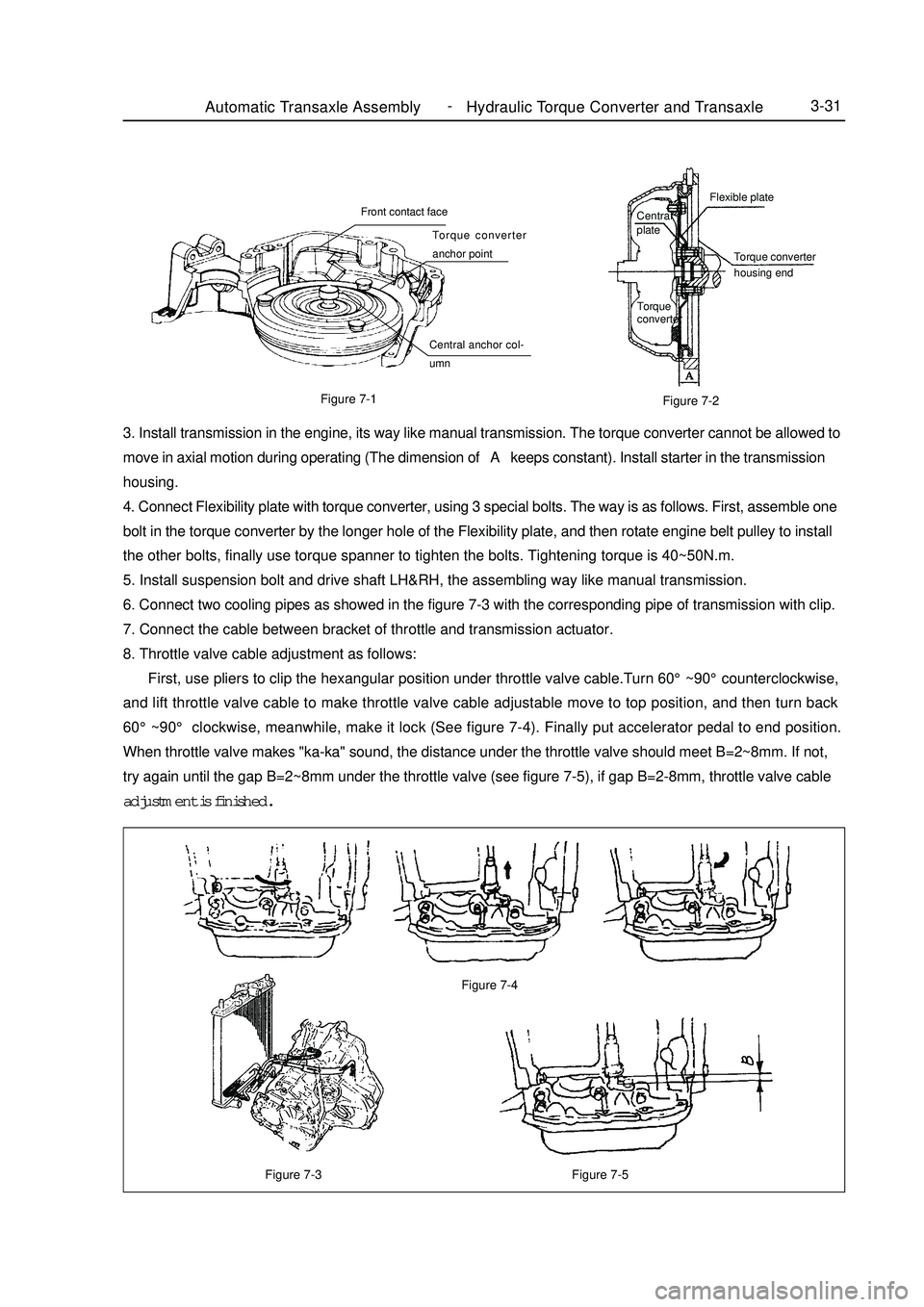
Figure 7-3Automatic Transaxle Assembly Hydraulic Torque Converter and Transaxle3-31Figure 7-5 Figure 7-4Figure 7-1
Figure 7-23. Install transmission in the engine, its way like manual transmission. The torque converter cannot be allowed to
move in axial motion during operating (The dimension of A keeps constant). Install starter in the transmission
housing.
4. Connect Flexibility plate with torque converter, using 3 special bolts. The way is as follows. First, assemble one
bolt in the torque converter by the longer hole of the Flexibility plate, and then rotate engine belt pulley to install
the other bolts, finally use torque spanner to tighten the bolts. Tightening torque is 40~50N.m.
5. Install suspension bolt and drive shaft LH&RH, the assembling way like manual transmission.
6. Connect two cooling pipes as showed in the figure 7-3 with the corresponding pipe of transmission with clip.
7. Connect the cable between bracket of throttle and transmission actuator.
8. Throttle valve cable adjustment as follows:
First, use pliers to clip the hexangular position under throttle valve cable.Turn 60°~90°counterclockwise,
and lift throttle valve cable to make throttle valve cable adjustable move to top position, and then turn back
60°~90° clockwise, meanwhile, make it lock (See figure 7-4). Finally put accelerator pedal to end position.
When throttle valve makes "ka-ka" sound, the distance under the throttle valve should meet B=2~8mm. If not,
try again until the gap B=2~8mm under the throttle valve (see figure 7-5), if gap B=2-8mm, throttle valve cable
adjustment is finished.Central
plateFlexible plate
Torque converter
housing end
Torque
converterFront contact face
Torque converter
anchor point
Central anchor col-
umn -
Page 80 of 416

Section 2 Cable Type Transmission ControlReplacement1. Remove the upper cover in dashboard panel.
2. Remove the lower cover in dashboard panel.
3. Remove the cup-holder in the middle console.
4. Loosen transmission control cover.
5. Remove the handle of the gear shift lever.
6. Remove the middle console body.
7. Remove the control cables assembly of the transmission.
(1) Remove the two cotter pins and unfix the head of the control
cables of the transmission (see the right figure).
(2) Remove the control cables assembly after loosening the shift
bracket with bolts.
(3) Remove the two cotter pins and two washers, and then unfix
the two control cables from the manual transmission.
(4) Remove the two spring clips and unfix the two control cables
from the bracket.
(5) Remove the bolt and unfix the control cables.
(6) Remove the two bolts.
(7) Pull the control cables out of the body.
(8) Remove the retainer from the control cables.Transmission ControlCable Type Transmission Control4-3 -
Page 82 of 416

Section 3 Manual Transmission Shift MechanismReplacement1. Remove the upper cover in dashboard panel.
2. Remove the lower cover in dashboard panel.
3. Remove the cup-holder in the middle console.
4. Loosen transmission control cover.
5. Remove the handle of the gear shift lever.
6. Remove the middle console body.
7. Remove the control cables assembly of the transmission.
(1) Remove the two cotter pins and unfix the head of the control
cables of the transmission
(2) Remove the spring clips and separate the control cables from
the bracket.
8. Remove the four bolts and floor gear shift lever assembly.
9. Install the floor gear shift lever assembly.
Install the floor gear shift lever assembly with four bolts.
Torque: 12N.mTransmission ControlManual Transmission Shift Mechanism4-5 -
Page 83 of 416

Transmission ControlManual Transmission Shift Mechanism4-610. Connect the control cables assembly.
(1) Connect the control cables to floor gear shift lever assembly.
Note:
Make sure the spring clips engage firmly.
(2) Connect the ends of the control cables to the floor gear shift
lever assembly, and then install the cotter pins.
Note:
When connecting the ends, the dents shall be made upwards.
The cotter pins are inserted in a direction as shown in the figure.
(3) Connect the ends of the gear shift cables to the floor gear shift
lever assembly.
11. Install the middle console body.
12. Install the parking brake cover.
13. Install the handle of the gear shift lever.
14. Install the cup-holder.
15. Install the lower cover in dashboard panel.
16. Install the upper cover in dashboard panel.Sawcat part -
Page 98 of 416

Overhaul1. Drain manual transmission oil (M/T transmission)
Torque: 39N.m
2. Drain automatic transmission oil (A/T transmission)
Torque: 25N.m
3. Remove front wheel
4. Remove engine bottom left shield (M/T transaxle)
5. Remove engine bottom right shield (M/T transaxle)
6. Remove engine bottom shield assembly (A/T transaxle)
7. Remove front wheel hub left bolt
(1) Using a hammer and a drive shaft nut chisel, unstake the
staked part of the left wheel hub nut.
(2) While applying the brake pedal, remove the left wheel hub
nut.
Notice: the staked part of the nut should be fully unstaked,
otherwise it may damage the thread of the drive shaft.
8. Remove left front vehicle speed sensor (with ABS)
(1) Remove the bolt and clip, remove vehicle speed sensor and
brake hose from left front shock absorber assembly.
(2) Remove the bolt, separate the left front vehicle speed sensor
from steering knuckle.
9. Remove front stabilizer bar
(1) Use a 10mm wrench to hold the bolt, remove the nut
(2) Remove two collars, No.1 and No.2 gaskets, remove front
stabilizer barPropeller Shaft/DriveshaftFront Driveshaft4-21 -
Page 105 of 416

Propeller Shaft/DriveshaftFront Driveshaft4-28 Hint:
Please refer to the following table for dimension (A).LH mm
528.3±5.0
527.0±5.0RH mm
859.3±5.0
860.0±5.0 M/T manual transmission
A/T automatic transmission38. Install left constant velocity drive shaft assembly
(1) M/T
Coat the spline of the tripod joint assembly with gear oil.
(2) A/T
Coat the spline of the tripod joint assembly with ATF
(Automatic Transmission Fluid).
(3) Align the spline, use a brass bar and hammer to install the left
drive shaft assembly.
Notice:
Face the retainer open end downward.
Be careful not to damage the boot and oil seal.
Hint:
You can find out whether the tripod joint shaft contact the pinion shaft by rotating the shaft assembly, listening
to the sound and feeling.
39. Install right constant velocity drive shaft assembly
Hint:
The installation of the right side is the same as that of the left side.
Notice:
Install the retainer with its open end facing downward.
Be careful not to damage the boot and oil seal.
40. Install left steering knuckle assembly
Install the left constant velocity drive shaft assembly on the left steering knuckle assembly.
Notice:
Be careful not to damage the outboard joint boot.
With ABS:
Be careful not to damage the vehicle speed sensor rotor.
41. Install left steering gear with tie rod assembly
(1) Install the steering gear with tie rod assembly on the steering knuckle assembly with nuts.
Torque: 33N.m
(2) Install the new cotter pins.
Notice:
If the pin holes are not aligned, further tighten the nut by 60°.
42. Install left lower swing arm assembly
(1) Install the left lower swing arm assembly on the steering knuckle assembly with nuts.
Torque: 98N.m -
Page 106 of 416

Propeller Shaft/DriveshaftFront Driveshaft4-29 (2) Install the new cotter pins.
Notice:
If the pin holes are not aligned, further tighten the nut by 60°.
43. Install front stabilizer bar
(1) As shown in the illustration, install the stabilizer bar with two
No.1 collars and two gaskets and nuts.
Notice:
Make sure the gaskets and collars are correctly installed.
(2) Tighten the nut with a 10mm wrench.
Torque: 18N.m
44. Install left front vehicle speed sensor (with ABS)
(1) Install the left front vehicle speed sensor and brake hose on the
front shock absorber with bolts and clps.
Torque: 29N.m
(2) Install the vehicle speed sensor on the steering knuckle with
bolts.
Torque: 8.0N.m
Notice:
Be careful not to damage the wheel speed sensor.
Keep the vehicle speed sensor clean.
When installing the sensor,do not twist the sensor wire harness.
45. Install left steering knuckle wheel hub nut
(1) Install new left steering knuckle hub nuts
Torque: 216N.m
(2) Using a chisel and hammer, stake the hub locking nut.
46. Install engine bottom left shield
47. Install engine bottom right shield
48. Install engine bottom shield assembly
49. Install front wheel
Torque: 103 N.m
50. Add oil into manual transmission
51. Check and adjust the manual transmission fluid
52. Refill automatic transmission fluid
53. Check and adjust the automatic transmission fluid
54. Check and adjust front wheel alignment
55. Check ABS vehicle speed signal (with ABS) -
Page 162 of 416

Component ViewSection 4 Brake Master Cylinder AssemblyVacuum boosterBrake System -Brake Master Cylinder Assembly4-85Brake master cylinder
sub-assembly
Vacuum tube
Fluid level indicator lamp connector Manual Transmission
#1 clutch fluidr tank pipe No ABS
specified torqueN.
m :