lock GEELY MK 2008 Owners Manual
[x] Cancel search | Manufacturer: GEELY, Model Year: 2008, Model line: MK, Model: GEELY MK 2008Pages: 416, PDF Size: 25.19 MB
Page 369 of 416

Chapter 17 Moonroof Assembly (Optional)Component ViewII. Inspection of sunroof Troubleshooting formSunshade sub-assy Sunroof motorBracket sub-assy.Sunroof frameSunroof glass bracketSunroof glass sealSunroof glassInterior & Exterior Trim and Accessory -Moonroof Assembly (Optional)6-40Possible causes
1. Power relay
2. Instrument fuse
3. Sunroof switch
4. Sunroof lock switch
5. Sunroof motor
6. Sunroof guide rail
7. Wire harness
1. Sunroof lock switch
2. Sunroof motor
3. Sunroof guide rail
4. Wire harnessSymptom
Sliding sunroof system doesn't work.
Sling sunroof system gets stuck (e.g.
foreign matter like gravel caught in motor)
Page 374 of 416
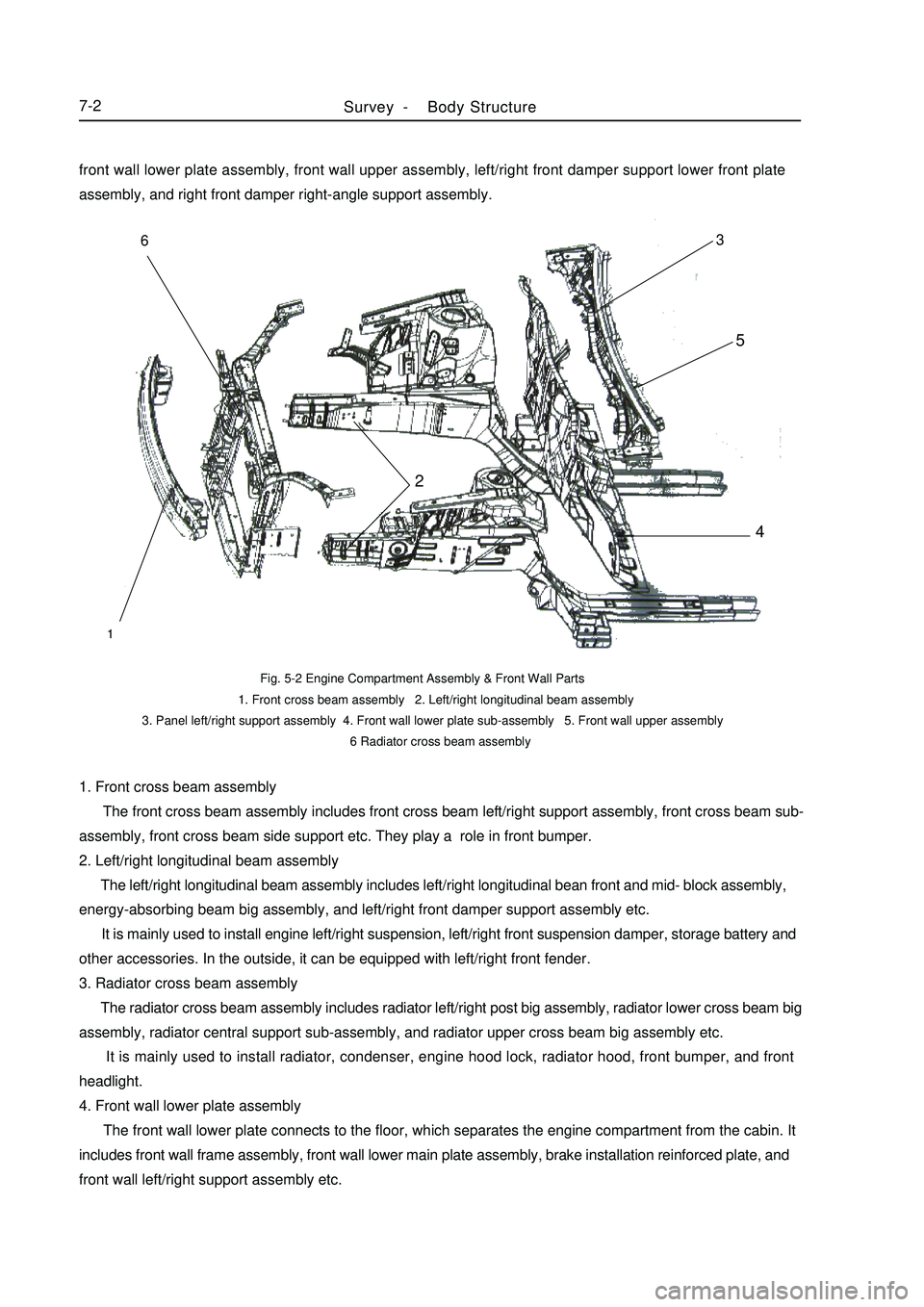
1. Front cross beam assembly
The front cross beam assembly includes front cross beam left/right support assembly, front cross beam sub-
assembly, front cross beam side support etc. They play a role in front bumper.
2. Left/right longitudinal beam assembly
The left/right longitudinal beam assembly includes left/right longitudinal bean front and mid- block assembly,
energy-absorbing beam big assembly, and left/right front damper support assembly etc.
It is mainly used to install engine left/right suspension, left/right front suspension damper, storage battery and
other accessories. In the outside, it can be equipped with left/right front fender.
3. Radiator cross beam assembly
The radiator cross beam assembly includes radiator left/right post big assembly, radiator lower cross beam big
assembly, radiator central support sub-assembly, and radiator upper cross beam big assembly etc.
It is mainly used to install radiator, condenser, engine hood lock, radiator hood, front bumper, and front
headlight.
4. Front wall lower plate assembly
The front wall lower plate connects to the floor, which separates the engine compartment from the cabin. It
includes front wall frame assembly, front wall lower main plate assembly, brake installation reinforced plate, and
front wall left/right support assembly etc.Fig. 5-2 Engine Compartment Assembly & Front Wall Parts
1. Front cross beam assembly 2. Left/right longitudinal beam assembly
3. Panel left/right support assembly 4. Front wall lower plate sub-assembly 5. Front wall upper assembly
6 Radiator cross beam assemblySurvey -Body Structure7-2123456front wall lower plate assembly, front wall upper assembly, left/right front damper support lower front plate
assembly, and right front damper right-angle support assembly.
Page 375 of 416
It is mainly used to install the pipes and accessories of the brake system and clutch system.
5. Front wall upper assembly
The front wall upper assembly includes left/right hinge base mounting plate big assembly, front wall upper
front cover big assembly, VIN number mounting plate, and front wall upper rear cover big assembly etc.
It forms a high-stiffness frame structure together with the engine compartment assembly and the front wall
lower plate assembly. It can generate strong resistant to the transverse collision and rolling deformation. It can also
separate the engine compartment form the cabin, preventing the odor entering into the cabin. Consequently, it can
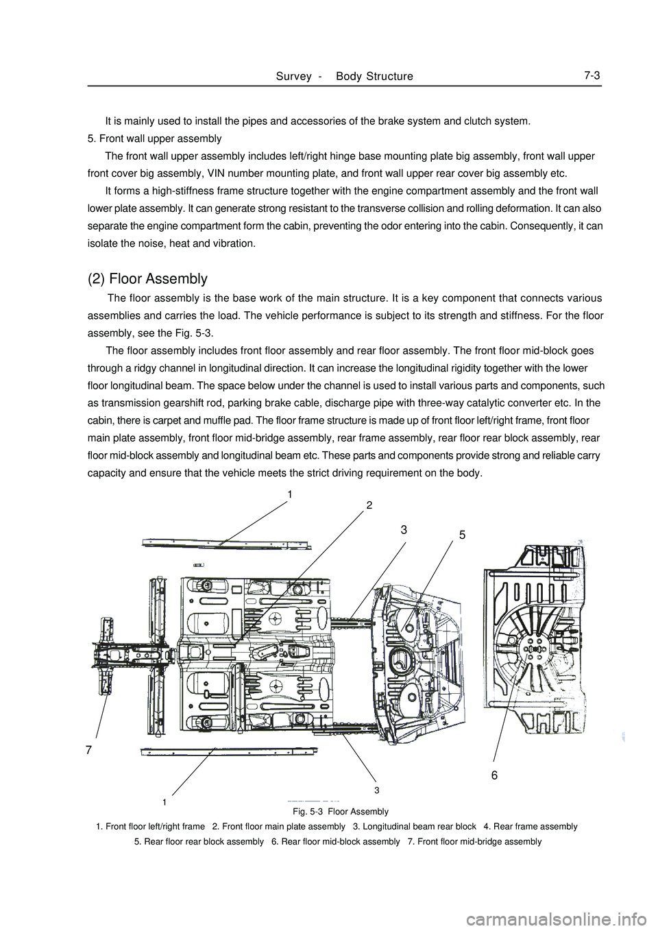
isolate the noise, heat and vibration.(2) Floor Assembly The floor assembly is the base work of the main structure. It is a key component that connects various
assemblies and carries the load. The vehicle performance is subject to its strength and stiffness. For the floor
assembly, see the Fig. 5-3.
The floor assembly includes front floor assembly and rear floor assembly. The front floor mid-block goes
through a ridgy channel in longitudinal direction. It can increase the longitudinal rigidity together with the lower
floor longitudinal beam. The space below under the channel is used to install various parts and components, such
as transmission gearshift rod, parking brake cable, discharge pipe with three-way catalytic converter etc. In the
cabin, there is carpet and muffle pad. The floor frame structure is made up of front floor left/right frame, front floor
main plate assembly, front floor mid-bridge assembly, rear frame assembly, rear floor rear block assembly, rear
floor mid-block assembly and longitudinal beam etc. These parts and components provide strong and reliable carry
capacity and ensure that the vehicle meets the strict driving requirement on the body.Fig. 5-3 Floor Assembly
1. Front floor left/right frame 2. Front floor main plate assembly 3. Longitudinal beam rear block 4. Rear frame assembly
5. Rear floor rear block assembly 6. Rear floor mid-block assembly 7. Front floor mid-bridge assemblySurvey -Body Structure7-371
2
133
5
6
Page 377 of 416

(4) Rear Wall Parts As shown in Fig.5-5, the rear wall assembly includes rear wall plate, rear wall reinforced plate, luggage
compartment door lock mounting plate and luggage compartment door cross beam etc.Fig. 5-5 Rear Wall Assembly
1. Rear wall upper cross beam
2. Luggage compartment lock
mounting plate big assembly
3. Rear wall left double-hole plate
4. Rear wall outer plate
Fig. 5-6 Roof Assembly
1. Roof outer panel 2. Roof No.1 cross beam 3. Roof No.2 cross beam 4.Roof rear cross beam 5.Roof No.3 cross beam
6. Moon roof reinforcement panel It is mainly used as a cross beam to improve the strength of the rear part of the vehicle and form a luggage
compartment door.5) Roof Assembly The roof assembly includes roof outer panel, roof No.1 and No.2 cross beam, and roof rear cross beam etc.
Inside the roof, there is top interior decoration. There is a heat pad in the center and there is bond between the cross
beam and the roof. The rain from the roof is discharged out of the rear part through the channels at both sides. These
cross beams are used to reinforce the roof's transverse stiffness. For disassembled parts, see Fig. 5-6.(6) Luggage Compartment Main Cover Assembly The luggage compartment main cover assembly includes luggage compartment main cover sub-assembly, rear
seat hook mounting plate assembly, left/right side angle plate, drip channel and reinforced upper cross beam etc.
When the luggage compartment main cover assembly is welded to the left/right side wall, it forms a luggageSurvey -Body Structure7-51 14432526143 2
Page 378 of 416
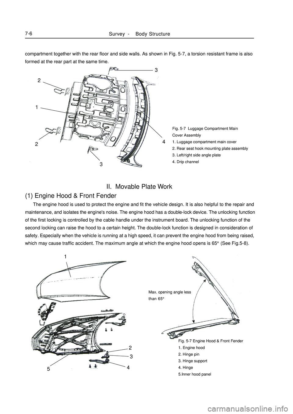
Fig. 5-7 Luggage Compartment Main
Cover Assembly
1. Luggage compartment main cover
2. Rear seat hook mounting plate assembly
3. Left/right side angle plate
4. Drip channelII. Movable Plate Work(1) Engine Hood & Front Fender The engine hood is used to protect the engine and fit the vehicle design. It is also helpful to the repair and
maintenance, and isolates the engine's noise. The engine hood has a double-lock device. The unlocking function
of the first locking is controlled by the cable handle under the instrument board. The unlocking function of the
second locking can raise the hood to a certain height. The double-lock function is designed in consideration of
safety. Especially when the vehicle is running at a high speed, it can prevent the engine hood from being raised,
which may cause traffic accident. The maximum angle at which the engine hood opens is 65°(See Fig.5-8).Fig. 5-7 Engine Hood & Front Fender
1. Engine hood
2. Hinge pin
3. Hinge support
4. Hinge
5.Inner hood panelSurvey -Body Structure7-642
3
51Max. opening angle less
than 65°compartment together with the rear floor and side walls. As shown in Fig. 5-7, a torsion resistant frame is also
formed at the rear part at the same time.3
4
213 2
Page 379 of 416

(2) Front FenderFront fender plays a role in front wheel apron and rotect person safty.And at the same tirne,if also woork as vehicle
styling parts.
For the match relationship between the front fender & engine hood and the front door, see Fig. 5-9.Fig. 5-9 Front Fender related to surrounding parts
A) With Engine Hood (4mm¡À1mm)
B) With Front Door (5mm¡À1mm)(3) Door Assembly Doors have LH/RH front door and rear door.
The door uses hinge gemel with limiting device, which is an open structure.
The door includes door outside plate, door inside plate, bumper and hinge reinforced plate etc.
The door has a complex structure, which is a movable component on the body. It helps the passengers get on/
off the vehicle and form an enclosed cabin with the main structure and the relevant parts. Meanwhile, the doors
are used frequently, so there is high requirement on their reliability and durability.
The outside/inside plate is molded by one complete steel sheet, which can improve the stiffness and precision.
In order to improve the safety when the vehicle is collided from the side, four doors are equipped with door
bumpers.
As shown in Fig. 5-10 and Fig. 5-11, the door assembly is made up of outside plate assembly and inside plate
assembly.Fig. 5-10 Front Door
1. Front door inner panel 2. Left front door inner reinforced panel 3. Front door window opper rail 4. Door lock reinforced panel
5. Left front door inner plate cross beam 6. Front door outer panel 7. Door bumper assembly
8. Front door upper hinge assembly 9. Front door lower hinge assembly 10. Hinge reinforced panel assemblySurvey -Body Structure7-7Engine hood
Front fenderFront door
Front fenderA
B12345678910
Page 380 of 416

Fig. 5-11 Rear Door
1. Rear door inner panel 2. Rear door inner lock mounting panel 3. Rear door glass rail 4. Rear inner plate cross beam
5. Rear door outer panel 6. Door bumper assembly 7. Rear door lower hinge assembly
8. Rear door upper hinge assembly 9. Rear door inner plate hinge reinforced panel(3) Luggage Compartment Cover Assembly As shown in Fig. 5-12, the luggage compartment cover assembly includes luggage compartment cover outside
plate, luggage compartment cover inside plate, luggage compartment cover hinge mounting plate, and luggage
compartment cover lock core mounting plate etc. Fig. 5-12 Luggage Compartment Cover
1. Hinge torsion spring 2. Hinge mounting panel 3. Luggage compartment cover hinge
4. Luggage compartment cover inside panel 5. Luggage compartment cover outside panel
6. Luggage compartment cover lock core mounting panel1234568
79
1Survey -Body Structure7-8
Page 383 of 416
II. General Repair Principle1. Precaution
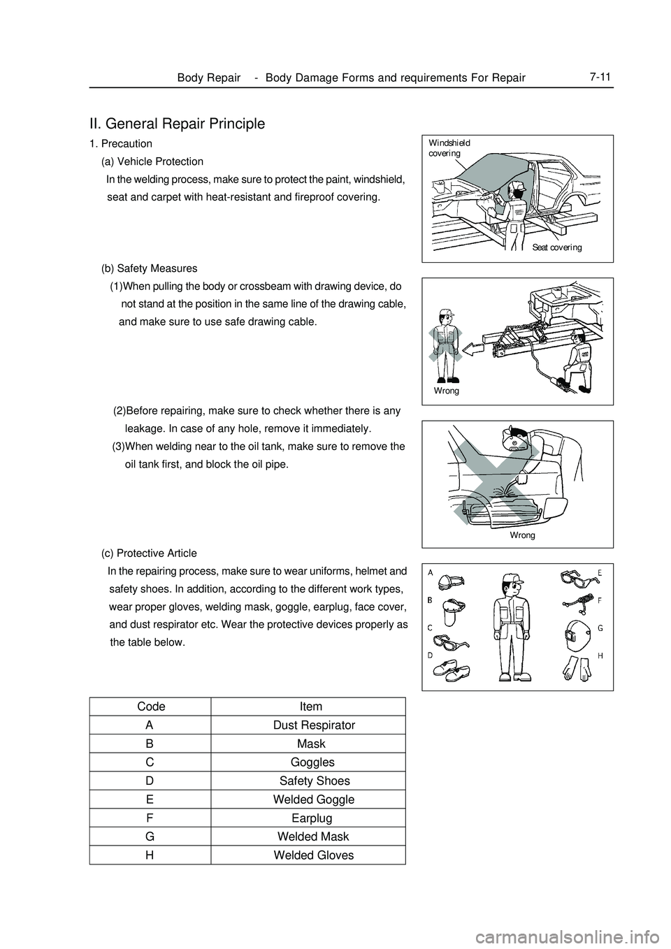
(a) Vehicle Protection
In the welding process, make sure to protect the paint, windshield,
seat and carpet with heat-resistant and fireproof covering.
(b) Safety Measures
(1)When pulling the body or crossbeam with drawing device, do
not stand at the position in the same line of the drawing cable,
and make sure to use safe drawing cable.
(2)Before repairing, make sure to check whether there is any
leakage. In case of any hole, remove it immediately.
(3)When welding near to the oil tank, make sure to remove the
oil tank first, and block the oil pipe.
(c) Protective Article
In the repairing process, make sure to wear uniforms, helmet and
safety shoes. In addition, according to the different work types,
wear proper gloves, welding mask, goggle, earplug, face cover,
and dust respirator etc. Wear the protective devices properly as
the table below.Body Repair -Body Damage Forms and requirements For Repair7-11Seat covering Windshield
coveringWrongWrongItem
Dust Respirator
Mask
Goggles
Safety Shoes
Welded Goggle
Earplug
Welded Mask
Welded Gloves Code
A
B
C
D
E
F
G
H
Page 390 of 416

The cave-in is mainly caused by collision and extrusion. For the light cave-in damage, the metal doesn't extend,
which is plastic deformation. If the collision or extrusion is serious, the metal plate will rupture. For the vehicles
running in the city, it is common that collision damage occurs on the side wall.
d. Bend & Distortion
Bend and distortion belong to mechanical damage. Bend and distortion may have a variety of causes, such as
collision or extrusion, alternating loads generated by the vibration, accident acceleration, emergency brake, sharp
swerve and body torsion caused by poor road.
For the light distortion, it shall be confirmed by test. For the serious bend and distortion, it is obvious in the
appearance. Generally, the distortion can be fixed according to the clearance of the frames and the change of their
relative positions.
e. Unsoldering
The unsoldering is caused by the poor fusion between different metal plates.
2. Outside Plate Repair
a. Repair for Crack
(a) CO2 Welding
The crack on the metal outside plate can be repaired by CO2 welding. In the welding process, align the two
metal plates, and weld the outside crack of the plate first. If the crack doesn't exceed 50mm, the welding shall start
from the rear part of the crack and continue along the crack and edge. If the crack is a little longer, several points
shall be welded first at a certain space. After welding several points, finish them and then weld the crack block
by block. By so doing, it can prevent the metal overroasting and plate deformation caused by too high temperature.
If the crack is located in the position that burden heavy force and it is convenient to carry out the welding operation,
a double-welding method can be used. After the spot welding is made outside, carry out the welding inside. After
the inside welding is completed, make the welding outside in the same manner.
After the welding, put a sizing block inside, and beat from the outside welding line with hammer to removeFig. 5-25 Concave Body Filling Repair b. Repair for Local Damage
For the local corrosion or serious mechanical damage on the outside plate, if it can't be repaired in common
method, the patching or pasting repair method can be used.
Repair Method:
(a). Fix the patching scope;
(b). Cut the paper sample;
(c). Cut the plate as per the sample;
(d). Adhere the molded plate on the surface of the patching part;
(e). Line out the profile along the plate edge with needlepoint, and cut off the damaged or corroded part;Body Repair -Repair After Body Damage7-18the retaining stress. Finally, finish the welding
seam properly to make it even and smooth for
painting.
(b) Solder Filling
For the fine concavo-convex plate with
damage and crack on its surface, it can be re-
paired with a solder filling method. (Fig. 5-25)
Page 391 of 416
(f). Flatten the edge with hammer or sizing block, and remove the burr with file to make sure that it is aligned
with the both side alternative plates with a clearance not more than 1mm;
(g). Replace the plate, and clamp it with pincers. Carry out the spot welding along the seam at a space of
approximately 50mm;
(h). Make the welding from the center to both sides alternately block by block. Which can reduce the
deformation;
(i). Strike the welding line with the hammer or sizing block to remove the retaining stress. Polish the welding
lien wit the file or manual grinding wheel to make it even and smooth for the painting.
c. Repair for Accidented Damage
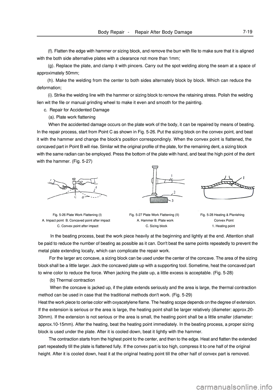
(a). Plate work flattening
When the accidented damage occurs on the plate work of the body, it can be repaired by means of beating.
In the repair process, start from Point C as shown in Fig. 5-26. Put the sizing block on the convex point, and beat
it with the hammer and change the block's position correspondingly. When the convex point is flattened, the
concaved part in Point B will rise. Similar wit the original profile of the plate, for the remaining dent, a sizing block
with the same radian can be employed. Press the bottom of the plate with hand, and beat the high point of the dent
with the hammer. (Fig. 5-27)Fig. 5-27 Plate Work Flattening (II)
A. Hammer B. Plate work
C. Sizing block Fig. 5-26 Plate Work Flattening (I)
A. Impact point B. Concaved point after impact
C. Convex point after impactFig. 5-28 Heating & Planishing
Convex Point
1. Heating pointBody Repair -Repair After Body Damage7-19 In the beating process, beat the work piece heavily at the beginning and lightly at the end. Attention shall
be paid to reduce the number of beating as possible as it can. Don't beat the same points repeatedly to prevent the
metal plate extending locally, which can complicate the repair work.
For the larger arc concave, a sizing block can be used under the center of the concave. The area of the sizing
block shall be a little larger. Jack the concaved plate up with a supporting tool. Sometime, heat the concaved part
to wine color to reduce the force. When jacking the plate up, a little excess is acceptable. (Fig. 5-28)
(b) Thermal contraction
When the concave is jacked up, if the plate extends seriously and the area is large, the thermal contraction
method can be used in case that the traditional methods don't work. (Fig. 5-29)
Heat the work piece to cerise color with oxyacetylene flame. The heating scope depends on the degree of extension.
If the extension is serious or the area is large, the heating point shall be larger relatively (diameter: approx.20-
30mm). If the extension is not serious or the area is small, the heating point shall be a little smaller (diameter:
approx.10-15mm). After the heating, beat the heating point immediately. In the beating process, a proper sizing
block is used under the plate. After it is cooled down, beat it lightly with the hammer.
The contraction starts from the highest point to the center, and then to the edge. Heat and flatten the extended
part repeatedly till the plate is flattened fully. If the convex part is too high, compress it to one half of the original
height. After it is cooled down, heat it at the original heating point till the other half of convex part is removed.