lock GEELY MK 2008 Repair Manual
[x] Cancel search | Manufacturer: GEELY, Model Year: 2008, Model line: MK, Model: GEELY MK 2008Pages: 416, PDF Size: 25.19 MB
Page 255 of 416

5-68Notice
The circuit resistance of the airbag assembly (squib) cannot be measured even with a designated tester.
Since there is current flowing in the squib, when a tester is involved in measuring the resistance, sometimes
the airbag is unexpectedly deployed in case of static electricity, leading to serious accident.
(2) Check the clock spring
Check the following items, and replace the clock spring if any badness is found.
a. Check the connector and protecting tube for damage and the terminal for distortion.
b. Check the case for damage.
c. Check and see if the joint terminal at the upper end of the clock spring are in conduction with that at the
lower end.
d. A thin probe shall be inserted from the back of the yellow connector of the clock spring.
e. With reference to the figure below, insert thin probes into the current tester to check the conduction of the
terminals.VIII. Key points for scrapping the airbag assembly The airbag shall be deployed according to the following procedures before scrapping the airbag assembly or
a vehicle installed with an airbag.
1. Scrapping of an airbag assembly prior to deploymentNotice
The airbag shall be deployed before being scrapped.
The airbag shall be deployed outside the vehicle before being changed.
The airbag shall be deployed in the vicinity of a smoke detector since smoke will appear when the airbag
is deployed.
When being deployed, the airbag will create much noise. People nearby shall wear noise muffler to close
their ears. Avoid do the job within the residential areas.
Deploy inside a vehicle
1) Park the vehicle in a flat area
2) Disconnect the positive (+) and negative (-) terminal cables from the battery and remove the battery from
the vehicle.SRS (Supplemental Restraint System)-
SRS-General Information a. Check the cover for pitting, crack and distortion.
b. Check the connector of the wire harness for damage and the terminal for distortion.
c. Check the case of the gas generator for pitting, crack and distortion.
d. Check the installation status of the airbag assembly. 2. Checking
(1) Driver airbag assembly checking
Check the following items and replace the related components of the airbag assembly if any badness is found.
The old components shall be deployed before scrapping.Notice
If there is pitting, crack or distortion, replace the airbag assembly with new one. The old components of
the airbag shall be deployed before scrapping.
Page 256 of 416

5-69Notice
Work must be started 60s after the positive (+) and negative (-) terminal cables are detached from battery.
3) The airbag assembly shall be deployed according to the following procedures.
(1) Driver airbag assembly
a. Remove the knee bolster.
b. Remove the connector (yellow) that connecting the lower end of the clock spring with the wire harness
of the instrument panel (see the figure below).Notice
Remove the connector of the clock spring from the wire harness of the instrument, the connector will be
short circuited automatically, which can avoid the possible serious accident resulted from the deployment of
the diver airbag assembly due to static electricity.
c. Tie two 6m plus wire harnesses for deployment to the
adaptor wire harness of the airbag, and wrap the connecting points
with insulating tape for insulation.The other ends of the wire harness
for deployment are connected to each other (short circuited). Unex-
pected deployment resulted from static electricity shall be prevented.
d. From the yellow connector of the clock spring, lead the
airbag adapter wire harnesses out of the vehicle by means of the wire
harnesses for deployment (see the figure below).
e. To restrain the noise, close all the windows and doors and
put on the vehicle cover.Notice
The glass will likely break up if there is crack. Vehicle covers shall be put on.
f. Try to disconnect at a location far away from the vehicle the connector of the wire harness for deployment
of the driver airbag assembly, connect them with the two terminals of the battery removed from the
vehicle and deploy the airbag (see the figure below).Notice
Make sure there is no man inside or near the vehicle and then
carry out the operations.
After the driver airbag is deployed, the gas generator is of high
temperature. Keep it for 30 minutes until it gets cool for use.
If the driver airbag assembly cannot be deployed, discuss the
problem with the local Geely service station.Deployed
HarnessCovering the car g. The deployed driver airbag assembly shall be scrapped according to the scrapping procedures.
Deploy outside the vehicleNotice
Keep the airbag over 6m away from a obstacle or person and deploy the airbag in an open flat area.
Deployed the airbag outside the vehicle, avoid to do this job in the strong wind. In case of breeze, fire should
be against the wind.SRS (Supplemental Restraint System)-
SRS-General InformationDAB
Connector Horn
Connector
Page 268 of 416
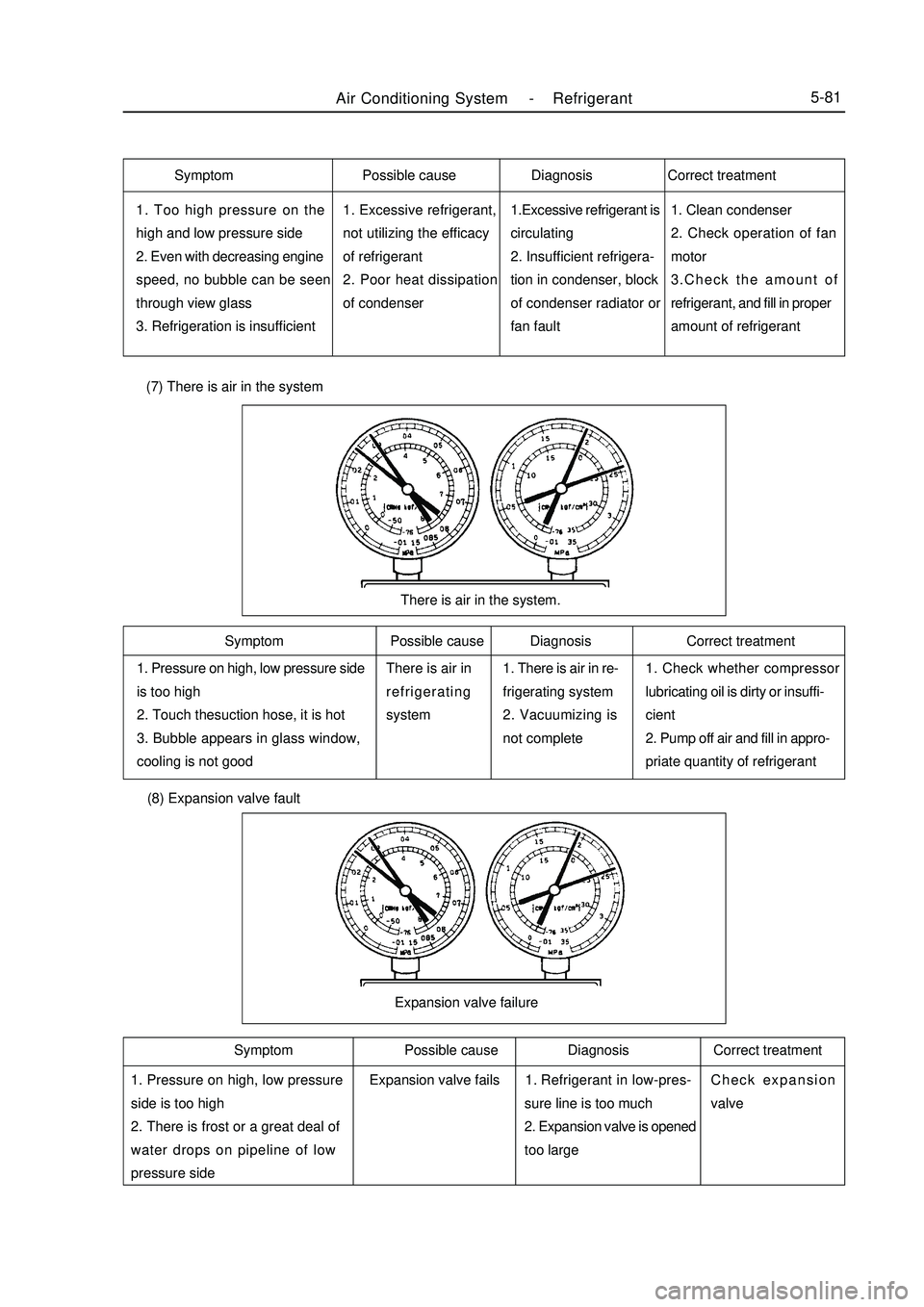
Air Conditioning System -Refrigerant5-811. Too high pressure on the
high and low pressure side
2. Even with decreasing engine
speed, no bubble can be seen
through view glass
3. Refrigeration is insufficient1. Excessive refrigerant,
not utilizing the efficacy
of refrigerant
2. Poor heat dissipation
of condenser1.Excessive refrigerant is
circulating
2. Insufficient refrigera-
tion in condenser, block
of condenser radiator or
fan fault1. Clean condenser
2. Check operation of fan
motor
3.Check the amount of
refrigerant, and fill in proper
amount of refrigerant1. Pressure on high, low pressure side
is too high
2. Touch thesuction hose, it is hot
3. Bubble appears in glass window,
cooling is not goodThere is air in
refrigerating
system1. There is air in re-
frigerating system
2. Vacuumizing is
not complete1. Check whether compressor
lubricating oil is dirty or insuffi-
cient
2. Pump off air and fill in appro-
priate quantity of refrigerantThere is air in the system. (7) There is air in the system (8) Expansion valve fault1. Pressure on high, low pressure
side is too high
2. There is frost or a great deal of
water drops on pipeline of low
pressure sideRefrigerant in low-pres-
sure line is too much
2. Expansion valve is opened
too largeCheck expansion
valveExpansion valve failureSymptom Possible cause Diagnosis Correct treatment
Symptom Possible cause Diagnosis Correct treatment Symptom Possible cause Diagnosis Correct treatment
Expansion valve fails1.
Page 270 of 416

Air Conditioning System -A/C Operating Mechanism5-83Section 3 A/C Operating Mechanism1. Remove heater control and attachment assembly
(1) Remove three control knobs.
(2) Remove two screws and middle instrument board
subassembly.
(3) Loosen six lock catches, pull out heater control and attach
ment assembly
2. Remove the operation mechanism
(1) Loosen the fixed clip (air distributor) and remove the air mit
damper conrol cable.
(2) Loosen the fixed clip (air distributor) and remove air inlet
mode selector cable.:clip:clipClamp
Page 284 of 416

Overhaul1. Drain coolant (refer to Coolant for details).
2. Remove condenser fan motor assembly
(1) Disconnect condenser fan motor wire harness connector.
(2) Unscrew 1 bolt, remove condenser fan motor assembly.
3. Disconnect the liquid tube
(1) Remove the bolt, disconnect the liquid tube from the condenser.
(2) Remove the Oring from the liquid tube.
4. Disconnect the high and low pressure pipe assembly
(1) Remove the bolt, disconnect the high and low pressure tube
assembly from the condenser.
(2) Remove the Oring from the high and low pressure tube
assembly.
Notice: Use vinyl tape seal all the interfaces of the disconnected
parts to avoid entry of water and foreign objects.
5. Remove engine hood lock assembly
(1) remove the bolt, remove engine hood lock assemblyAir Conditioning System -Condenser Fan Motor and Condenser Assembly5-97
Page 287 of 416
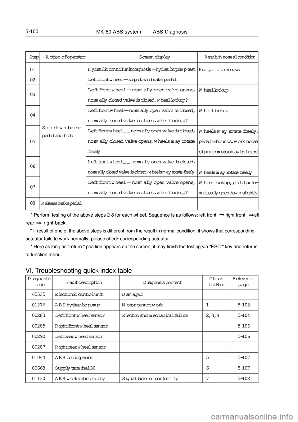
Step Action of operator Screen displayResult in normal conditionPump motor works
Wheel lockup
Wheel lockup
Wheels may rotate freely,
pedal rebounds, work noise
of pump motor may be heard
Wheels may rotate freely
Wheel lockup, pedal auto-
matically goes down slightlyHydraulic control unit diagnosis -- hydraulic pump testLeft front wheel -- step down brake pedal
Left front wheel -- normally open valve opens,
normally closed valve is closed, wheel lockup?
Left front wheel -- normally open valve is closed,
normally closed valve is closed, wheel lockup?
Left front wheel _ _ normally open valve is closed,
normally closed valve opens, wheels may rotate
freelyLeft front wheel _ _ normally open valve is closed,
normally closed valve is closed, wheels may rotate freelyLeft front wheel -- normally open valve opens,
normally closed valve is closed, wheel lockup?
Release brake pedal 01
02
03
04
05
06
07
08Step down brake
pedal and hold
* Perform testing of the above steps 2-8 for each wheel. Sequence is as follows: left front right front left
rear right back.
* If result of one of the above steps is different from the result in normal condition, it shows that corresponding
actuator fails to work normally, please check corresponding actuator.
* Here as long as "return " position appears on the screen, it may finish the testing via "ESC " key and returns
to function menu.VI. Troubleshooting quick index tableMK-60 ABS system - ABS Diagnosis5-100Diagnostic
codeFault description Diagnosis contentCheck
list No.Reference
page
65535
01276
00283
00285
00290
00287
01044
00668
01130Electronic control unit
ABS hydraulic pump
Left front wheel sensor
Right front wheel sensor
Left rear wheel sensor
Right rear wheel sensor
ABS coding error
Supply terminal 30
ABS works abnormallyDamaged
Motor cannot work
Electric and mechanical failure
Signal lacks of conformity5-103
5-104
5-106
5-106
5-107
5-107
5-108 1
2, 3, 4
5
6
7
Page 304 of 416
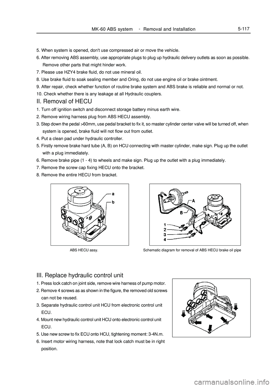
ABS HECU assy.III. Replace hydraulic control unit1. Press lock catch on joint side, remove wire harness of pump motor.
2. Remove 4 screws as as shown in the figure, the removed old screws
can not be reused.
3. Separate hydraulic control unit HCU from electronic control unit
ECU.
4. Mount new hydraulic control unit HCU onto electronic control unit
ECU.
5. Use new screw to fix ECU onto HCU, tightening moment: 3-4N.m.
6. Insert motor wiring harness, note that lock catch must be in right
position.MK-60 ABS system -
Removal and Installation5-117Schematic diagram for removal of ABS HECU brake oil pipe5. When system is opened, don't use compressed air or move the vehicle.
6. After removing ABS assembly, use appropriate plugs to plug up hydraulic delivery outlets as soon as possible.
Remove other parts that might hinder work.
7. Please use HZY4 brake fluid, do not use mineral oil.
8. Use brake fluid to soak sealing member and Oring, do not use engine oil or brake ointment.
9. After repair, check whether function of routine brake system and ABS brake is reliable and normal or not.
10. Check whether there is any leakage at all Hydraulic couplers.II. Removal of HECU1. Turn off ignition switch and disconnect storage battery minus earth wire.
2. Remove wiring harness plug from ABS HECU assembly.
3. Step down the pedal >60mm, use pedal bracket to fix it, so master cylinder center valve will be turned off, when
system is opened, brake fluid will not flow out from outlet.
4. Put a clean pad under hydraulic controller.
5. Firstly remove brake hard tube (A, B) on HCU connecting with master cylinder, make sign. Plug up the outlet
with a plug immediately.
6. Remove brake pipe (1 - 4) to wheels and make sign. Plug up the outlet with a plug immediately.
7. Remove the screw cap fixing HECU onto the bracket.
8. Remove the entire HECU from bracket.
Page 305 of 416
V. Reinstallation of ABS assemblyNote: plug of hydraulic opening on ABS assembly may be removed only when brake hard tube is to be installed,
so as to avoid foreign body entering brake system
1. Mount ABS assembly to bracket and tighten it, moment is 20~24 N.m.
2. Remove the plug on hydraulic opening, mount brake hard tube, confirm that hard tube connection is correct.
3. Mount brake hard tube to master cylinder.
4. Tightening moment for assembly of brake hard tube is 12~16N.m (M10 x 1) and 15~18 N.m (M12 x 1).
5. Fill new brake fluid into tank until liquid level reaches MAX place, use specified method to exhaust.
6. Turn ignition switch to ON, ABS warning lamp must illuminate for 1. 7s, then go out.
7. Eliminate fault code memory, reread to see whether there is any fault code.
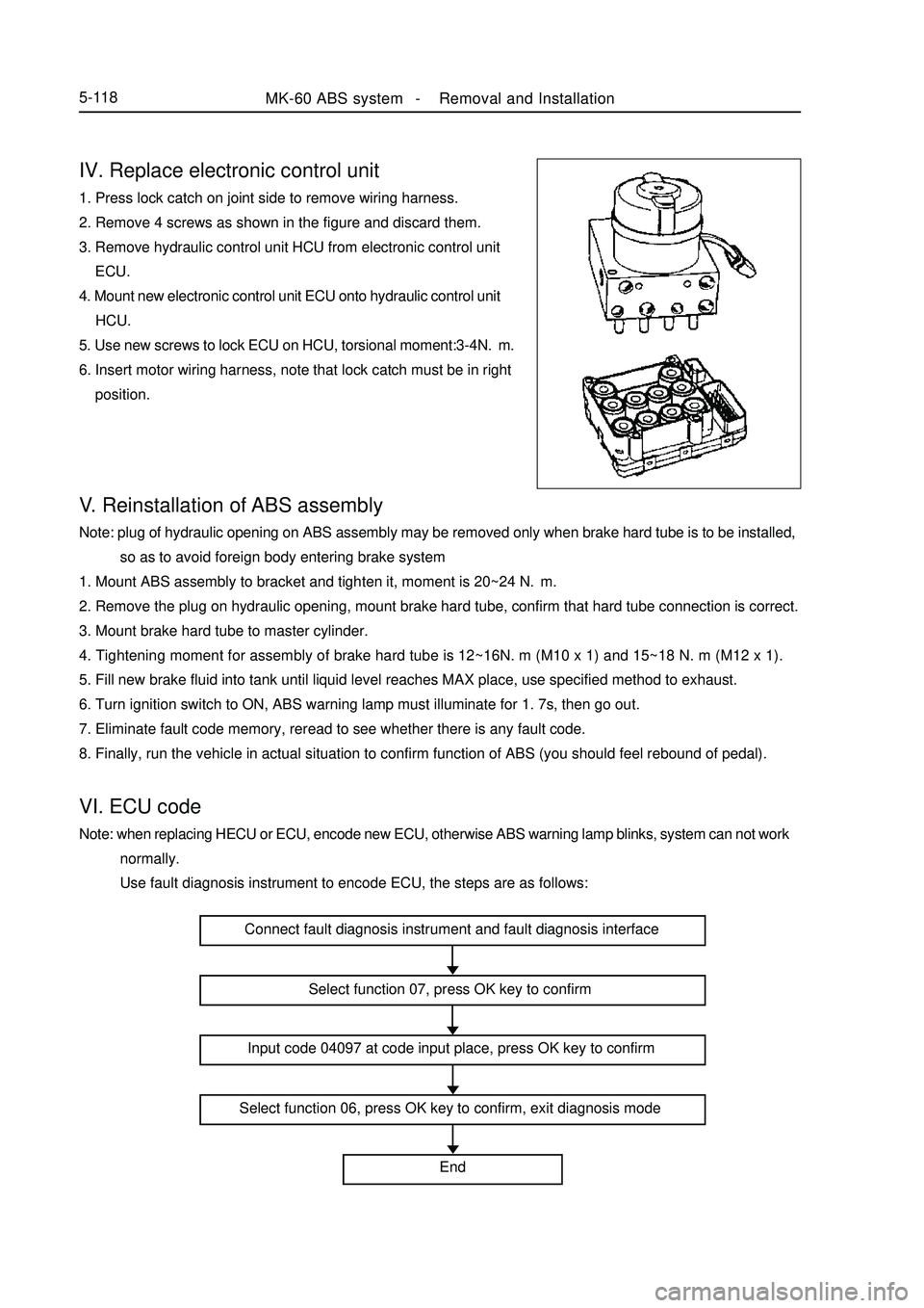
8. Finally, run the vehicle in actual situation to confirm function of ABS (you should feel rebound of pedal).VI. ECU codeNote: when replacing HECU or ECU, encode new ECU, otherwise ABS warning lamp blinks, system can not work
normally.
Use fault diagnosis instrument to encode ECU, the steps are as follows:IV. Replace electronic control unit1. Press lock catch on joint side to remove wiring harness.
2. Remove 4 screws as shown in the figure and discard them.
3. Remove hydraulic control unit HCU from electronic control unit
ECU.
4. Mount new electronic control unit ECU onto hydraulic control unit
HCU.
5. Use new screws to lock ECU on HCU, torsional moment:3-4N.m.
6. Insert motor wiring harness, note that lock catch must be in right
position.MK-60 ABS system -Removal and Installation5-118Connect fault diagnosis instrument and fault diagnosis interface
Select function 07, press OK key to confirm
Input code 04097 at code input place, press OK key to confirm
Select function 06, press OK key to confirm, exit diagnosis mode
End
Page 309 of 416
4. Knocking sensor
(1) Knocking sensor is a vibration acceleration sensor. Mounted on engine cylinder body. Sensing element of
the sensor is a piezocrystal. Vibration of engine cylinder body is transferred to piezocrystal via mass block in the
sensor. Since pressure generated by vibration of mass block is applied to piezocrystal, it generates voltage on two
polar planes and turns vibration signal into voltage signal for output.5-122Symptom
Poor accelerationPossible cause
Various liquids, such as engine oil, cooling fluid, brake fluid, water etc
contact the sensor for a long time, which cause corrosion to the sensor. Mounting torque: 20 ± 5 N.M
Repair precautions: sensor must be fitted closely to cylinder body with its metal surface, any type of washer
is not permitted for installation. For wiring of sensor signal cables, note that do not let resonance occur to signal
cables, otherwise they might be broken. Energizing of high voltage between sensor 1 # and 2 # pins must be
avoided, otherwise piezoelectric element might be damaged.
(2) Simple measuring method:
(Remove joint) turn digital multimeter to ohm position, connect two meter pens with sensor 1 #, 2 # pin
respectively, its resistance value at room temperature should exceed 1M ohm. Turn digital multimeter to millivolt
position, use a hand hammer to tap near knocking sensor, now voltage signal output should be available.
5. Oxygen sensor
(1) Its sensing element is a ceramic tube, outside is open to exhaust, inside is open to atmosphere. When
temperature of sensing ceramic tube reaches 350°C, it will have the characteristic of solid state electrolyte. Just
utilizing this characteristic, it converts concentration difference of oxygen into electric potential difference, thus
forms electrical signal output. If mixed gas is a bit concentrated, inside and outside oxyanion concentration
difference of ceramic tube is high, electric potential difference is a bit high.
A large number of oxyanions move from inside to outside, output voltage is high (approximate 900mV); if
mixed gas is a bit thin, inside and outside oxyanion concentration difference of ceramic tube is low, electric
potential difference is low, only a small quantity of oxyanions move from inside to outside, output voltage is low
(approximate 100mV).
Possible cause
1. humid water vapor ingresses inside of sensor, temperature
changes rapidly, probe is broken.
2. oxygen sensor "is poisoned". (Pb, S, Br, Si) Symptom
Poor idle speed, poor speedup, tail gas
overproof, too high oil consumption1 2 3 4Oxygen sensor Mounting torque: 40-60 N.m
Repair precautions: it is prohibited to use cleaning fluid, oily liquid or volatile solid on oxygen sensor during
repair.
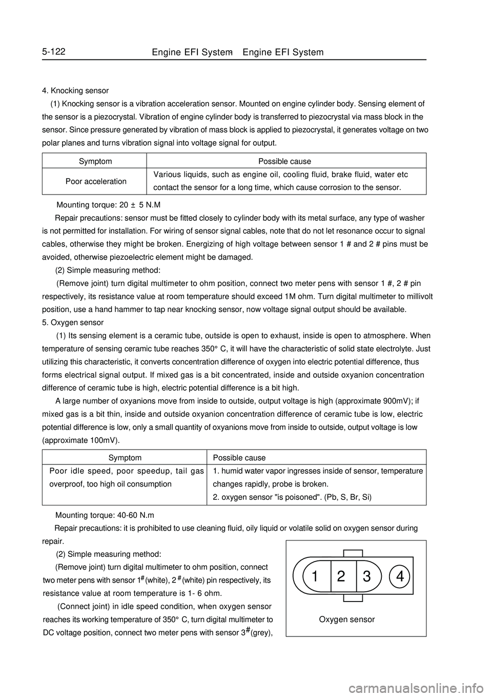
(2) Simple measuring method:
(Remove joint) turn digital multimeter to ohm position, connect
two meter pens with sensor 1# (white), 2# (white) pin respectively, its
resistance value at room temperature is 1- 6 ohm.
(Connect joint) in idle speed condition, when oxygen sensor
reaches its working temperature of 350°C, turn digital multimeter to
DC voltage position, connect two meter pens with sensor 3# (grey),Engine EFI System-Engine EFI System
Page 310 of 416

Symptom Possible cause
Fail to start Man made faultSpeed sensor1 2 3Fault symptom Common cause
Dischrge overproof, increased oil consumption Man made fault5-1234#(black) pin respectively, now voltage should fluctuate quickly between 0. 1-0. 9V.
6. Speed sensor
(1) Use with oscillator. Oscillator is a fluted disc, originally has 60 teeth, but two teeth are absent. Oscillator
is mounted on crankshaft, and rotates with the crankshaft. When tooth tip passes by sensor end closely, the
oscillator which is made of ferromagnetic material cuts magnetic line of permanent magnet in the sensor, and
generates induced voltage in coil, which is output as rotating speed signal. Mounting torque: 8 ± 2 N.m
Repair precautions: use pressing in instead of hammering method for installation during repair.
(2) Simple measuring method:
(Remove joint) turn digital multimeter to ohm position, connect
two meter pens with sensor 2#, 3# pins respectively, rated resistance
at 20°C is 770-950 ohm.
(Connect joint) turn digital multimeter to AC voltage position,
connect two meter pens with sensor 2 #, 3# pins respectively, start up
engine, now voltage output should be available.
Suggestion: use oscillograph for vehicle use to check.
7. Phase sensor
(1) This sensor consists of a hall sensor and a rotor made of steel plate. Fix hall sensor, mount rotor on camshaft.
Rotor is a 180( range cylindrical face steel blade. When the blade covers hall sensor, high Level signal is output;
otherwise low level signal is output. This differentiates two different upper dead points. Repair precautions: avoid removing end cover as far as possible during repair, so as to avoid ingress of foreign
matter, which might result in abnormal damage of magnetic gate.
(2) Simple measuring method:
(Connect joint) turn on ignition switch but not start up engine, turn digital multimeter to DC voltage position,
connect two meter pens with sensor red, black conductors respectively, ensure reference voltage of 5V is available.
Start up engine, voltage output between green and black conductors should be available.
Suggestion: use oscillograph for vehicle use to check.
8. Idle speed regulator
(1) Idle speed regulator consists of a step motor and a sealing plug on its shaft, sealing plug may generate radial
displacement driven by step motor shaft, position of sealing plug determines extent of opening of by-pass airway,
so as to adjust the size of by-pass air quantity. Position of sealing plug is controlled by ECU output.Fault symptom
Too high idle speed, flameout at idle speedPossible cause
Since interior contamination is severe, regulating element
is blocked and leads to malfunction.
Repair precautions: dust and sand grain will result in damage of idle speed regulator. Intake air should be
filtered by dry air cleaner before entering idle speed regulator, filtration efficiency should exceed 99 %. ToEngine EFI System-Engine EFI System