engine GEELY MK 2008 Workshop Manual
[x] Cancel search | Manufacturer: GEELY, Model Year: 2008, Model line: MK, Model: GEELY MK 2008Pages: 416, PDF Size: 25.19 MB
Page 374 of 416

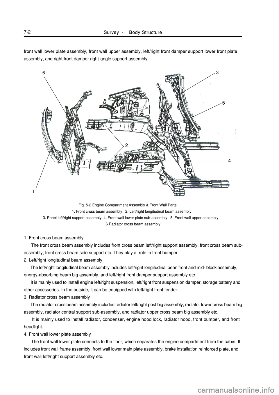
1. Front cross beam assembly
The front cross beam assembly includes front cross beam left/right support assembly, front cross beam sub-
assembly, front cross beam side support etc. They play a role in front bumper.
2. Left/right longitudinal beam assembly
The left/right longitudinal beam assembly includes left/right longitudinal bean front and mid- block assembly,
energy-absorbing beam big assembly, and left/right front damper support assembly etc.
It is mainly used to install engine left/right suspension, left/right front suspension damper, storage battery and
other accessories. In the outside, it can be equipped with left/right front fender.
3. Radiator cross beam assembly
The radiator cross beam assembly includes radiator left/right post big assembly, radiator lower cross beam big
assembly, radiator central support sub-assembly, and radiator upper cross beam big assembly etc.
It is mainly used to install radiator, condenser, engine hood lock, radiator hood, front bumper, and front
headlight.
4. Front wall lower plate assembly
The front wall lower plate connects to the floor, which separates the engine compartment from the cabin. It
includes front wall frame assembly, front wall lower main plate assembly, brake installation reinforced plate, and
front wall left/right support assembly etc.Fig. 5-2 Engine Compartment Assembly & Front Wall Parts
1. Front cross beam assembly 2. Left/right longitudinal beam assembly
3. Panel left/right support assembly 4. Front wall lower plate sub-assembly 5. Front wall upper assembly
6 Radiator cross beam assemblySurvey -Body Structure7-2123456front wall lower plate assembly, front wall upper assembly, left/right front damper support lower front plate
assembly, and right front damper right-angle support assembly.
Page 375 of 416

It is mainly used to install the pipes and accessories of the brake system and clutch system.
5. Front wall upper assembly
The front wall upper assembly includes left/right hinge base mounting plate big assembly, front wall upper
front cover big assembly, VIN number mounting plate, and front wall upper rear cover big assembly etc.
It forms a high-stiffness frame structure together with the engine compartment assembly and the front wall
lower plate assembly. It can generate strong resistant to the transverse collision and rolling deformation. It can also
separate the engine compartment form the cabin, preventing the odor entering into the cabin. Consequently, it can
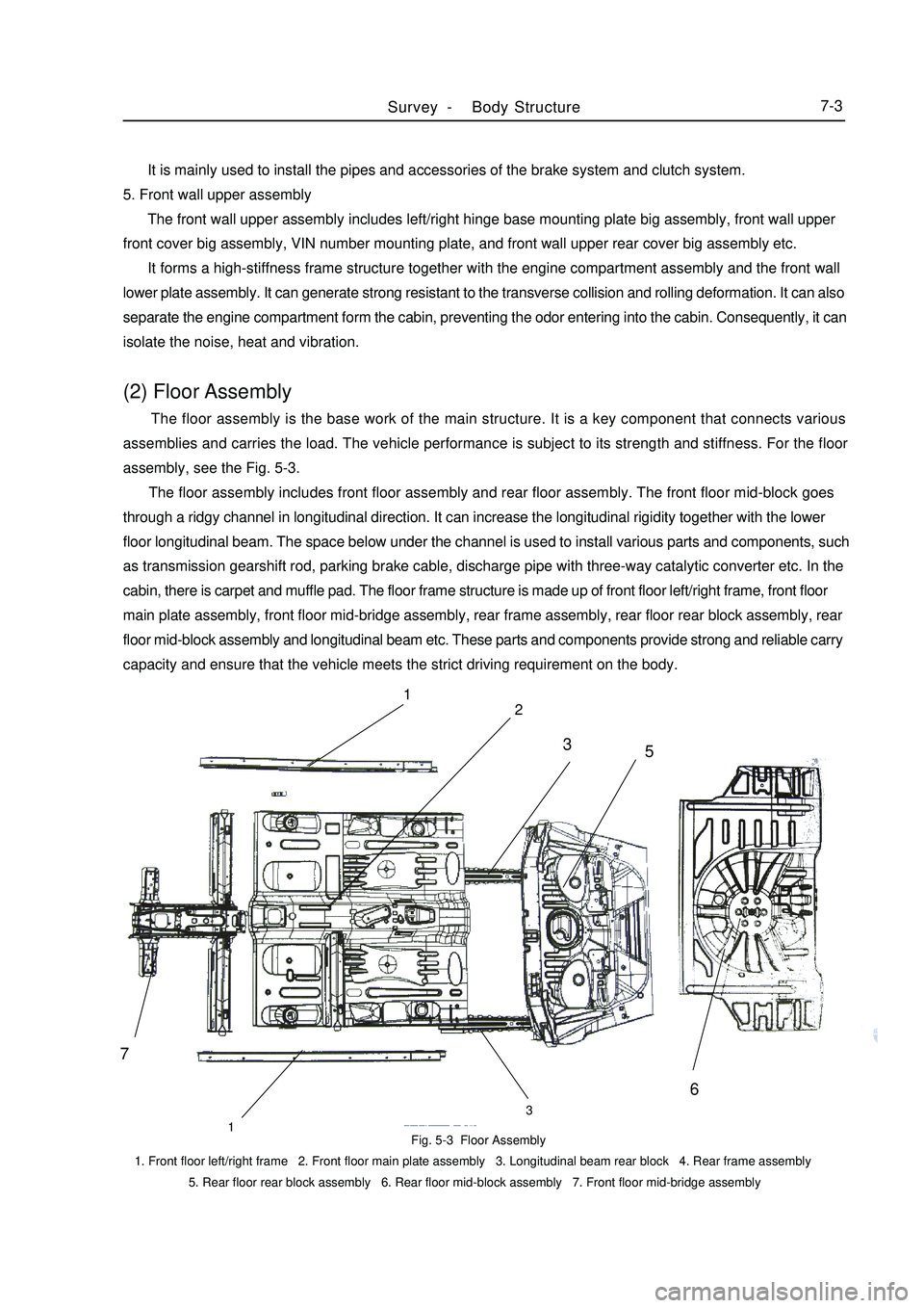
isolate the noise, heat and vibration.(2) Floor Assembly The floor assembly is the base work of the main structure. It is a key component that connects various
assemblies and carries the load. The vehicle performance is subject to its strength and stiffness. For the floor
assembly, see the Fig. 5-3.
The floor assembly includes front floor assembly and rear floor assembly. The front floor mid-block goes
through a ridgy channel in longitudinal direction. It can increase the longitudinal rigidity together with the lower
floor longitudinal beam. The space below under the channel is used to install various parts and components, such
as transmission gearshift rod, parking brake cable, discharge pipe with three-way catalytic converter etc. In the
cabin, there is carpet and muffle pad. The floor frame structure is made up of front floor left/right frame, front floor
main plate assembly, front floor mid-bridge assembly, rear frame assembly, rear floor rear block assembly, rear
floor mid-block assembly and longitudinal beam etc. These parts and components provide strong and reliable carry
capacity and ensure that the vehicle meets the strict driving requirement on the body.Fig. 5-3 Floor Assembly
1. Front floor left/right frame 2. Front floor main plate assembly 3. Longitudinal beam rear block 4. Rear frame assembly
5. Rear floor rear block assembly 6. Rear floor mid-block assembly 7. Front floor mid-bridge assemblySurvey -Body Structure7-371
2
133
5
6
Page 378 of 416

Fig. 5-7 Luggage Compartment Main
Cover Assembly
1. Luggage compartment main cover
2. Rear seat hook mounting plate assembly
3. Left/right side angle plate
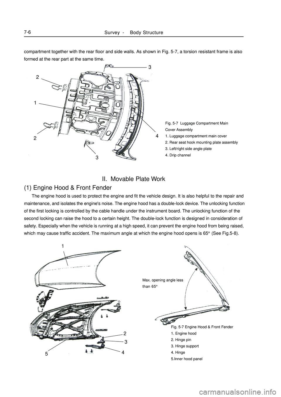
4. Drip channelII. Movable Plate Work(1) Engine Hood & Front Fender The engine hood is used to protect the engine and fit the vehicle design. It is also helpful to the repair and
maintenance, and isolates the engine's noise. The engine hood has a double-lock device. The unlocking function
of the first locking is controlled by the cable handle under the instrument board. The unlocking function of the
second locking can raise the hood to a certain height. The double-lock function is designed in consideration of
safety. Especially when the vehicle is running at a high speed, it can prevent the engine hood from being raised,
which may cause traffic accident. The maximum angle at which the engine hood opens is 65°(See Fig.5-8).Fig. 5-7 Engine Hood & Front Fender
1. Engine hood
2. Hinge pin
3. Hinge support
4. Hinge
5.Inner hood panelSurvey -Body Structure7-642
3
51Max. opening angle less
than 65°compartment together with the rear floor and side walls. As shown in Fig. 5-7, a torsion resistant frame is also
formed at the rear part at the same time.3
4
213 2
Page 379 of 416

(2) Front FenderFront fender plays a role in front wheel apron and rotect person safty.And at the same tirne,if also woork as vehicle
styling parts.
For the match relationship between the front fender & engine hood and the front door, see Fig. 5-9.Fig. 5-9 Front Fender related to surrounding parts
A) With Engine Hood (4mm¡À1mm)
B) With Front Door (5mm¡À1mm)(3) Door Assembly Doors have LH/RH front door and rear door.
The door uses hinge gemel with limiting device, which is an open structure.
The door includes door outside plate, door inside plate, bumper and hinge reinforced plate etc.
The door has a complex structure, which is a movable component on the body. It helps the passengers get on/
off the vehicle and form an enclosed cabin with the main structure and the relevant parts. Meanwhile, the doors
are used frequently, so there is high requirement on their reliability and durability.
The outside/inside plate is molded by one complete steel sheet, which can improve the stiffness and precision.
In order to improve the safety when the vehicle is collided from the side, four doors are equipped with door
bumpers.
As shown in Fig. 5-10 and Fig. 5-11, the door assembly is made up of outside plate assembly and inside plate
assembly.Fig. 5-10 Front Door
1. Front door inner panel 2. Left front door inner reinforced panel 3. Front door window opper rail 4. Door lock reinforced panel
5. Left front door inner plate cross beam 6. Front door outer panel 7. Door bumper assembly
8. Front door upper hinge assembly 9. Front door lower hinge assembly 10. Hinge reinforced panel assemblySurvey -Body Structure7-7Engine hood
Front fenderFront door
Front fenderA
B12345678910
Page 381 of 416

Chapter 2 Body RepairSection 1 Body Damage Forms and requirements For RepairI. Damage Type The damage type includes deformation, crack, rust-through, water leakage, dust leakage and the like caused
by collision, overload, fatigue, and corrosion.
The body damage is not merely caused by the huge force. As some parts (such as door etc.) are damaged, the
vehicle stays in an abnormal status, which also can cause damage. In most cases, the bend and torsion is caused
by huge local load in the impact or turnover accident.
Typical Body Damage:
1. Front Center Collision (Fig. 5-13)Fig. 5-13 Front Center CollisionBody Repair -Body Damage Forms and requirements For Repair7-9 For the damage caused by the collision on the front center, it usually makes the engine compartment front part
and the engine hood left/right side extend inwards so the following positions shall be checked:
a. Ambience of the left/right assembling position of the hood plate
b. Ambience of the joints of the front cross beam and the left/right longitudinal beam
2. Front External Force or Left External Force (Fig. 5-14)Fig. 5-14 Front External Force or Left External Force As shown in Fig. 5-14, when the front is pressed or the left side end is acted by the external force, the external
force will spread to around the front suspension mounting position from the left/right side of the hood, so
deformation occurs easily in this position.
Page 385 of 416

Plate Thickness Hole Diameter
<1.0 >5
1.0~1.5 >6.4
>1.5 >87-13 (b) Apply special paint for spot welding
Remove the paint film from the new parts to be welded and the
body, and apply the special paint for spot welding.
(c) Bore for hole-filling welding
In the position that can not carry out the spot welding, bore it
with borer or bit to make hole-filling welding.
Unit: mm
(d) Precaution for electronic parts
(1) In the welding process, the electronic parts may be damaged
due to the current in the body.
(2) Before the welding, cut the cathode connection of the
storage battery, and put the ground end of the welder on the
ambiance of the welding area.
(e) Rough cutting of joint parts
In the rough cutting process in the connecting area, an overlap
of 20~30mm must be reserved on the new parts.
3. Installation
(a) Measure before Welding
Before installing the lower body or the parts of the engine
compartment, make sure to make measurement as the body
dimension drawing, to ensure the correctness. After the
installation, reconfirm whether the assembling is proper.Hole filling
Overlap
Pneumatic saw
Body dimension
drawingBody Repair -Body Damage Forms and requirements For Repair
Page 386 of 416

7-14 (b) Precaution
(1) For the number of spot welding, it depends on the following
principles.
S pot welding:1.3 times of the number specified by the manufacturer
Hole-filling welding: more than the number specified by the
manufacturer
(2) When carrying out the hole-filling welding, MIG welder
shall be used. It is not allowed to use the oxyacetylene
welding or braze welding outside the specified area.
(c) Abrasion after welding
(1) After the welding, make sure to check the welding position
whether it is welded firmly.
(2) When abrading the welding position with disc abrader,
never abrade it too much, which may weakens the strength
of the welding position.
(d) Precaution of spot welding
(1) The shape of the spot welder head may affect the strength
of the welding.
(2) Make sure to remove the paint film on the surface of the spot
welding and the contact surface of the welder head.
(e) Position of spot welding
In the spot welding process, overlap with the old welding
position shall be avoided.
4. Anti-rust Processing
(a) Apply sealant
In the waterproof and antirust part operation, make sure to
apply the sealant on the joint of the steel plates,door,and engine
hood corner.Wrong CorrectWrong
Spot welding head scraper
New welding position
Old welding
positionSealant gunBody Repair -Body Damage Forms and requirements For Repair
Page 387 of 416

5. Base Anti-rust Processing
Impact-proof Coat
In order to avoid corrosion and protect the body from being damaged by bouncing stone on the road, a layer
of impact-proof coat is applied on the door threshold plate, arc area and balancing plate etc.
Tips: There are two types of painting: impact-resistant coat on the electrophoresis primer or on the surface paint
according to different types and painting positions. (See Fig.5-22)7-15IV. Repair Requirement 1. As the body is an integral structure and the steel plates used are not thick, special attention shall be paid to
reinforce the parts acted in the reshaping process in the plate work processing. For the parts that burden the stress
intensively, measures shall be taken to lower the local stress.
2. After the plate work processing, note to apply the antirust primer on the inside and outside surfaces to avoid
corrosion.
3. In the body repair process, repair the old parts; or remove the parts with serious defects and order new parts
from the manufacturer.
4. When making body reshaping or parts welding, make sure that all main control points of the body are within
the specified scope in the design.
5. The strength and serviceability of the repaired body shall not be lower than those of the new vehicle.
6. The outside decoration of the repaired body shall meet the requirements by the new vehicle body and the
drivers in various aspects, such as modern aesthetics and ergonomics etc. (b) Apply primer
In order to prevent rust and protect the body steel plate from
being damaged by the bouncing stone, sufficient primer is
applied onto the body base and inner wheel cup.
(c) Apply antirust (wax)
In order to prevent the painting part from rusting, sufficient
antirust is applied on the engine cover, door inner corner, hinge
ambiance, or in the inside welding part of the box section
structures such as side beam, body post.Fig. 5-22 Apply the impact-proof coat on the surface paint
Impact-proof coat
Surface paint
Intermediate primer
Electrophoresis primer
Steel sheet Apply the impact-proof coat on the electrophoresis primer
Surface paint
Intermediate primer
Impact-proof coat
Electrophoresis primer
Steel sheetBody Repair -Body Damage Forms and requirements For Repair
Page 396 of 416

1. Material of Punch Piece
In order to improve the body's rigidity, high-strength steel plates are used at many key parts on the body. For
the parts under forces, reinforced measures are carried out. (Fig. 5-36)Fig. 5-36 High-strength Steel Panel
1. Engine compartment hood outside panel
2. Left/right fender
3. Left/right mid-door post inside panel
4. Luggage cover outside panel
5. Left/right door outside panel12
3
45Body Repair -Features and Composition of Automobile Body7-24Fig. 5-35 Outline & DimensionsSection 4 Features and Composition of Automobile BodyI. Body Feature The body is an integral structure. Its main structure also is a frame, which can carry all loads. The vehicle is
designed with three compartments and five doors. With the same overall length, the space is utilized fully, which
is helpful to arrangement of passengers. (Fig. 5-35)
14351431
1934.5 1450
4343 848 2502 992
Page 397 of 416

2. Shock Absorption & Noise Isolation
(1) Body structure (Fig. 5-37)
a. Arrange the reinforced bar reasonably to improve the parts' rigidity, reduce the shock and lower the noise.
b. Apply the sealant in the floor seam to improve the floor sealing and reduce the noise in the cabin.Fig. 5-37 Front Wall Panel
1. Front wall bridge reinforced panel
2. Front wall mid-frame panel
3. Front wall lower main panel
4. Heat-isolated pad
Fig. 5-38 (a) Body floor
1. Front mud guard 2. Rear side wall 3. Rear wheel housing 4.Floor sides (2) Deadening
It is an interactive and systemic work to make the body isolate heat, shock and noise. Besides the measures
carried out to improve the body's stiffness and sealing performance, the following measures shall be taken in the
design and manufacture process.
a. Sound isolation material: add sound isolation pad on the front wall and floor.
b. Sound absorption material: add molded carpet on the front floor and rear floor.
3. Sealing
Special consideration has been given to the sealing of the body both in design process and in manufactureprocess. Sealing plays an important role in many aspects, such as dust resistance, water resistance, corrosionresistance, heat resistance, heat preservation, and noise reduce etc. Especially when the body floor and front wall
stay in a tough external condition, the mud, dust, noises (from the tire and engine) and hot air will invade into the
cabin any time.
After the body assembly is welded, sealant will be employed on all joints to prevent the water and steam
penetrating into the metal seam and ensure the quality of subsequent painting.
In addition, a thick layer of impact-proof PVC coat is applied on the base of the body, which has excellentsealing performance. For the sealing to those assemblies, the traditional sealing method is used, such as rubber sealBody Repair -Features and Composition of Automobile Body7-251
123Front4