GEELY MK 2008 Workshop Manual
Manufacturer: GEELY, Model Year: 2008, Model line: MK, Model: GEELY MK 2008Pages: 416, PDF Size: 25.19 MB
Page 131 of 416

Component ViewUpper washer
Left rear
helical spring
Lower washer Rear shock absorber assembly Right rear helical spring
Left rear helical spring
Lower washer829.09849Chapter 6 Rear Suspension SystemSection 1 Rear Suspension SystemLoad-sensing valve
bracketRear supension crossmemberRear Suspension System-Rear Suspension System4-54specified torqueN.
m :With ABS
Side slip control sensor wire
Washer
Clip Brake hose
Brake hoseNon-reusable parts
Page 132 of 416

I. Rear suspension structure description This model uses strut independent rear suspension with stabilizer bar.
Rear suspension consists of the parallel front and rear double transverse arms, trailing rod, rear stabilizer bar
and rear strut assembly. The shock absorber and cone coil spring are arranged eccentrically.
See the table below for the major technical parameters of the rear suspensionII. Symptom Table Use the table below to help you find the cause of the problem. The numbers indicate the priority of the likely
cause of the problem. Check each part in order. If necessary, replace these parts.Suspected Area
1. Tires (Worn or improperly inflated)
2. Wheel alignment (Incorrect)
3. Hub bearing (Worn or damaged)
4. Suspension parts (Worn or damaged)
1. Vehicle (Overloaded)
2. Spring (Stiffness small)
3. Shock absorber (Worn)
1. Tire (Worn or improperly inflated)
2. Wheel (not within specification)
3. Shock absorber (Worn)
1. Tire (Worn or improperly inflated)
2. Wheel alignment (Incorrect)
3. Shock absorber (Worn)
4. Wheel (not within specification)
1. Tire (Worn or improperly inflated)
2. Wheel alignment (Incorrect)
3. Shock absorber (Worn)
4. Suspension parts (Worn or damaged)Symptom
Off track
Body descent
Sways
Rear wheel shimmy
Abnormal tire wearRear Suspension System-Rear Suspension System4-55Item
Shock absorber operating cylinder diameter /mm
Shock absorber piston rod diameter/mm
Shock absorber stroke /mm
Camber
Toe in/mm
Remark: Wheel alignment parameter is at free loadParameter
38
12.4
250
-0°56' ± 45'
3 ± 3
Page 133 of 416

Check1. Check the tire
2. Measure the vehicle height
Notice:
Adjust the vehicle height to specified value before check the
wheel alignment
3. Check the rear toe-inSection 2 Rear Wheel AlignmentRear Suspension System-Rear Wheel Alignment4-56A+B: 0°19' ± 19' (0.31 ± 0.31°)
C+D: 3.0 ± 3.0mmToe in
( assembly ) Check and replace the related suspension parts if the toe in out of spec.
4. Check the camber
(1) Mount the camber-caster-kingpin measuring device, place the vehicle on the wheel position device
(2) Check camber
Check the damage and performance decline of suspension parts and replace if necessary, if measurement out
of spec.-0°56' ± 45' (-0.93° ± 0.75°)
45' (0.75°) or smallerCamber
Left-right deviationFront
Page 134 of 416

Section 3 LH/RH Rear Suspension Coil SpringReplacement1. Remove rear wheel
2. Remove the wire of the wheel speed sensor(with ABS)
(1) Remove the connector of wheel speed sensor.
(2) Remove bolts and wheel speed sensor from rear axle
frame.
Notes:
Remove the right sensor wire by using same process as left.
3. Remove the load-sensing valve bracket (without ABS)
Remove two nuts and load-sensing valve bracket from the axle
bracket
4. Remove the proportioning valve and rear right brake tube
(1) Remove the proportioning valve and rear right brake tube by
the special tool
(2) Remove the clips
Notes: Don't reuse the clips
5. Remove the proportioning valve and rear left brake tube
Notes: use the same operations of the proportioning valve and
rear right brake tube to remove #3 rear brake tube.
6. Remove right parking brake cable assembly
Remove nuts and right parking brake cable assembly
assembly from rear axle frame
7. Remove left parking brake cable assembly
8. Loose the rear axle assembly
Loose two 2 boltsRear Suspension System-LH/RH Rear Suspension Coil Spring4-57
Page 135 of 416

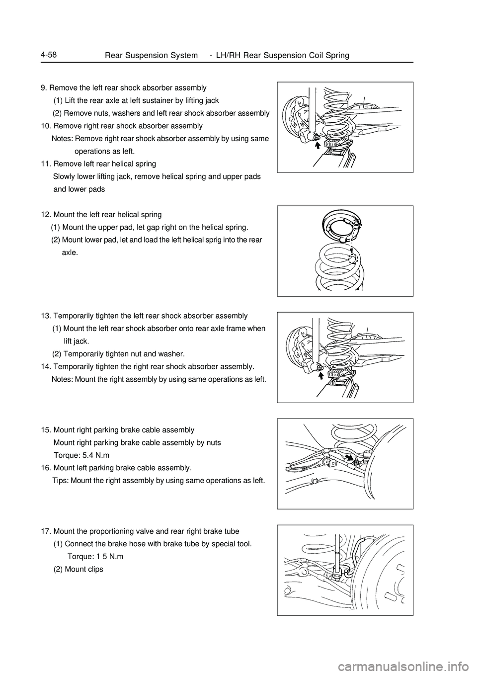
9. Remove the left rear shock absorber assembly
(1) Lift the rear axle at left sustainer by lifting jack
(2) Remove nuts, washers and left rear shock absorber assembly
10. Remove right rear shock absorber assembly
Notes: Remove right rear shock absorber assembly by using same
operations as left.
11. Remove left rear helical spring
Slowly lower lifting jack, remove helical spring and upper pads
and lower pads
12. Mount the left rear helical spring
(1) Mount the upper pad, let gap right on the helical spring.
(2) Mount lower pad, let and load the left helical sprig into the rear
axle.
13. Temporarily tighten the left rear shock absorber assembly
(1) Mount the left rear shock absorber onto rear axle frame when
lift jack.
(2) Temporarily tighten nut and washer.
14. Temporarily tighten the right rear shock absorber assembly.
Notes: Mount the right assembly by using same operations as left.
15. Mount right parking brake cable assembly
Mount right parking brake cable assembly by nuts
Torque: 5.4 N.m
16. Mount left parking brake cable assembly.
Tips: Mount the right assembly by using same operations as left.
17. Mount the proportioning valve and rear right brake tube
(1) Connect the brake hose with brake tube by special tool.
Torque: 1 5 N.m
(2) Mount clipsRear Suspension System-LH/RH Rear Suspension Coil Spring4-58
Page 136 of 416

Rear Suspension System-LH/RH Rear Suspension Coil Spring4-5918. Mount rear right brake tube
Tips:
Mount the right assembly by using same operations as left.
19. Mount sideslip control sensor wire (with ABS)
(1) Tighten sideslip control sensor wire by bolts
Torque: 8.0 N.m
(2) Mount sideslip control sensor wire
Attention: Mount the right wire by using same operations as left.
20. Mount load-sensing valve bracket (without ABS)
Mount load-sensing valve bracket by two buts
21. Sufficiently tighten the rear axle frame assembly
(1) Stabilize the shock absorber assembly
Use the lifting jack and add 90Kg force on rear luggage
carrier if bolts can not be tightened at this point.
(2) Sufficiently tighten bolts
Torque: 82 N.m
22. Sufficiently tighten the left rear shock absorber assembly
Sufficiently tighten nuts
Torque: 49 N.m
23. Sufficiently tighten the right rear shock absorber assembly
Tips: Mount the right rear shock absorber by using same opera-
tions as left.
24. Release the air in the brake hose
25. Mount the rear wheel
Torque: 103 N.m
26. Check rear the wheel alignment
27. Check the wheel speed sensor signal of ABS( with ABS)
Page 137 of 416

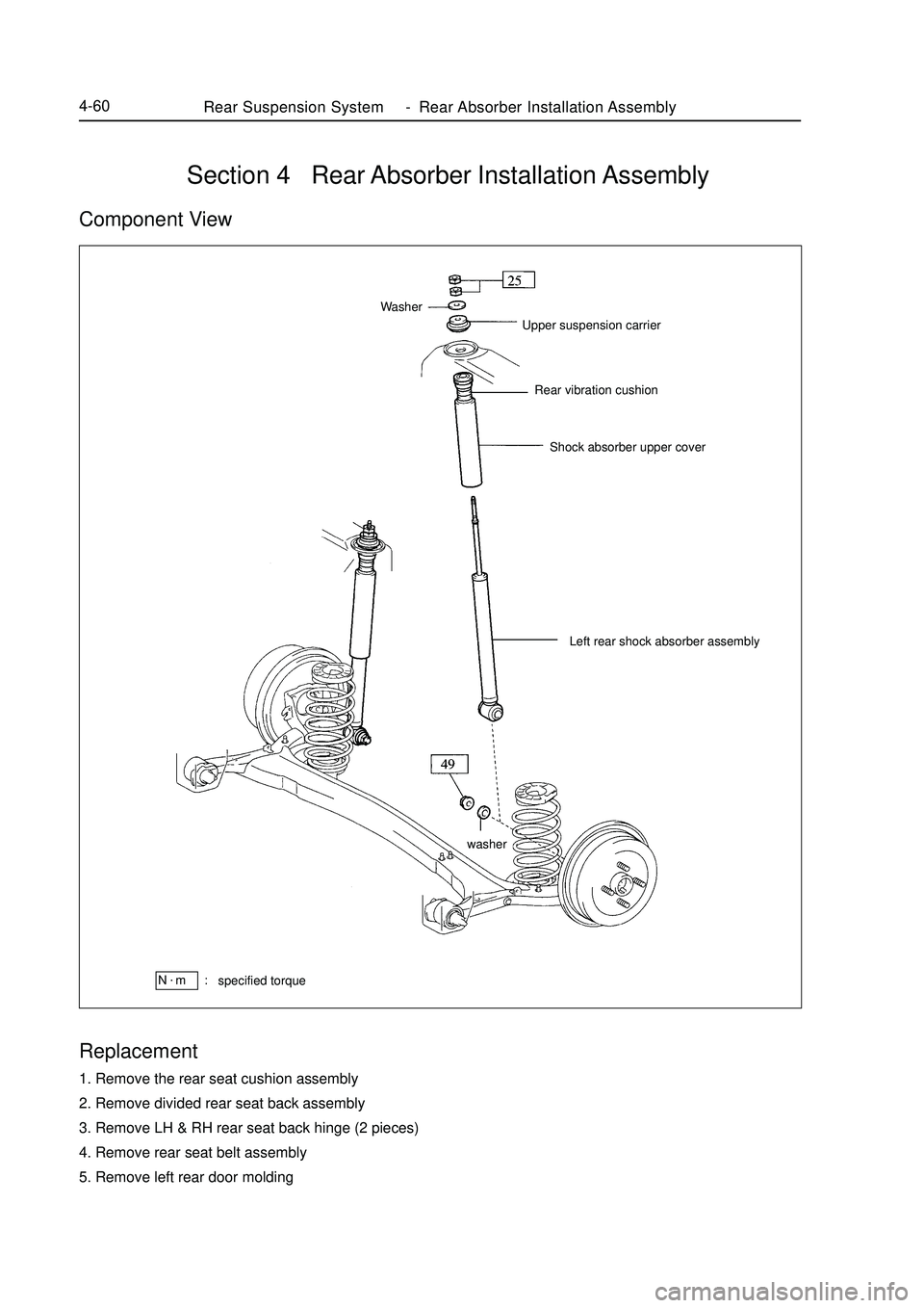
Section 4 Rear Absorber Installation AssemblyComponent ViewReplacement1. Remove the rear seat cushion assembly
2. Remove divided rear seat back assembly
3. Remove LH & RH rear seat back hinge (2 pieces)
4. Remove rear seat belt assembly
5. Remove left rear door moldingUpper suspension carrier
Rear vibration cushion
Shock absorber upper cover WasherLeft rear shock absorber assemblyRear Suspension System-Rear Absorber Installation Assembly4-60specified torqueN.
m :washer
Page 138 of 416

Rear Suspension System-Rear Absorber Installation Assembly4-616. Remove rear left lower pillar interior panel
7. Remove the lower rear shelf interior panel
8. Remove rear left upper pillar interior pane
9. Remove rear right lower pillar interior pane
10. Remove the high brake lamp
11. Remove the rear shelf interior panel
12. Remove rear wheel
13. Remove the rear left shock absorber assembly
(1)Lift the rear axle frame by lifting jack (see right figure)
(2)Remove two nuts by clamping the piston push rod
(3)move the washer and upper suspension bracket
(4) Remove nut, washer and left rear shock absorber assembly
(5) Remove shock absorber upper cover
14. Check rear left shock absorber assembly
Check the abnormal resistance and noise in the operation by
compressing and extending the push rod, replace it if any abnormal.
15.Mount rear left shock absorber assembly
(1) Mount shock absorber upper cover
(2) Mount shock absorber, upper suspension bracket and washer
onto vehicle body
(3) After clamp piston push rod, mount lower nut and let piston
push rod higher 15-18mm than nut (see right figure)
(4) Mount upper nut according lower nut
Torque: 25N.m
(5) Mount shock absorber onto rear axle frame by washer and nut
at lifting jack
Torque: 49N.m
16. Mount rear wheel
Torque: 103N.m
17. Check rear wheel alignment
Page 139 of 416

Section 5 Rear Suspension CrossmemberComponent ViewRear shock absorber subassembly
Upper washer
Left rear helical spring
Lower washer
Rear right support bushingLower washer Right rear helical springUpper washer
Rear suspension
crossmentber
Rear left support bushing
Parking brake cable assembly Load-sensing valve bracket without
ABSRear Suspension System-Rear Suspension Crossmember4-62specified torqueN.
m :Wheel speed sensor wire
Bracket with ABS
Brake hose
Rear brake drum
subassembly
Right rear hub and
bearing subassembly
Rear brake drum
subassembly Rear brake assembly Brake hose
Left rear hub&bearing
subassembly Clamp
Rear stabilizer
bar bushing
Non-reusable parts
Page 140 of 416

Rear Suspension System-Rear Suspension Crossmember4-63Disassemble:1. Remove rear wheel
2. Remove sideslip control sensor wire (with ABS)
3. Remove load-sensing valve bracket (without ABS)
4. Remove proportioning valve and right rear brake tube
5. Remove proportioning valve and left rear brake tube
6. Remove right parking brake cable assembly
7. Remove left parking brake cable assembly
Tips: Remove right parts by using same operations as left
8. Remove rear brake drum subassembly
9. Remove left rear hub and bearing assembly
(1) Remove nuts and right parking brake cable assembly from
rear axle frame
(2) Remove four bolts and left rear hub and bearing assembly
(3) Remove rear brake assembly from rear axle frame
10. Remove rear right hub and bearing assembly
Tips: Remove right parts by using same operations as left
11. Loosen rear axle frame assembly
12. Disassemble rear left shock absorber assembly
13. Disassemble rear right shock absorber assembly
Tips: Remove right parts by using same operations as left
14. Remove rear left helical spring
15. Remove rear right helical spring
Tips: Remove right parts by using same operations as left
16. Remove rear axle assembly
(1) Lift rear axle assembly by lifting axel
(2) Remove two bolts and rear axle frame assembly