ESP GEELY MK 2008 User Guide
[x] Cancel search | Manufacturer: GEELY, Model Year: 2008, Model line: MK, Model: GEELY MK 2008Pages: 416, PDF Size: 25.19 MB
Page 171 of 416

Brake System -Front Brake Disc4-94Component ViewSection 6 Front Brake Disc34Front disc brake pistonSet ring Dust shield Piston oil seal Left front disc
brake cylinder accessory3483088Connector bolt
Washer
Discharge screw
plug capTubeDust shield Front disc brake
cylinder sliding pin
#2 muffle pad
#1 muffle pad
Brake pad
Brake pad#1 muffle pad
#2 muffle pad
Support piece
Front brake pad ISupport piece
Front brake pad IIFront disc brake cylinder
sliding pin88Dust shield
Left cylinder support
Non-reusable parts
Lithium soap base glycol lube
Disc brake lubespecified torqueN.
m :
Page 176 of 416

Section 7 Rear Brake DrumComponent ViewDust shield
Piston
Cup
Spring
Rear bake shoe
Locating spring
Rear brake drum Shoe pad positioning spring cover Front brake shoe
Shoe pad positioning spring cover Pin
BaseboardDust
coverPiston
PinCupLeft parking brake shoe pad postCvlinder
Extension springBrake System -Rear Brake Drum4-99Discharge plug
Discharge plug
Hole plug
Pin plug
C-ringExtension rod
Shoe pad positioning spring Adjustment rod springRear brake automatic
adjustment rodParking brake
inhaul cable
Return spring
Non-reusable parts
Lithium soap base glycol lube
Heat-resistant lubespecified torqueN.
m :
Page 183 of 416
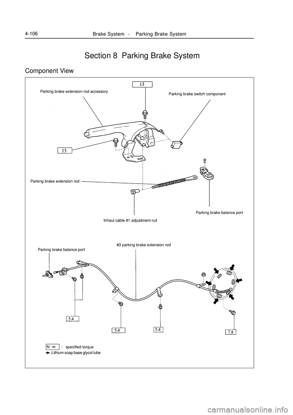
Brake System -Parking Brake System4-106Section 8 Parking Brake SystemComponent View#3 parking brake extension rod
Lithium soap base glycol lubespecified torqueN.
m :Parking brake balance port Parking brake extension rod
Inhaul cable #1 adjustment nutParking brake balance port Parking brake extension rod accessory
Parking brake switch component
Page 184 of 416
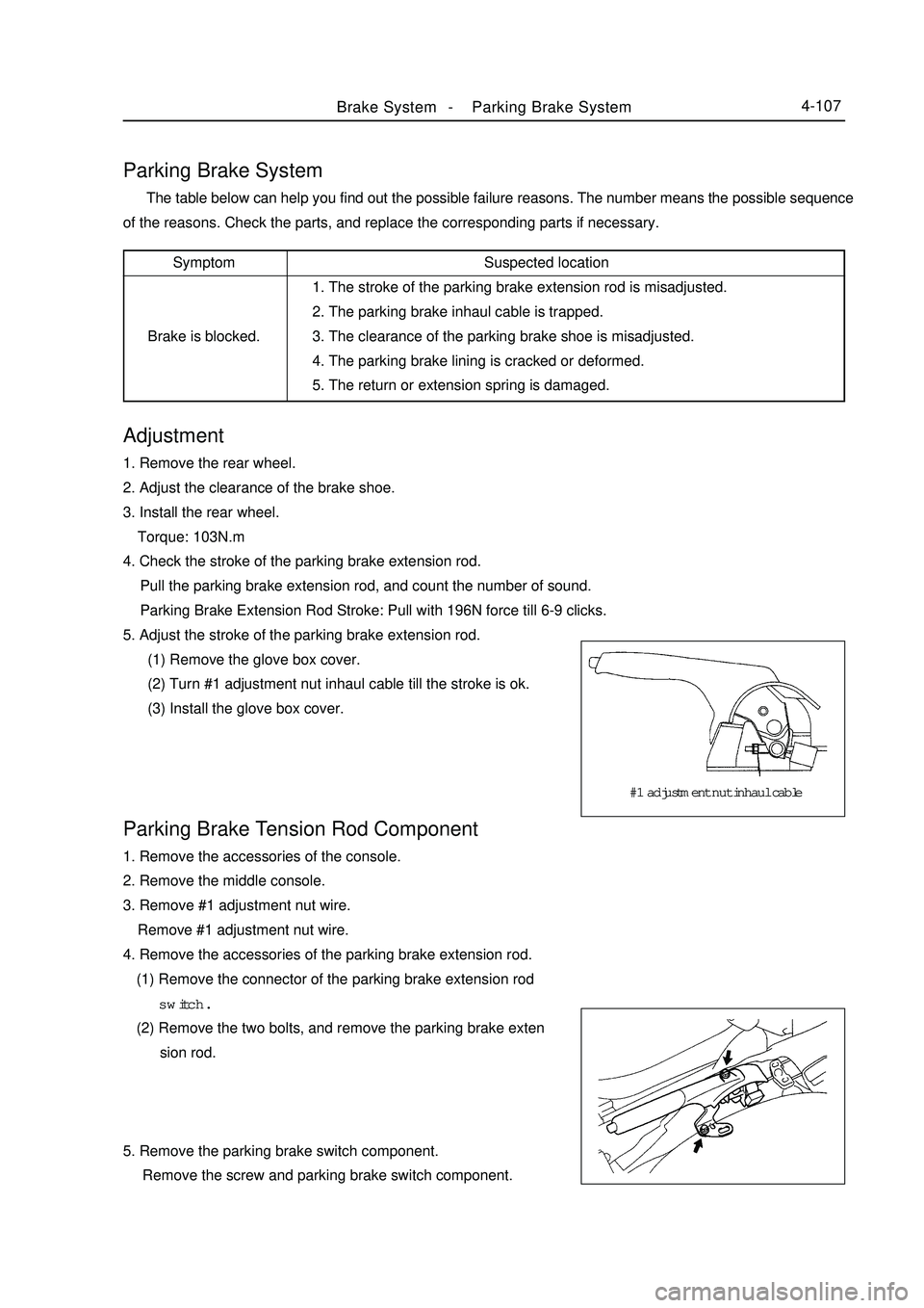
Brake System -Parking Brake System4-107Adjustment1. Remove the rear wheel.
2. Adjust the clearance of the brake shoe.
3. Install the rear wheel.
Torque: 103N.m
4. Check the stroke of the parking brake extension rod.
Pull the parking brake extension rod, and count the number of sound.
Parking Brake Extension Rod Stroke: Pull with 196N force till 6-9 clicks.
5. Adjust the stroke of the parking brake extension rod.
(1) Remove the glove box cover.
(2) Turn #1 adjustment nut inhaul cable till the stroke is ok.
(3) Install the glove box cover.Parking Brake System The table below can help you find out the possible failure reasons. The number means the possible sequence
of the reasons. Check the parts, and replace the corresponding parts if necessary.Parking Brake Tension Rod Component1. Remove the accessories of the console.
2. Remove the middle console.
3. Remove #1 adjustment nut wire.
Remove #1 adjustment nut wire.
4. Remove the accessories of the parking brake extension rod.
(1) Remove the connector of the parking brake extension rod
switch.
(2) Remove the two bolts, and remove the parking brake exten
sion rod.
5. Remove the parking brake switch component.
Remove the screw and parking brake switch component.Suspected location
1. The stroke of the parking brake extension rod is misadjusted.
2. The parking brake inhaul cable is trapped.
3. The clearance of the parking brake shoe is misadjusted.
4. The parking brake lining is cracked or deformed.
5. The return or extension spring is damaged.Symptom
Brake is blocked.#1 adjustment nut inhaul cable
Page 193 of 416
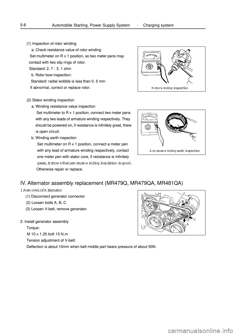
(1) Inspection of rotor winding
a. Check resistance value of rotor winding
Set multimeter on R x 1 position, so two meter pens may
contact with two slip rings of rotor.
Standard: 2. 7 - 3. 1 ohm
b. Rotor bow inspection:
Standard: radial wobble is less than 0. 5 mm
If abnormal, correct or replace rotor.
(2) Stator winding inspection
a. Winding resistance value inspection
Set multimeter to R x 1 position, connect two meter pens
with any two leads of armature winding respectively. They
should be powered on, if resistance is infinitely great, there
is open circuit.
b. Winding earth inspection
Set multimeter on R x 1 position, connect a meter pen
with any lead of armature winding respectively, contact
one meter pen with stator core, if resistance is infinitely
great, it shows that armature winding insulation is good.
Otherwise repair or replace.Automobile Starting, Power Supply System -Charging system5-6IV. Alternator assembly replacement (MR479Q, MR479QA, MR481QA)1.Removel of Alternator
(1) Disconnect generator connector
(2) Loosen bolts A, B, C
(3) Loosen V-belt, remove generator.
2. Install generator assembly
Torque:
M 10 x 1.25 bolt 15 N.m
Tension adjustment of V-belt:
Deflection is about 10mm when belt middle part bears pressure of about 50N.Rotor winding inspection
Armature winding earth inspection
Page 211 of 416
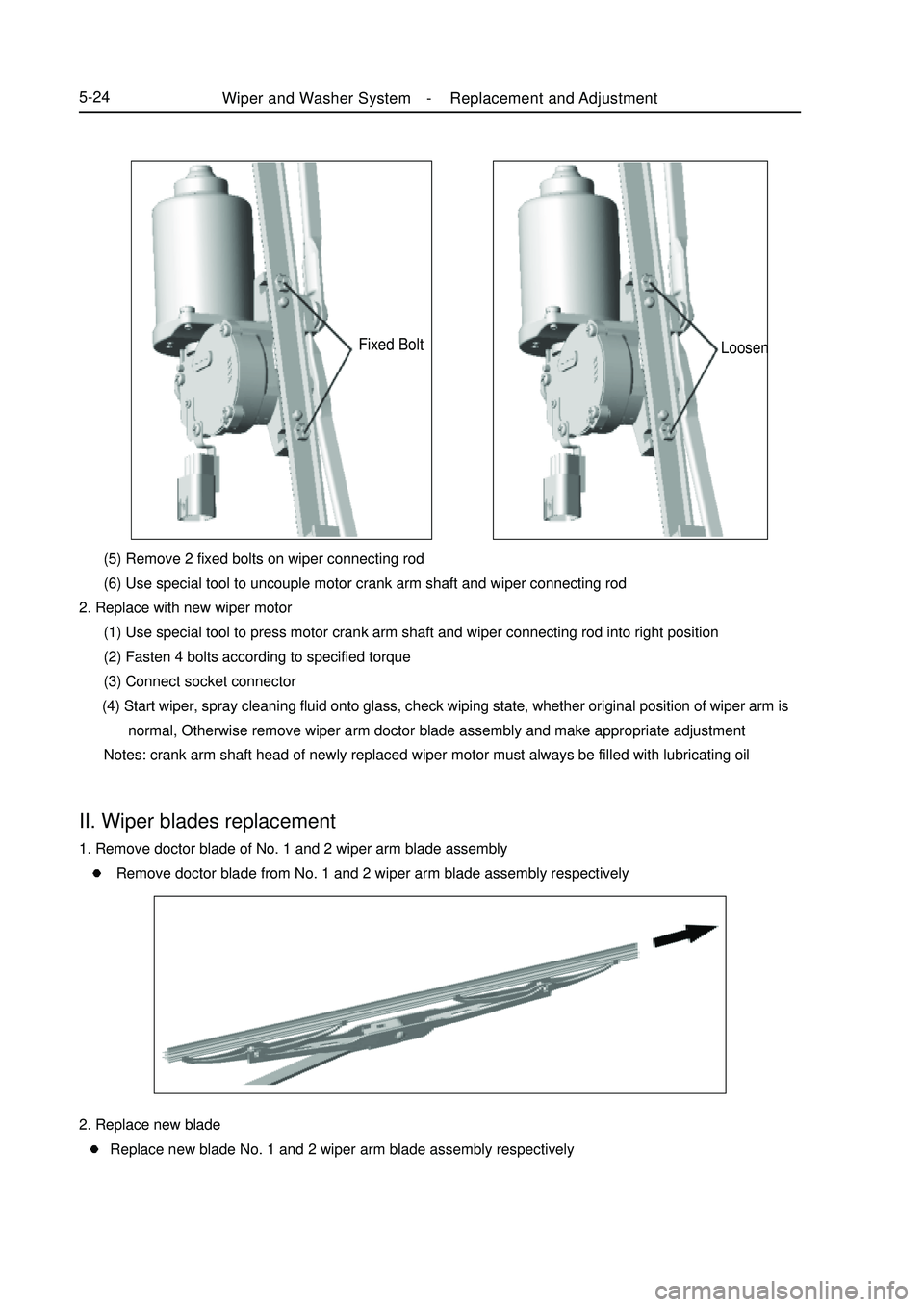
Fixed Bolt (5) Remove 2 fixed bolts on wiper connecting rod
(6) Use special tool to uncouple motor crank arm shaft and wiper connecting rod
2. Replace with new wiper motor
(1) Use special tool to press motor crank arm shaft and wiper connecting rod into right position
(2) Fasten 4 bolts according to specified torque
(3) Connect socket connector
(4) Start wiper, spray cleaning fluid onto glass, check wiping state, whether original position of wiper arm is
normal, Otherwise remove wiper arm doctor blade assembly and make appropriate adjustment
Notes: crank arm shaft head of newly replaced wiper motor must always be filled with lubricating oilII. Wiper blades replacement1. Remove doctor blade of No. 1 and 2 wiper arm blade assembly
Remove doctor blade from No. 1 and 2 wiper arm blade assembly respectivelyLoosenWiper and Washer System -Replacement and Adjustment5-242. Replace new blade
Replace new blade No. 1 and 2 wiper arm blade assembly respectively
Page 225 of 416

Wave band LF MF HF VHF
Radio wave AM FM
Modulation Amplitude modulation Frequency modulationFrequency 30KHZ 300KHZ 3MHZ 30MHZ 300MHZ
2. Area coverage
Scope of AM and FM broadcasting coverage area differs greatly.
Sometimes although AM broadcast may be received clearly, FM
binaural broadcasting cannot be received. Not only listening zone of
FM binaural broadcasting is small, but also static noise or other
cacophony (noise) tends to occur.
3. Receiving problem
Notes:
Besides static noise problem, there is also interference, multiplex
and attenuation. These problems are not caused by electric cacophony,
but the problem of radio wave itself.
(1) Interference
Besides static noise problem, AM broadcast tends to receive
other types of noise, especially at night. This is because ionosphere
reflects AM radio wave at night, these interference electric waves
interfere with signals from the same signal source while entering into
vehicle antenna directly, this kind of noise is called "interference".
(2) Multiplex
Noise caused by radio wave reflected from barrier is called
"multiplex". When radio signal emitted by broadcast antenna is
reflected by high buildings or high mountains, and disturbs directly
received other signals, multiplex phenomenon occurs.
(3) Attenuation
Since its frequency is higher than AM, FM wave is more easily
reflected by high buildings or high mountains. Therefore, FM signal
often disappears gradually, or when vehicle is blocked by barrier, it
cannot receive any signal, such phenomenon is called "attenuation".Audio System -Audio System Description5-38Chapter 5 Audio SystemSection 1 Audio System DescriptionDescription:
1. Radio wave band
Wave bands used in radiobroadcast are as follows:
LF: low frequency MF: medium frequency HF: high frequency VHF: very high frequencyFM (stereo)
FM (non-stereo)
AMInterference
IonosphereMultiplexAttenuation
Page 231 of 416

(1) Check LCD Illumination
a. Turn the ignition switch to ACC
b. Turn on radio assembly
c. Turn on the position light
Standard: The LCD indicator of the radio assembly goes on
Abnormal: go to step (7)
Normal: go to the next step
(2) Control volume and adjust the volume balance
Adjust the volume and its balance of the radio assembly to find out the inaudible speaker.
If all speakers are mute, check and replace the radio assembly
If individual speaker is mute, then respectively check and replace the inaudible speaker.
(3) Tweeter assembly inspection
a. Disconnect the speaker connector
b. Check the resistance
Notice:
Do not remove the speaker during inspection.
Standard Value: 4 ohm
Abnormal: Replace tweeter speaker assembly
Normal: Check wire harness and connector
(4) Check front speaker assembly
a. Disconnect speaker connector
b. Check resistance
Standard Value: 4 ohm
Abnormal: Replace front speaker assembly
Normal: Check wire harness and connector
(5) Check rear speaker assembly
a. Disconnect speaker connector
b. Check resistance
Standard Value: 4 ohm
Abnormal: Replace rear speaker assembly
Normal: Check wire harness and connector
(6) Check wire harness and connector
Abnormal Repair or replace wire harness and connector
Normal Check and replace radio assembly
(7) Check and replace radio assembly (+B, ACC, GND)
a. Check the continuity between terminals under each operating condition as shown in the table below.
Standard:Audio System -Audio System Inspection5-44Tester connection Condition Standard Status
GND Normal ON
Page 262 of 416
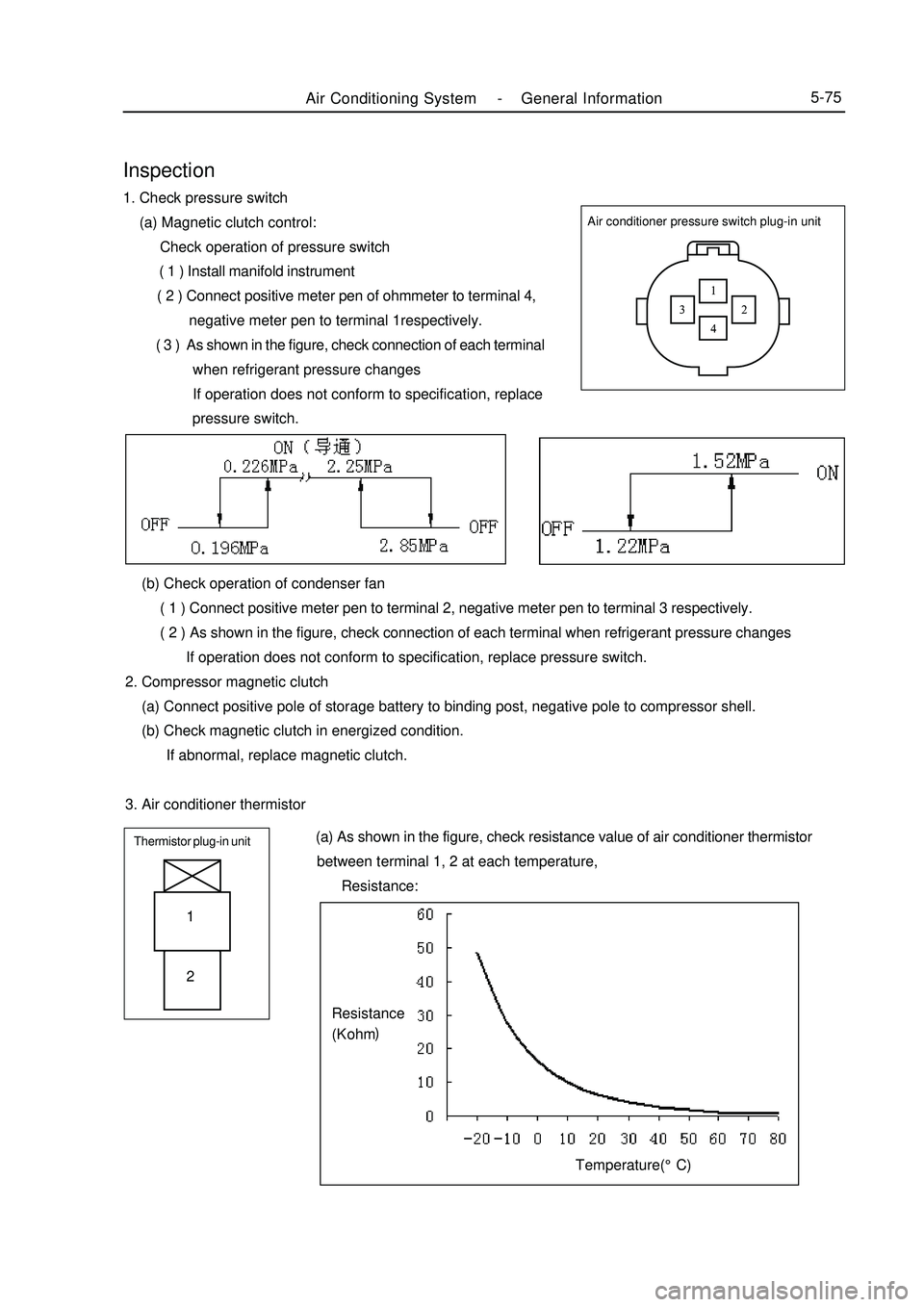
Air Conditioning System -General Information5-75Air conditioner pressure switch plug-in unitInspection1. Check pressure switch
(a) Magnetic clutch control:
Check operation of pressure switch
( 1 ) Install manifold instrument
( 2 ) Connect positive meter pen of ohmmeter to terminal 4,
negative meter pen to terminal 1respectively.
( 3 ) As shown in the figure, check connection of each terminal
when refrigerant pressure changes
If operation does not conform to specification, replace
pressure switch.
(b) Check operation of condenser fan
( 1 ) Connect positive meter pen to terminal 2, negative meter pen to terminal 3 respectively.
( 2 ) As shown in the figure, check connection of each terminal when refrigerant pressure changes
If operation does not conform to specification, replace pressure switch.
2. Compressor magnetic clutch
(a) Connect positive pole of storage battery to binding post, negative pole to compressor shell.
(b) Check magnetic clutch in energized condition.
If abnormal, replace magnetic clutch.
3. Air conditioner thermistorThermistor plug-in unit (a) As shown in the figure, check resistance value of air conditioner thermistor
between terminal 1, 2 at each temperature,
Resistance:1
2Temperature(°C)Resistance
(K ohm)
Page 287 of 416
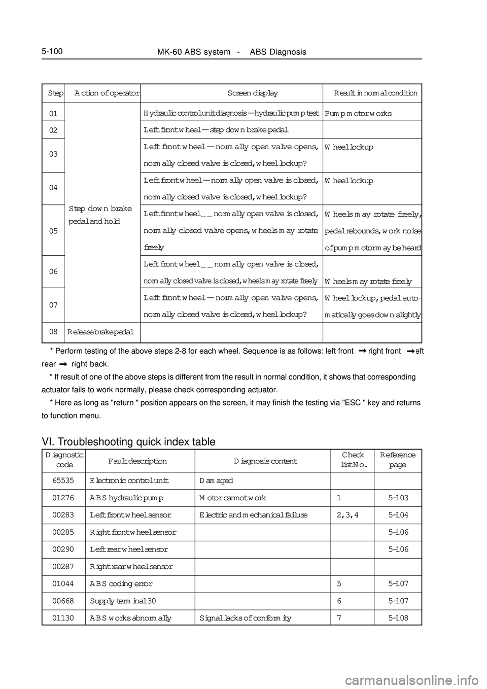
Step Action of operator Screen displayResult in normal conditionPump motor works
Wheel lockup
Wheel lockup
Wheels may rotate freely,
pedal rebounds, work noise
of pump motor may be heard
Wheels may rotate freely
Wheel lockup, pedal auto-
matically goes down slightlyHydraulic control unit diagnosis -- hydraulic pump testLeft front wheel -- step down brake pedal
Left front wheel -- normally open valve opens,
normally closed valve is closed, wheel lockup?
Left front wheel -- normally open valve is closed,
normally closed valve is closed, wheel lockup?
Left front wheel _ _ normally open valve is closed,
normally closed valve opens, wheels may rotate
freelyLeft front wheel _ _ normally open valve is closed,
normally closed valve is closed, wheels may rotate freelyLeft front wheel -- normally open valve opens,
normally closed valve is closed, wheel lockup?
Release brake pedal 01
02
03
04
05
06
07
08Step down brake
pedal and hold
* Perform testing of the above steps 2-8 for each wheel. Sequence is as follows: left front right front left
rear right back.
* If result of one of the above steps is different from the result in normal condition, it shows that corresponding
actuator fails to work normally, please check corresponding actuator.
* Here as long as "return " position appears on the screen, it may finish the testing via "ESC " key and returns
to function menu.VI. Troubleshooting quick index tableMK-60 ABS system - ABS Diagnosis5-100Diagnostic
codeFault description Diagnosis contentCheck
list No.Reference
page
65535
01276
00283
00285
00290
00287
01044
00668
01130Electronic control unit
ABS hydraulic pump
Left front wheel sensor
Right front wheel sensor
Left rear wheel sensor
Right rear wheel sensor
ABS coding error
Supply terminal 30
ABS works abnormallyDamaged
Motor cannot work
Electric and mechanical failure
Signal lacks of conformity5-103
5-104
5-106
5-106
5-107
5-107
5-108 1
2, 3, 4
5
6
7