Sensor oil GEELY MK 2008 User Guide
[x] Cancel search | Manufacturer: GEELY, Model Year: 2008, Model line: MK, Model: GEELY MK 2008Pages: 416, PDF Size: 25.19 MB
Page 98 of 416

Overhaul1. Drain manual transmission oil (M/T transmission)
Torque: 39N.m
2. Drain automatic transmission oil (A/T transmission)
Torque: 25N.m
3. Remove front wheel
4. Remove engine bottom left shield (M/T transaxle)
5. Remove engine bottom right shield (M/T transaxle)
6. Remove engine bottom shield assembly (A/T transaxle)
7. Remove front wheel hub left bolt
(1) Using a hammer and a drive shaft nut chisel, unstake the
staked part of the left wheel hub nut.
(2) While applying the brake pedal, remove the left wheel hub
nut.
Notice: the staked part of the nut should be fully unstaked,
otherwise it may damage the thread of the drive shaft.
8. Remove left front vehicle speed sensor (with ABS)
(1) Remove the bolt and clip, remove vehicle speed sensor and
brake hose from left front shock absorber assembly.
(2) Remove the bolt, separate the left front vehicle speed sensor
from steering knuckle.
9. Remove front stabilizer bar
(1) Use a 10mm wrench to hold the bolt, remove the nut
(2) Remove two collars, No.1 and No.2 gaskets, remove front
stabilizer barPropeller Shaft/DriveshaftFront Driveshaft4-21 -
Page 99 of 416

10. Separate left lower swing arm assembly
(1) Remove cotter pin and nut
(2) On steering knuckle, remove the left lower swing arm
assembly with ball joint puller.
11. Separate steering gear with tie rod assembly
(1) Remove cotter pin and nut
(2) On steering knuckle, remove the steering gear with tie rod
assembly with ball joint puller.Propeller Shaft/DriveshaftFront Driveshaft4-2212. Separate LF steering knuckle assembly
Using a plastic hamper, separate left front drive shaft assembly from left front steering knuckle assembly
Notice:
Do not damage the boot.
With ABS:
Be careful not to damage the vehicle speed sensor rotor.
13. Remove left constant velocity drive shaft assembly
Using a differential side gear shaft remover, remove the left
constant velocity drive shaft assembly.
Notice:
Do not damage the boot and oil seal.
Be careful not to drop the drive shaft assembly.
14. Remove right constant velocity drive shaft assembly
Using a brass bar and a hammer, remove the right constant
velocity drive shaft assembly.
Notice:
Do not damage the boot and oil seal.
Be careful not to drop the drive shaft assembly. -
Page 105 of 416

Propeller Shaft/DriveshaftFront Driveshaft4-28 Hint:
Please refer to the following table for dimension (A).LH mm
528.3±5.0
527.0±5.0RH mm
859.3±5.0
860.0±5.0 M/T manual transmission
A/T automatic transmission38. Install left constant velocity drive shaft assembly
(1) M/T
Coat the spline of the tripod joint assembly with gear oil.
(2) A/T
Coat the spline of the tripod joint assembly with ATF
(Automatic Transmission Fluid).
(3) Align the spline, use a brass bar and hammer to install the left
drive shaft assembly.
Notice:
Face the retainer open end downward.
Be careful not to damage the boot and oil seal.
Hint:
You can find out whether the tripod joint shaft contact the pinion shaft by rotating the shaft assembly, listening
to the sound and feeling.
39. Install right constant velocity drive shaft assembly
Hint:
The installation of the right side is the same as that of the left side.
Notice:
Install the retainer with its open end facing downward.
Be careful not to damage the boot and oil seal.
40. Install left steering knuckle assembly
Install the left constant velocity drive shaft assembly on the left steering knuckle assembly.
Notice:
Be careful not to damage the outboard joint boot.
With ABS:
Be careful not to damage the vehicle speed sensor rotor.
41. Install left steering gear with tie rod assembly
(1) Install the steering gear with tie rod assembly on the steering knuckle assembly with nuts.
Torque: 33N.m
(2) Install the new cotter pins.
Notice:
If the pin holes are not aligned, further tighten the nut by 60°.
42. Install left lower swing arm assembly
(1) Install the left lower swing arm assembly on the steering knuckle assembly with nuts.
Torque: 98N.m -
Page 106 of 416

Propeller Shaft/DriveshaftFront Driveshaft4-29 (2) Install the new cotter pins.
Notice:
If the pin holes are not aligned, further tighten the nut by 60°.
43. Install front stabilizer bar
(1) As shown in the illustration, install the stabilizer bar with two
No.1 collars and two gaskets and nuts.
Notice:
Make sure the gaskets and collars are correctly installed.
(2) Tighten the nut with a 10mm wrench.
Torque: 18N.m
44. Install left front vehicle speed sensor (with ABS)
(1) Install the left front vehicle speed sensor and brake hose on the
front shock absorber with bolts and clps.
Torque: 29N.m
(2) Install the vehicle speed sensor on the steering knuckle with
bolts.
Torque: 8.0N.m
Notice:
Be careful not to damage the wheel speed sensor.
Keep the vehicle speed sensor clean.
When installing the sensor,do not twist the sensor wire harness.
45. Install left steering knuckle wheel hub nut
(1) Install new left steering knuckle hub nuts
Torque: 216N.m
(2) Using a chisel and hammer, stake the hub locking nut.
46. Install engine bottom left shield
47. Install engine bottom right shield
48. Install engine bottom shield assembly
49. Install front wheel
Torque: 103 N.m
50. Add oil into manual transmission
51. Check and adjust the manual transmission fluid
52. Refill automatic transmission fluid
53. Check and adjust the automatic transmission fluid
54. Check and adjust front wheel alignment
55. Check ABS vehicle speed signal (with ABS) -
Page 110 of 416

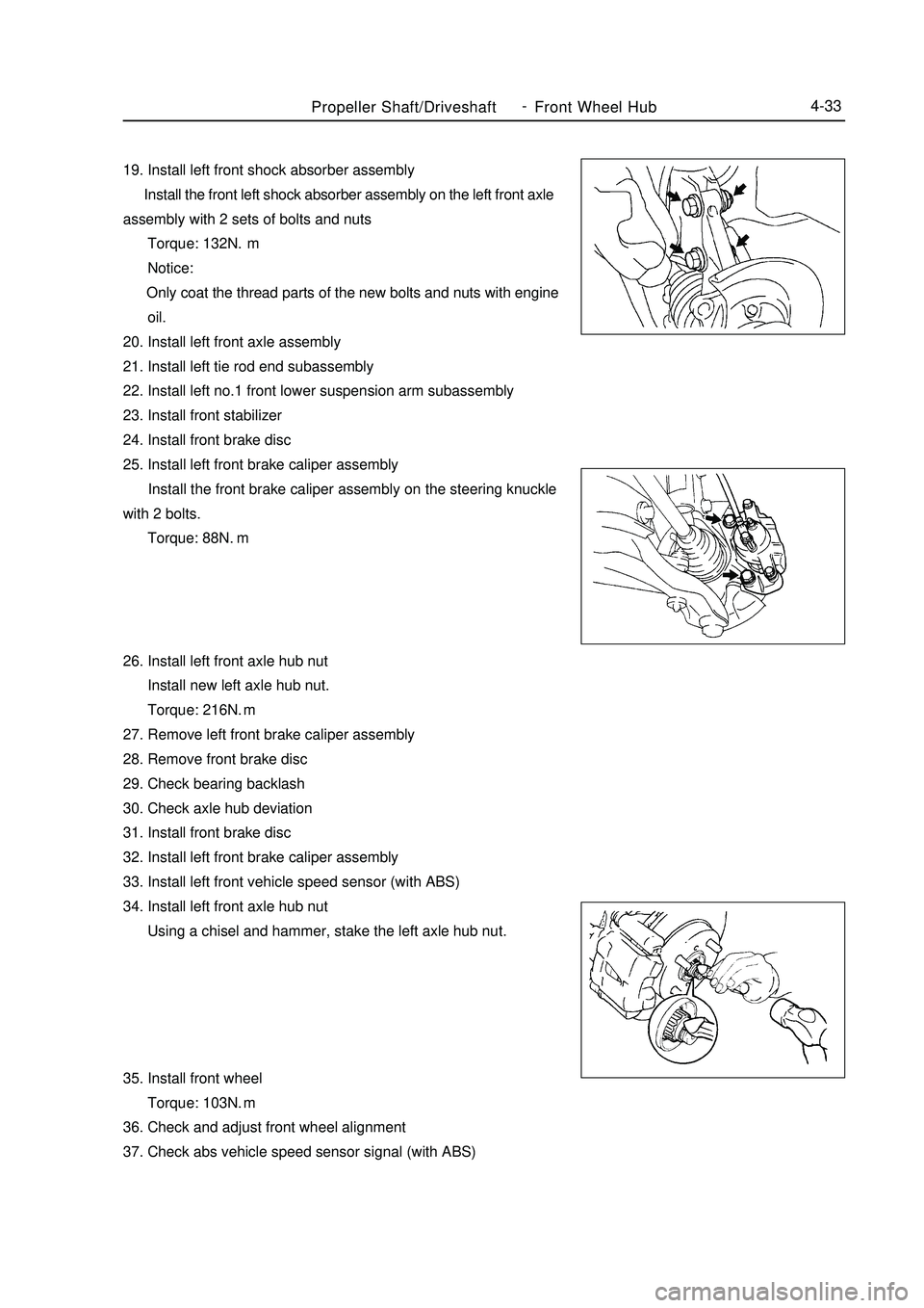
Propeller Shaft/DriveshaftFront Wheel Hub4-3319. Install left front shock absorber assembly
Install the front left shock absorber assembly on the left front axle
assembly with 2 sets of bolts and nuts
Torque: 132N.m
Notice:
Only coat the thread parts of the new bolts and nuts with engine
oil.
20. Install left front axle assembly
21. Install left tie rod end subassembly
22. Install left no.1 front lower suspension arm subassembly
23. Install front stabilizer
24. Install front brake disc
25. Install left front brake caliper assembly
Install the front brake caliper assembly on the steering knuckle
with 2 bolts.
Torque: 88N.
m
26. Install left front axle hub nut
Install new left axle hub nut.
Torque: 216N.m
27. Remove left front brake caliper assembly
28. Remove front brake disc
29. Check bearing backlash
30. Check axle hub deviation
31. Install front brake disc
32. Install left front brake caliper assembly
33. Install left front vehicle speed sensor (with ABS)
34. Install left front axle hub nut
Using a chisel and hammer, stake the left axle hub nut.
35. Install front wheel
Torque: 103N.m
36. Check and adjust front wheel alignment
37. Check abs vehicle speed sensor signal (with ABS) -
Page 134 of 416

Section 3 LH/RH Rear Suspension Coil SpringReplacement1. Remove rear wheel
2. Remove the wire of the wheel speed sensor(with ABS)
(1) Remove the connector of wheel speed sensor.
(2) Remove bolts and wheel speed sensor from rear axle
frame.
Notes:
Remove the right sensor wire by using same process as left.
3. Remove the load-sensing valve bracket (without ABS)
Remove two nuts and load-sensing valve bracket from the axle
bracket
4. Remove the proportioning valve and rear right brake tube
(1) Remove the proportioning valve and rear right brake tube by
the special tool
(2) Remove the clips
Notes: Don't reuse the clips
5. Remove the proportioning valve and rear left brake tube
Notes: use the same operations of the proportioning valve and
rear right brake tube to remove #3 rear brake tube.
6. Remove right parking brake cable assembly
Remove nuts and right parking brake cable assembly
assembly from rear axle frame
7. Remove left parking brake cable assembly
8. Loose the rear axle assembly
Loose two 2 boltsRear Suspension System-LH/RH Rear Suspension Coil Spring4-57
Page 136 of 416

Rear Suspension System-LH/RH Rear Suspension Coil Spring4-5918. Mount rear right brake tube
Tips:
Mount the right assembly by using same operations as left.
19. Mount sideslip control sensor wire (with ABS)
(1) Tighten sideslip control sensor wire by bolts
Torque: 8.0 N.m
(2) Mount sideslip control sensor wire
Attention: Mount the right wire by using same operations as left.
20. Mount load-sensing valve bracket (without ABS)
Mount load-sensing valve bracket by two buts
21. Sufficiently tighten the rear axle frame assembly
(1) Stabilize the shock absorber assembly
Use the lifting jack and add 90Kg force on rear luggage
carrier if bolts can not be tightened at this point.
(2) Sufficiently tighten bolts
Torque: 82 N.m
22. Sufficiently tighten the left rear shock absorber assembly
Sufficiently tighten nuts
Torque: 49 N.m
23. Sufficiently tighten the right rear shock absorber assembly
Tips: Mount the right rear shock absorber by using same opera-
tions as left.
24. Release the air in the brake hose
25. Mount the rear wheel
Torque: 103 N.m
26. Check rear the wheel alignment
27. Check the wheel speed sensor signal of ABS( with ABS)
Page 196 of 416

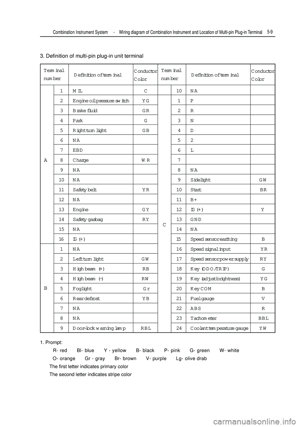
3. Definition of multi-pin plug-in unit terminal
1. Prompt:
R- red Bl- blue Y - yellow B- black P- pink G- green W- white
O- orange Gr - gray Br- brown V- purple Lg- olive drab
The first letter indicates primary color
The second letter indicates stripe colorTerminal
number1 MIL C 10 NA
2 Engine oil pressure switch YG 1 P
3 Brake fluid GR 2 R
4 Park G 3 N
5 Right turn light GB 4 D
6NA 52
7 EBD 6 L
8 Charge WR 7
9NA 8NA
10 NA 9 Sidelight GW
11 Safety belt YR 10 Start BR
12 NA 11 B+
13 Engine GY 12IG ( + ) Y
14 Safety gasbag RY 13 GND
15 NA 14 NA
16 IG ( + ) 15Speed sensor earthing B
1 NA 16 Speed signal input YR
2 Left turn light GW 17 Speed sensor power supply RY
3 High beam (+) RB 18 Key (ODO/TRIP) G
4 High beam (-) RW 19 Key (adjust brightness) YG
5 Foglight Gr 20 Key COM B
6 Rear defrost YB 21 Fuel gauge V
7 NA 22 ABS R
8 NA 23 Tachometer BBL
9 Door-lock warning lamp RBL 24 Coolant temperature gauge YWA
BCCombination Instrument System -Wiring diagram of Combination Instrument and Location of Multi-pin Plug-in Terminal5-9Definition of terminalConductor
ColorTerminal
numberDefinition of terminalConductor
Color
Page 206 of 416

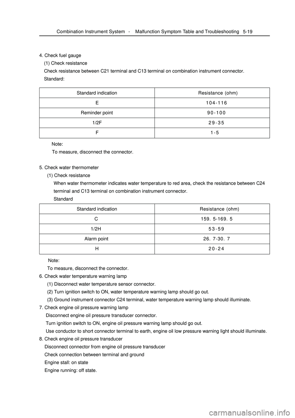
Note:
To measure, disconnect the connector.
5. Check water thermometer
(1) Check resistance
When water thermometer indicates water temperature to red area, check the resistance between C24
terminal and C13 terminal on combination instrument connector.
Standard 4. Check fuel gauge
(1) Check resistance
Check resistance between C21 terminal and C13 terminal on combination instrument connector.
Standard:5-19Standard indication
E
Reminder point
1/2F
FResistance (ohm)
104-116
90-100
29-35
1-5
Standard indication
C
1/2H
Alarm point
HResistance (ohm)
159. 5-169. 5
53-59
26. 7-30. 7
20-24
Note:
To measure, disconnect the connector.
6. Check water temperature warning lamp
(1) Disconnect water temperature sensor connector.
(2) Turn ignition switch to ON, water temperature warning lamp should go out.
(3) Ground instrument connector C24 terminal, water temperature warning lamp should illuminate.
7. Check engine oil pressure warning lamp
Disconnect engine oil pressure transducer connector.
Turn ignition switch to ON, engine oil pressure warning lamp should go out.
Use conductor to short connector terminal to earth, engine oil low pressure warning light should illuminate.
8. Check engine oil pressure transducer
Disconnect connector from engine oil pressure transducer
Check connection between terminal and ground
Engine stall: on state
Engine running: off state.Combination Instrument System -Malfunction Symptom Table and Troubleshooting
Page 291 of 416

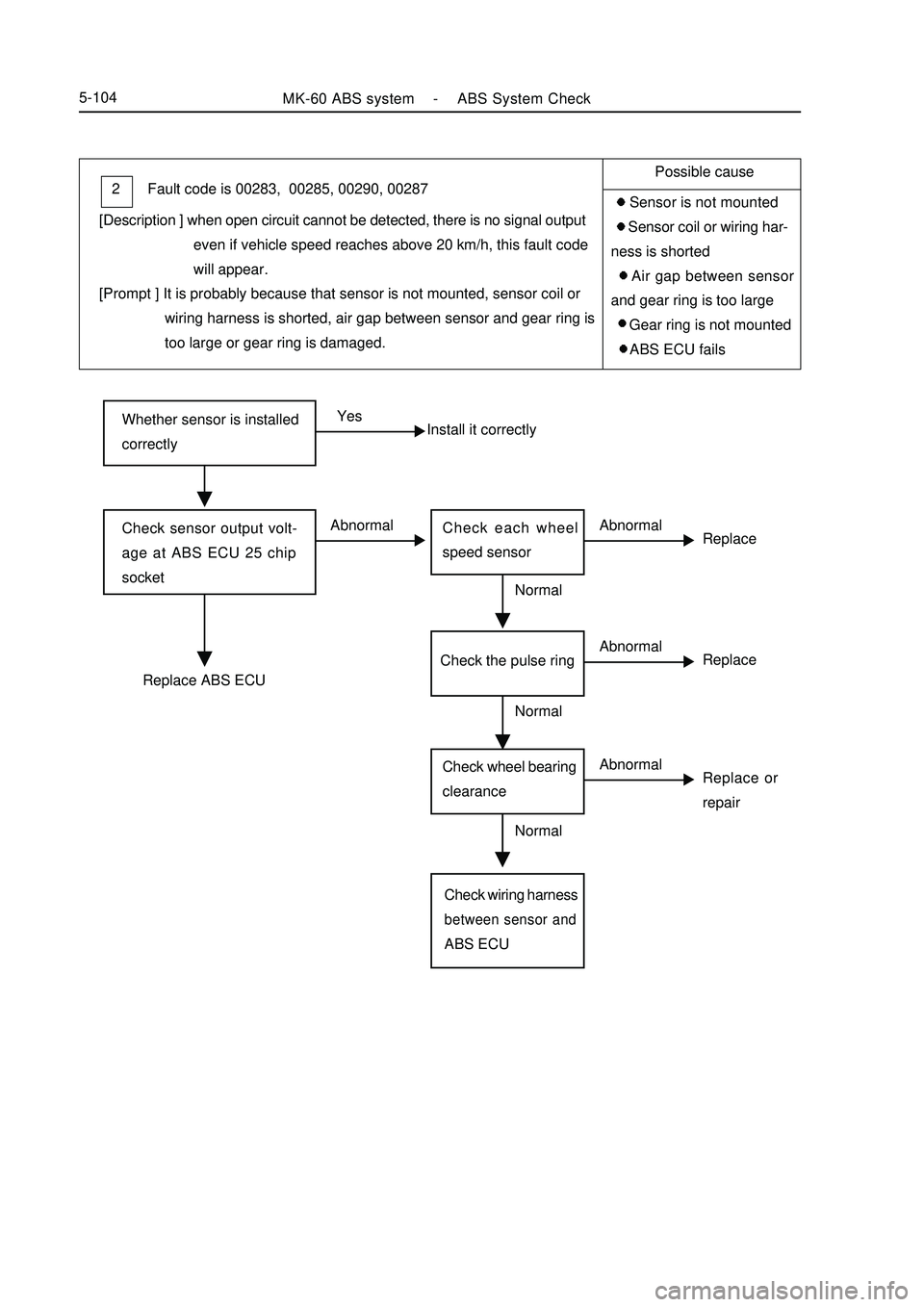
Whether sensor is installed
correctlyYes
Install it correctlyCheck sensor output volt-
age at ABS ECU 25 chip
socketAbnormal
ReplaceCheck each wheel
speed sensorAbnormalReplace ABS ECUNormal
Replace or
repairCheck wheel bearing
clearanceAbnormalCheck wiring harnessbetween sensor andABS ECUNormalMK-60 ABS system -ABS System Check5-104Fault code is 00283, 00285, 00290, 00287 2
[Description ] when open circuit cannot be detected, there is no signal output
even if vehicle speed reaches above 20 km/h, this fault code
will appear.
[Prompt ] It is probably because that sensor is not mounted, sensor coil or
wiring harness is shorted, air gap between sensor and gear ring is
too large or gear ring is damaged.Possible cause
Sensor is not mounted
Sensor coil or wiring har-
ness is shorted
Air gap between sensor
and gear ring is too large
Gear ring is not mounted
ABS ECU fails
ReplaceCheck the pulse ringAbnormalNormal