brake light GEELY MK 2008 User Guide
[x] Cancel search | Manufacturer: GEELY, Model Year: 2008, Model line: MK, Model: GEELY MK 2008Pages: 416, PDF Size: 25.19 MB
Page 160 of 416
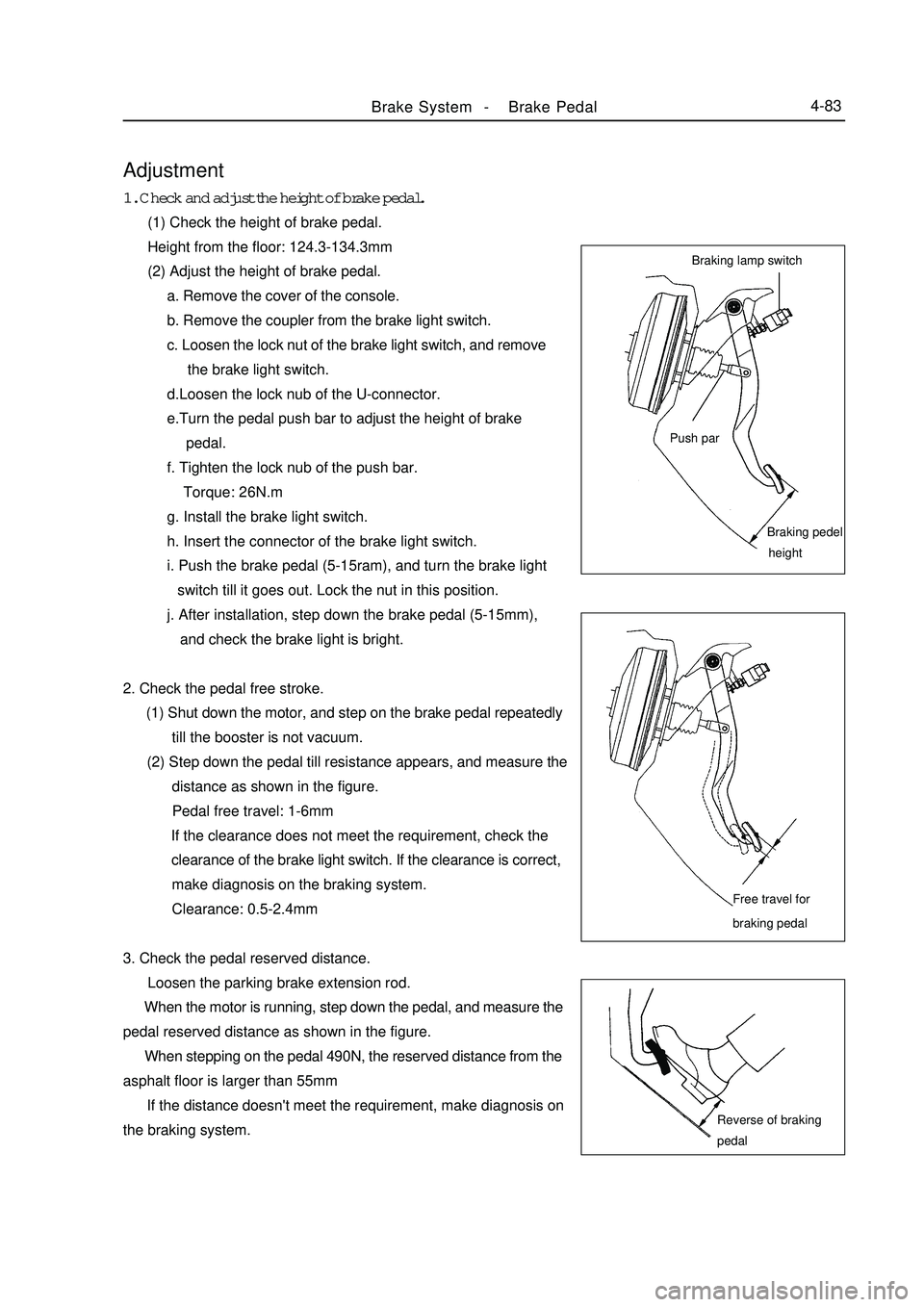
Adjustment1. Check and adjust the height of brake pedal.
(1) Check the height of brake pedal.
Height from the floor: 124.3-134.3mm
(2) Adjust the height of brake pedal.
a. Remove the cover of the console.
b. Remove the coupler from the brake light switch.
c. Loosen the lock nut of the brake light switch, and remove
the brake light switch.
d.Loosen the lock nub of the U-connector.
e.Turn the pedal push bar to adjust the height of brake
pedal.
f. Tighten the lock nub of the push bar.
Torque: 26N.m
g. Install the brake light switch.
h. Insert the connector of the brake light switch.
i. Push the brake pedal (5-15ram), and turn the brake light
switch till it goes out. Lock the nut in this position.
j. After installation, step down the brake pedal (5-15mm),
and check the brake light is bright.
2. Check the pedal free stroke.
(1) Shut down the motor, and step on the brake pedal repeatedly
till the booster is not vacuum.
(2) Step down the pedal till resistance appears, and measure the
distance as shown in the figure.
Pedal free travel: 1-6mm
If the clearance does not meet the requirement, check the
clearance of the brake light switch. If the clearance is correct,
make diagnosis on the braking system.
Clearance: 0.5-2.4mm
3. Check the pedal reserved distance.
Loosen the parking brake extension rod.
When the motor is running, step down the pedal, and measure the
pedal reserved distance as shown in the figure.
When stepping on the pedal 490N, the reserved distance from the
asphalt floor is larger than 55mm
If the distance doesn't meet the requirement, make diagnosis on
the braking system.Brake System -Brake Pedal4-83Braking lamp switch
Push parBraking pedel
heightFree travel for
braking pedalReverse of braking
pedal
Page 161 of 416
1
2
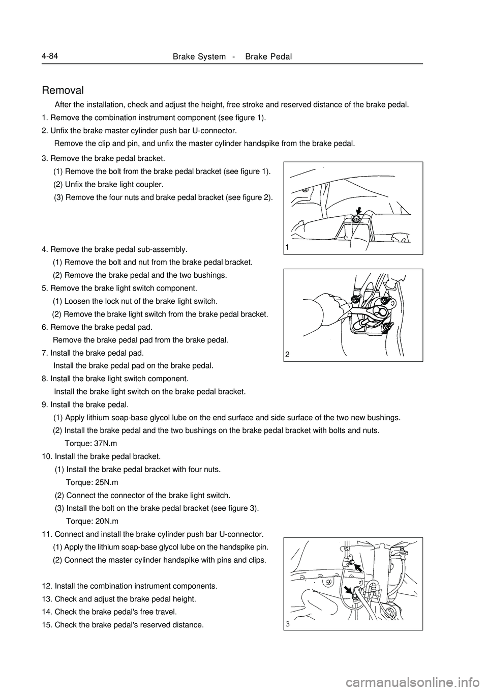
3Brake System -Brake Pedal4-84Removal After the installation, check and adjust the height, free stroke and reserved distance of the brake pedal.
1. Remove the combination instrument component (see figure 1).
2. Unfix the brake master cylinder push bar U-connector.
Remove the clip and pin, and unfix the master cylinder handspike from the brake pedal.
3. Remove the brake pedal bracket.
(1) Remove the bolt from the brake pedal bracket (see figure 1).
(2) Unfix the brake light coupler.
(3) Remove the four nuts and brake pedal bracket (see figure 2).
4. Remove the brake pedal sub-assembly.
(1) Remove the bolt and nut from the brake pedal bracket.
(2) Remove the brake pedal and the two bushings.
5. Remove the brake light switch component.
(1) Loosen the lock nut of the brake light switch.
(2) Remove the brake light switch from the brake pedal bracket.
6. Remove the brake pedal pad.
Remove the brake pedal pad from the brake pedal.
7. Install the brake pedal pad.
Install the brake pedal pad on the brake pedal.
8. Install the brake light switch component.
Install the brake light switch on the brake pedal bracket.
9. Install the brake pedal.
(1) Apply lithium soap-base glycol lube on the end surface and side surface of the two new bushings.
(2) Install the brake pedal and the two bushings on the brake pedal bracket with bolts and nuts.
Torque: 37N.m
10. Install the brake pedal bracket.
(1) Install the brake pedal bracket with four nuts.
Torque: 25N.m
(2) Connect the connector of the brake light switch.
(3) Install the bolt on the brake pedal bracket (see figure 3).
Torque: 20N.m
11. Connect and install the brake cylinder push bar U-connector.
(1) Apply the lithium soap-base glycol lube on the handspike pin.
(2) Connect the master cylinder handspike with pins and clips.
12. Install the combination instrument components.
13. Check and adjust the brake pedal height.
14. Check the brake pedal's free travel.
15. Check the brake pedal's reserved distance.
Page 164 of 416

Repair1. Discharge the brake fluid.
Note: Never spray the brake fluid on the paint surface, otherwise
wash it immediately.
2. Remove the brake master cylinder.
(1) Pull out the connector of the level alarm light switch.
(2) Slide the clip, and pull out #1 clutch storage tank pipe (manual
transaxle).
(3) Remove the two brake pipes from the brake master cylinder
with special tool.(with ABS)
(4) Remove the three brake pipes from the brake master cylinder
accessory with special tool. (without ABS)
(5) Remove the two lock nuts, and pull out the brake master
pump.
3. Remove the storage tank.
(1) Put the brake master cylinder on the bench clamp.
(2) Remove the pin from the brake master cylinder body with
punch and hammer.
(3) Pull out the Brake fluid reservoir.
(4) Remove the cover and strainer from the storage tank.
(5) Remove the storage tank and the two hole connectors.
4. Remove the brake master cylinder.
(1) Put the brake master cylinder on the bench clamp.
(2) Remove the O-ring.
(3) Push the piston with hand, and remove the snap ring with
snap ring pliers.Brake System -Brake Master Cylinder Assembly4-87With ABS:
Without ABS
Page 196 of 416
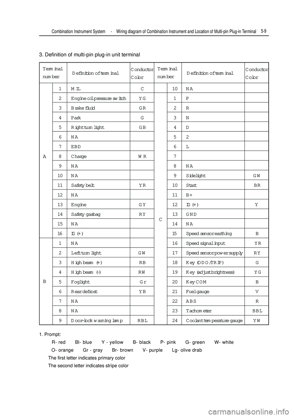
3. Definition of multi-pin plug-in unit terminal
1. Prompt:
R- red Bl- blue Y - yellow B- black P- pink G- green W- white
O- orange Gr - gray Br- brown V- purple Lg- olive drab
The first letter indicates primary color
The second letter indicates stripe colorTerminal
number1 MIL C 10 NA
2 Engine oil pressure switch YG 1 P
3 Brake fluid GR 2 R
4 Park G 3 N
5 Right turn light GB 4 D
6NA 52
7 EBD 6 L
8 Charge WR 7
9NA 8NA
10 NA 9 Sidelight GW
11 Safety belt YR 10 Start BR
12 NA 11 B+
13 Engine GY 12IG ( + ) Y
14 Safety gasbag RY 13 GND
15 NA 14 NA
16 IG ( + ) 15Speed sensor earthing B
1 NA 16 Speed signal input YR
2 Left turn light GW 17 Speed sensor power supply RY
3 High beam (+) RB 18 Key (ODO/TRIP) G
4 High beam (-) RW 19 Key (adjust brightness) YG
5 Foglight Gr 20 Key COM B
6 Rear defrost YB 21 Fuel gauge V
7 NA 22 ABS R
8 NA 23 Tachometer BBL
9 Door-lock warning lamp RBL 24 Coolant temperature gauge YWA
BCCombination Instrument System -Wiring diagram of Combination Instrument and Location of Multi-pin Plug-in Terminal5-9Definition of terminalConductor
ColorTerminal
numberDefinition of terminalConductor
Color
Page 203 of 416

Suspected area
1. Wiring harness or connector
2. ECM
3. Combination instrument assy.
1. Wiring harness or connector
2. Alternator
3. Combination instrument assy.
1. Wiring harness or connector
2. Manual brake switch
3. Combination instrument assy.
1. Wiring harness or connector
2. Brake fluid level switch
3. Combination instrument assy.
1. Wiring harness or connector
2. ABS ECU or ABS warning lamp driving module
3. Combination instrument assy.
1. Wiring harness or connector
2. Airbag ECU controller
3. Combination instrument assy.
1. Wiring harness or connector
2. Airbag ECU controller
3. Combination instrument assy.
1. Wiring harness or connector
2. Front head light dimmer switch
3. Combination instrument assy.
1. Wiring harness or connector
2. Front head light dimmer switch
3. Combination instrument assy.
1. Wiring harness or connector
2. Rear defrost switch
3. Combination instrument assy. 8. Warning lamp fails
Symptom
Check that engine warning lamp does not
illuminate
Charge warning lamp does not illuminate
Park braking warning lamp does not
illuminate
Brake failure warning lamp does not
illuminate
ABS warning lamp does not illuminate
SRS warning lamp does not illuminate
Passenger's airbag indicator lamp does
not illuminate
High beam indicator lamp does not
illuminate
Rear foglight indicator lamp does not
illuminate
Rear defrost indicator lamp does not
illuminate5-16Combination Instrument System -Malfunction Symptom Table and Troubleshooting
Page 207 of 416

5-209. Check park warning lamp
(1) Disconnect connector from park switch
(2) Turn ignition switch to ON, park brake warning lamp should go out.
(3) Use conductor to short connector terminal to ground, park brake warning lamp should illuminate.
10. Check park switch
(1) Disconnect connector from park switch
(2) Pull up manual brake, check whether its terminal is connected with ground
Pull up manual brake: on
Manual brake release: off
11. Brake fluid level warning lamp
(1) Disconnect connector from brake fluid level sensor
(2) Turn ignition switch to ON, brake fluid level warning lamp should go out.
(3) Use conductor to connect its connector terminal wiring harness terminals directly, brake fluid level
warning lamp should illuminate.
12. Check brake fluid level warning switch
(1) Remove tank cap
(2) Disconnect connector from tank
(3) Check whether terminals are connected.
Floater on top: off
(4) Use sucker to suck out liquid from tank
(5) Check whether terminals are connected.
Floater down: on state
(6) Pour liquid back into tank
13. Rear defrost indicator lamp
(1) Turn ignition switch to ON, and start up engine
(2) Push down defrost switch, now rear defrost indicator lamp should illuminate
(3) Turn ignition switch to OFF, rear defrost indicator lamp should go out
14. Rear foglight indicator lamp
When rear foglight illuminates, rear foglight indicator lamp should illuminate, now A5 terminal should be high
potential.
15. Safety belt warning indicator lamp
(1) Disconnect safety belt switch connector from driver side, now safety belt warning indicator lamp should
go out.
(2) Short connector terminal to ground, safety belt warning indicator lamp should illuminate.Combination Instrument System -Malfunction Symptom Table and Troubleshooting
Page 213 of 416

Chapter 4 Light SystemSection 1 Light System IntroductionI. Composition Light system comprises external illumination and signal system and internal illumination system.
The function of the external illumination and signal system is to illuminate the road ahead and send signals
to other vehicles.
The internal illumination system provides internal illumination for driver and passengers.II. Precaution for service1. Precaution when repairing electrical equipments
Disconnect the battery ground cable.
2. Precaution when replacing a headlamp bulb
(1) Before replacing a halogen bulb, turn the headlamp OFF to make it cool.
(2) When installing a new halogen bulb, do not touch the glass part of the bulb with bare hands.
(3) If there is oil stain on the surface of halogen bulb (headlamp and front fog lamp) when the lamps are
turned ON, its service life will be shortened.
(4) Halogen bulbs (headlamp and front fog lamp) have pressurized gas inside and require special handling.
They can explode if dropped to ground. The glass fragments will splash up.
(5) When replacing, make sure to use the bulbs with the same power, same model.
(6) After the bulb is installed, make the lamp holder tight.III. Bulb specificationsRemark: All bulbs are made by Philips Corp..Light System-
Light System Introduction5-26Name Specifications
Headlamp (High beam and Low beam) H1 12V 55W
Turn signal lamp PY21W 12V 21W
Position lamp W5W 12V 5W
Front fog lamp H3 12V 55W
Rear combination lamp (Turn signal lamp) PY21W 12V 21W
Rear combination lamp (Brake / Position lamp) P21/5W 12V 21/5W
Rear combination lamp (Rear fog lamp) P21W 12V 21W
Rear combination lamp (Back-up lamp) P21W 12V 21W
Interior lamp (dome lamp) R5W 12V 5W
Rear row reading lamp C5W 12V 5W
Side turn signal lamp W5W 12V 5W
High mounted stop lamp (incl. rear trunk lamp) W5W 12V 5W
License plate lamp W5W 12V 5W
Door courtesy lamp W5W 12V 5W
Page 216 of 416
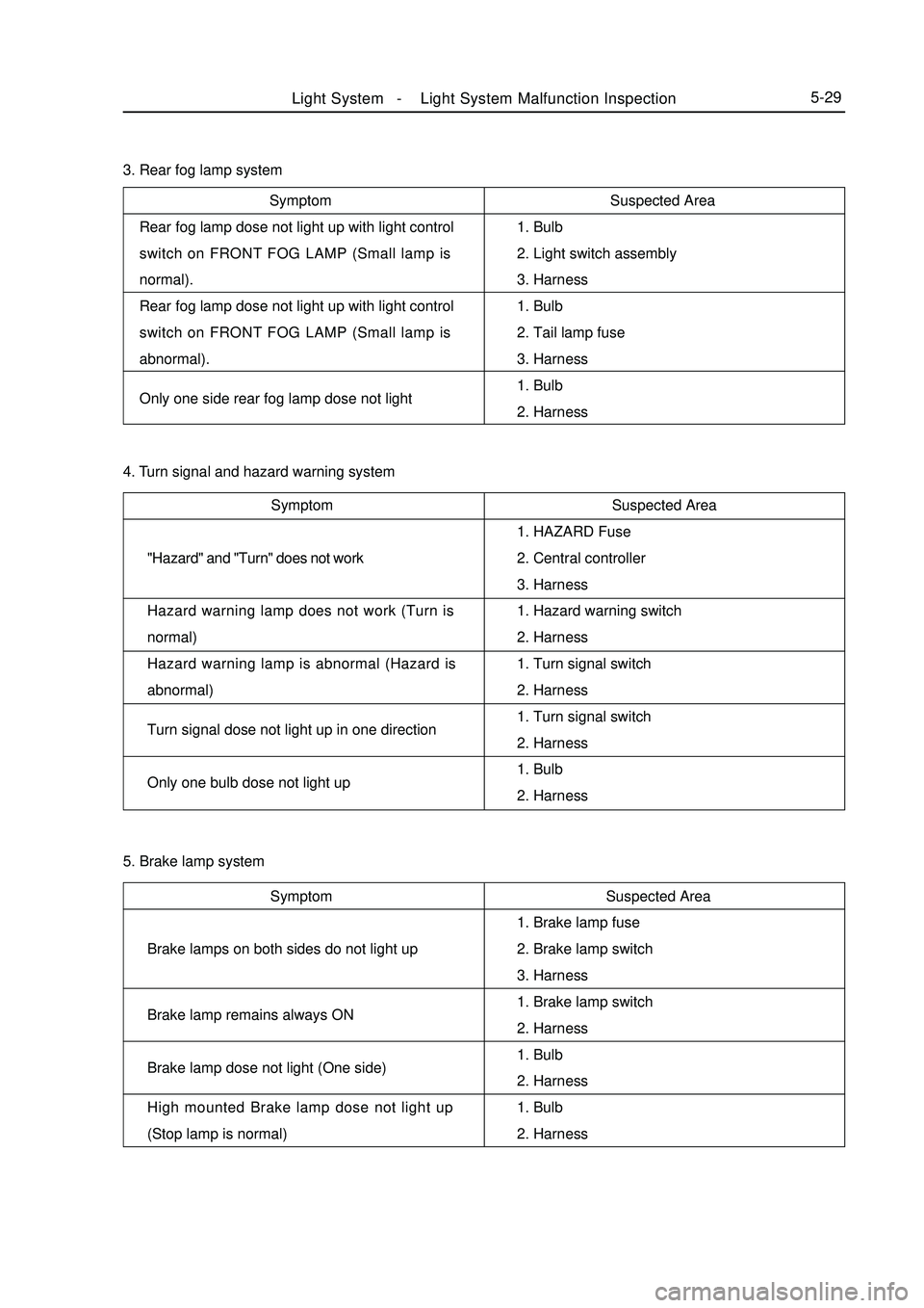
Symptom
Rear fog lamp dose not light up with light control
switch on FRONT FOG LAMP (Small lamp is
normal).
Rear fog lamp dose not light up with light control
switch on FRONT FOG LAMP (Small lamp is
abnormal).
Only one side rear fog lamp dose not lightSuspected Area
1. Bulb
2. Light switch assembly
3. Harness
1. Bulb
2. Tail lamp fuse
3. Harness
1. Bulb
2. Harness 3. Rear fog lamp system
Symptom
"Hazard" and "Turn" does not work
Hazard warning lamp does not work (Turn is
normal)
Hazard warning lamp is abnormal (Hazard is
abnormal)
Turn signal dose not light up in one direction
Only one bulb dose not light upSuspected Area
1. HAZARD Fuse
2. Central controller
3. Harness
1. Hazard warning switch
2. Harness
1. Turn signal switch
2. Harness
1. Turn signal switch
2. Harness
1. Bulb
2. Harness
Symptom
Brake lamps on both sides do not light up
Brake lamp remains always ON
Brake lamp dose not light (One side)
High mounted Brake lamp dose not light up
(Stop lamp is normal)4. Turn signal and hazard warning system
5. Brake lamp system
Suspected Area
1. Brake lamp fuse
2. Brake lamp switch
3. Harness
1. Brake lamp switch
2. Harness
1. Bulb
2. Harness
1. Bulb
2. HarnessLight System -Light System Malfunction Inspection5-29
Page 219 of 416

Switch motion Testing terminal Status
ON
1-2 ON
(gear lever is in reverse gear)
OFF 1-2 OFFSwitch position Testing terminal Status
OFF EL2-FF-RF OFF
Front foglight EL2-FF ON
Rear foglight EL2-FF-RF ONSwitch position Testing terminal Status
Low beam EL1-HL ON
High beam EL1-HU ON
PASSING EL1-HU-PASS ON (2) Check whether headlight dimmer switch is connected
Check whether terminals are connected when switch is in each position according to the table.
If it does not meet stipulation, replace the switch.
(3) Check whether direction indicator switch is connected
Check whether terminals are connected when switch is in each position according to the table.
If it doest not meet stipulation, replace the switch.
(4) Check whether front and rear foglight switch is connected
Check whether terminals are connected when switch is in each position according to the table.
If it doest not meet stipulation, replace the switch.
2. Reversing light switch assembly
Check whether reversing light switch assembly is connected
Check whether two terminals are connected when switch works
according to the tableSwitch position Testing terminal Status
Left turn FU-TL ON
Straight ahead FU-TL-TR OFF
Right turn FU-TR ON
If it doest not meet stipulation, replace the switch.
3. Brake lamp switch assembly
Check whether brake lamp switch assembly is connected
Check whether two terminals are connected when brake lamp
switch works
If it doest not meet stipulation, replace the switch.Step down brake pedal 1-2 ON
Release brake pedal 1-2 OFF2 1Light System -Light System Malfunction Inspection5-321
2 ON
OFFRelease PushSwitch motionTesting terminal Status
Page 287 of 416
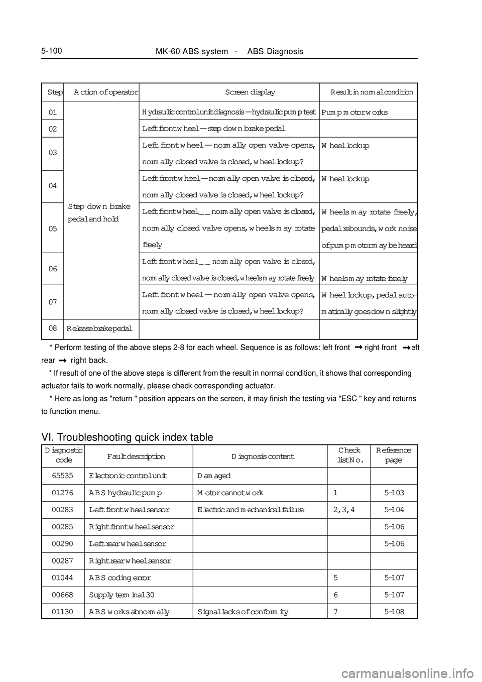
Step Action of operator Screen displayResult in normal conditionPump motor works
Wheel lockup
Wheel lockup
Wheels may rotate freely,
pedal rebounds, work noise
of pump motor may be heard
Wheels may rotate freely
Wheel lockup, pedal auto-
matically goes down slightlyHydraulic control unit diagnosis -- hydraulic pump testLeft front wheel -- step down brake pedal
Left front wheel -- normally open valve opens,
normally closed valve is closed, wheel lockup?
Left front wheel -- normally open valve is closed,
normally closed valve is closed, wheel lockup?
Left front wheel _ _ normally open valve is closed,
normally closed valve opens, wheels may rotate
freelyLeft front wheel _ _ normally open valve is closed,
normally closed valve is closed, wheels may rotate freelyLeft front wheel -- normally open valve opens,
normally closed valve is closed, wheel lockup?
Release brake pedal 01
02
03
04
05
06
07
08Step down brake
pedal and hold
* Perform testing of the above steps 2-8 for each wheel. Sequence is as follows: left front right front left
rear right back.
* If result of one of the above steps is different from the result in normal condition, it shows that corresponding
actuator fails to work normally, please check corresponding actuator.
* Here as long as "return " position appears on the screen, it may finish the testing via "ESC " key and returns
to function menu.VI. Troubleshooting quick index tableMK-60 ABS system - ABS Diagnosis5-100Diagnostic
codeFault description Diagnosis contentCheck
list No.Reference
page
65535
01276
00283
00285
00290
00287
01044
00668
01130Electronic control unit
ABS hydraulic pump
Left front wheel sensor
Right front wheel sensor
Left rear wheel sensor
Right rear wheel sensor
ABS coding error
Supply terminal 30
ABS works abnormallyDamaged
Motor cannot work
Electric and mechanical failure
Signal lacks of conformity5-103
5-104
5-106
5-106
5-107
5-107
5-108 1
2, 3, 4
5
6
7