window GEELY MK 2008 Workshop Manual
[x] Cancel search | Manufacturer: GEELY, Model Year: 2008, Model line: MK, Model: GEELY MK 2008Pages: 416, PDF Size: 25.19 MB
Page 8 of 416
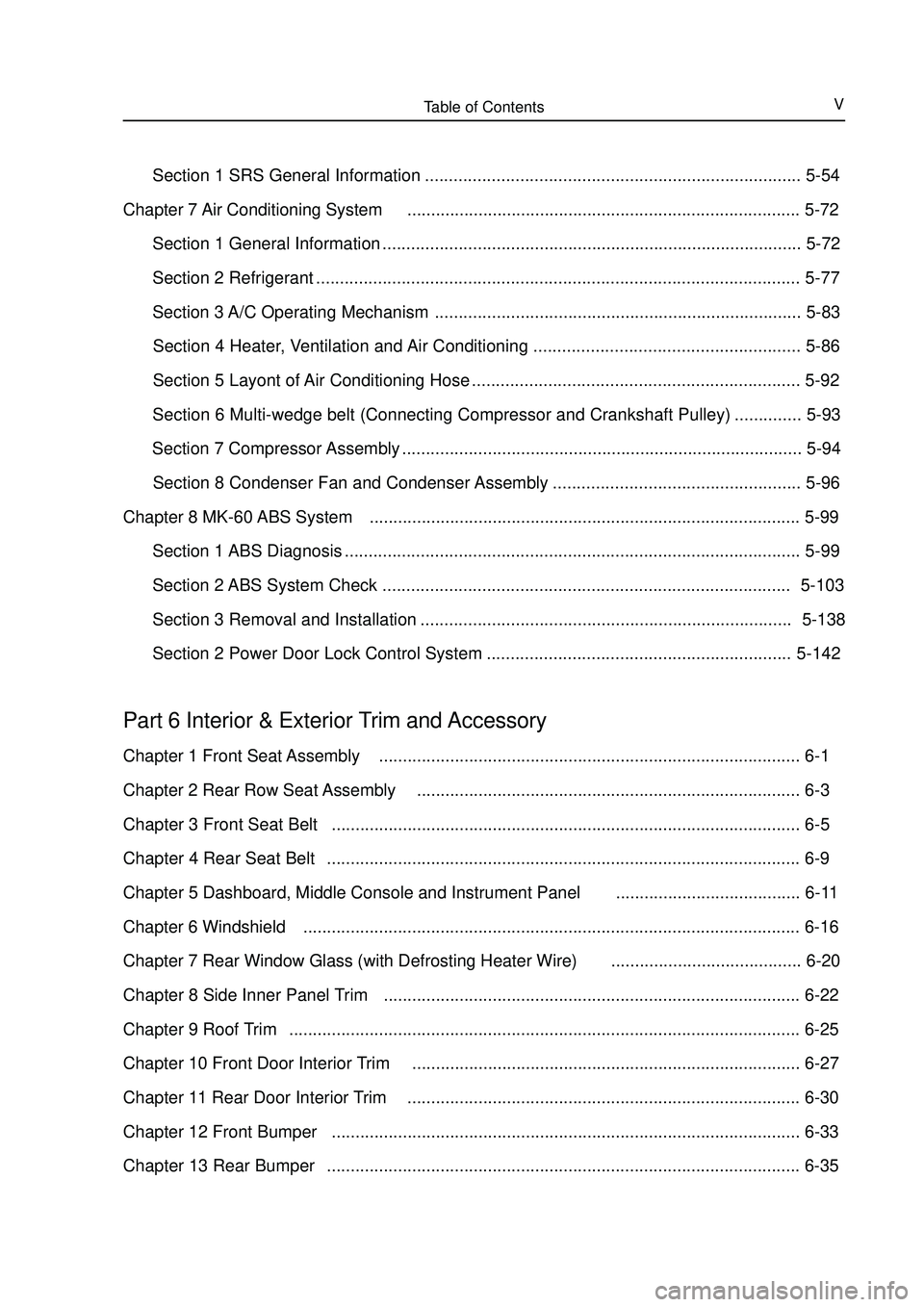
Table of ContentsV Section 1 SRS General Information ............................................................................... 5-54
Chapter 7 Air Conditioning System................................................................................... 5-72
Section 1 General Information ........................................................................................ 5-72
Section 2 Refrigerant ...................................................................................................... 5-77
Section 3 A/C Operating Mechanism ............................................................................. 5-83
Section 4 Heater, Ventilation and Air Conditioning ........................................................ 5-86
Section 5 Layont of Air Conditioning Hose ..................................................................... 5-92
Section 6 Multi-wedge belt (Connecting Compressor and Crankshaft Pulley) .............. 5-93
Section 7 Compressor Assembly .................................................................................... 5-94
Section 8 Condenser Fan and Condenser Assembly .................................................... 5-96
Chapter 8 MK-60 ABS System........................................................................................... 5-99
Section 1 ABS Diagnosis ................................................................................................ 5-99
Section 2 ABS System Check ...................................................................................... 5-103
Section 3 Removal and Installation .............................................................................. 5-138
Section 2 Power Door Lock Control System ................................................................5-142Part 6 Interior & Exterior Trim and AccessoryChapter 1 Front Seat Assembly......................................................................................... 6-1
Chapter 2 Rear Row Seat Assembly................................................................................. 6-3
Chapter 3 Front Seat Belt................................................................................................... 6-5
Chapter 4 Rear Seat Belt.................................................................................................... 6-9
Chapter 5 Dashboard, Middle Console and Instrument Panel....................................... 6-11
Chapter 6 Windshield......................................................................................................... 6-16
Chapter 7 Rear Window Glass (with Defrosting Heater Wire)........................................ 6-20
Chapter 8 Side Inner Panel Trim........................................................................................ 6-22
Chapter 9 Roof Trim............................................................................................................ 6-25
Chapter 10 Front Door Interior Trim.................................................................................. 6-27
Chapter 11 Rear Door Interior Trim................................................................................... 6-30
Chapter 12 Front Bumper................................................................................................... 6-33
Chapter 13 Rear Bumper.................................................................................................... 6-35
Page 25 of 416
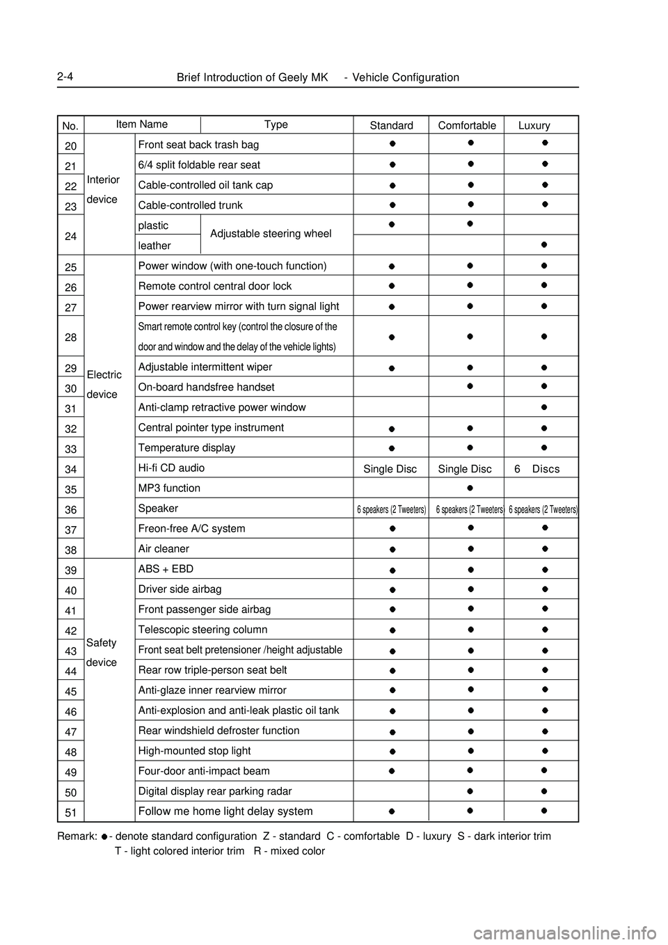
Brief Introduction of Geely MK - Vehicle Configuration2-4Electric
deviceInterior
deviceAdjustable steering wheelRemark: - denote standard configuration Z - standard C - comfortable D - luxury S - dark interior trim
T - light colored interior trim R - mixed colorType Item Name
No.
20
21
22
23
24
25
26
27
28
29
30
31
32
33
34
35
36
37
38
39
40
41
42
43
44
45
46
47
48
49
50
51Standard Comfortable Luxury
Single Disc Single Disc 6 Discs6 speakers (2 Tweeters) 6 speakers (2 Tweeters) 6 speakers (2 Tweeters)Front seat back trash bag
6/4 split foldable rear seat
Cable-controlled oil tank cap
Cable-controlled trunk
plastic
leather
Power window (with one-touch function)
Remote control central door lock
Power rearview mirror with turn signal lightSmart remote control key (control the closure of the
door and window and the delay of the vehicle lights)Adjustable intermittent wiper
On-board handsfree handset
Anti-clamp retractive power window
Central pointer type instrument
Temperature display
Hi-fi CD audio
MP3 function
Speaker
Freon-free A/C system
Air cleaner
ABS + EBD
Driver side airbag
Front passenger side airbag
Telescopic steering columnFront seat belt pretensioner /height adjustableRear row triple-person seat belt
Anti-glaze inner rearview mirror
Anti-explosion and anti-leak plastic oil tank
Rear windshield defroster function
High-mounted stop light
Four-door anti-impact beam
Digital display rear parking radar
Follow me home light delay systemSafety
device
Page 27 of 416
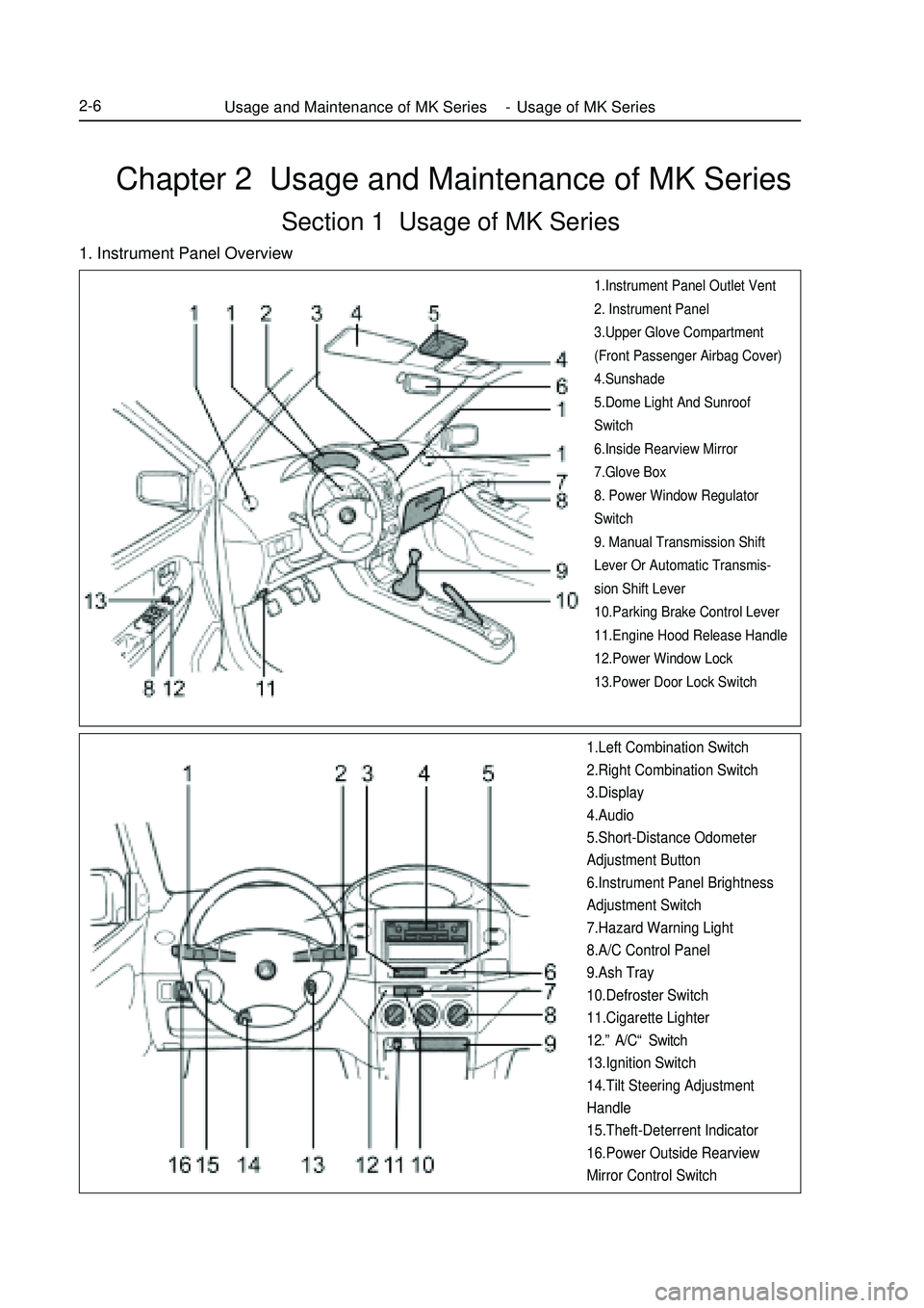
Chapter 2 Usage and Maintenance of MK SeriesSection 1 Usage of MK Series1. Instrument Panel Overview1.Instrument Panel Outlet Vent
2. Instrument Panel
3.Upper Glove Compartment
(Front Passenger Airbag Cover)
4.Sunshade
5.Dome Light And Sunroof
Switch
6.Inside Rearview Mirror
7.Glove Box
8. Power Window Regulator
Switch
9. Manual Transmission Shift
Lever Or Automatic Transmis-
sion Shift Lever
10.Parking Brake Control Lever
11.Engine Hood Release Handle
12.Power Window Lock
13.Power Door Lock Switch1.Left Combination Switch
2.Right Combination Switch
3.Display
4.Audio
5.Short-Distance Odometer
Adjustment Button
6.Instrument Panel Brightness
Adjustment Switch
7.Hazard Warning Light
8.A/C Control Panel
9.Ash Tray
10.Defroster Switch
11.Cigarette Lighter
12.”A/C“ Switch
13.Ignition Switch
14.Tilt Steering Adjustment
Handle
15.Theft-Deterrent Indicator
16.Power Outside Rearview
Mirror Control SwitchUsage and Maintenance of MK Series - Usage of MK Series2-6
Page 239 of 416
Section 4 Audio System ReplacementI. Notice on operation Please explain to the customer that the AM/FM broadcast channel information will be cleared when removing
the battery negative terminal cable. Record the channel information before removing the negative terminal cable
if necessary. Reset after connecting the negative terminal cable.
All cassette tapes and CDs must be taken out before radio removal and installation.
If the cassette tapes and CDs can not be taken out due to radio fault. Do not take them out by force. Drive the
vehicle to Service Station.
Make sure the grounding bolts are tightened before antenna removal and installation.
There will be noise when receiving electric wave if the grounding bolts are not tightened.
Don't touch the speaker cone.II. Radio assembly1. Remove middle instrument board (see internal decorations)
2. Remove radio with bracket assembly
a. Remove four screws
b. Disconnect connector
3. Remove left bracket
a. Remove four screws
4. Remove right bracket
a. Remove four screws
5. Remove radio assemblyAudio System -Audio System Replacement5-52III. Front loudspeaker assembly
1. Remove door handhold
2. Remove front door electric piovted window switch assembly
3. Remove front door decorative internal plate assembly
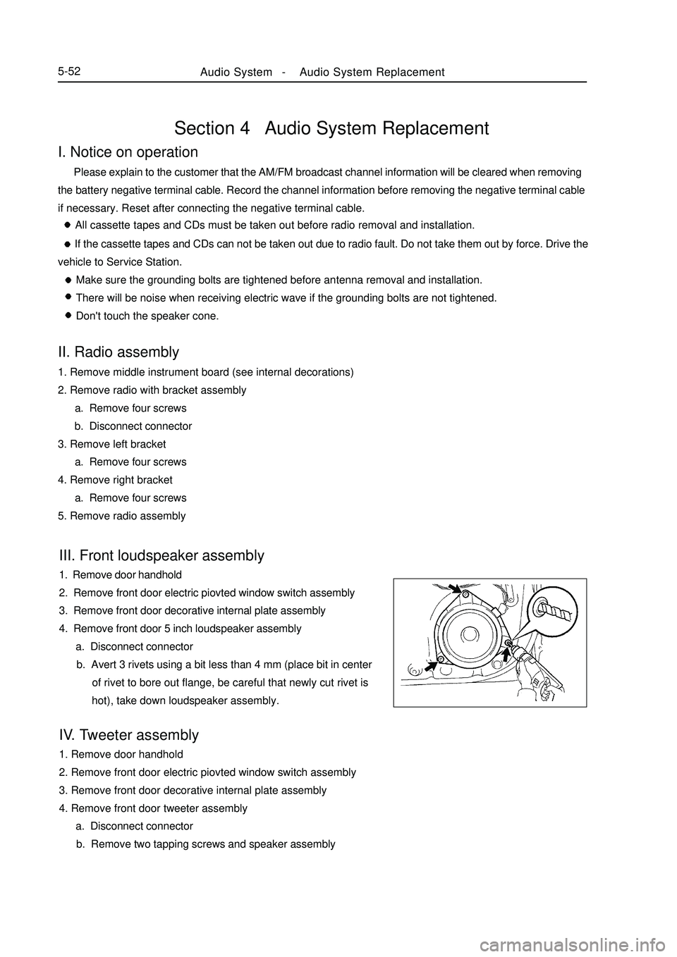
4. Remove front door 5 inch loudspeaker assembly
a. Disconnect connector
b. Avert 3 rivets using a bit less than 4 mm (place bit in center
of rivet to bore out flange, be careful that newly cut rivet is
hot), take down loudspeaker assembly.
IV. Tweeter assembly
1. Remove door handhold
2. Remove front door electric piovted window switch assembly
3. Remove front door decorative internal plate assembly
4. Remove front door tweeter assembly
a. Disconnect connector
b. Remove two tapping screws and speaker assembly
Page 256 of 416

5-69Notice
Work must be started 60s after the positive (+) and negative (-) terminal cables are detached from battery.
3) The airbag assembly shall be deployed according to the following procedures.
(1) Driver airbag assembly
a. Remove the knee bolster.
b. Remove the connector (yellow) that connecting the lower end of the clock spring with the wire harness
of the instrument panel (see the figure below).Notice
Remove the connector of the clock spring from the wire harness of the instrument, the connector will be
short circuited automatically, which can avoid the possible serious accident resulted from the deployment of
the diver airbag assembly due to static electricity.
c. Tie two 6m plus wire harnesses for deployment to the
adaptor wire harness of the airbag, and wrap the connecting points
with insulating tape for insulation.The other ends of the wire harness
for deployment are connected to each other (short circuited). Unex-
pected deployment resulted from static electricity shall be prevented.
d. From the yellow connector of the clock spring, lead the
airbag adapter wire harnesses out of the vehicle by means of the wire
harnesses for deployment (see the figure below).
e. To restrain the noise, close all the windows and doors and
put on the vehicle cover.Notice
The glass will likely break up if there is crack. Vehicle covers shall be put on.
f. Try to disconnect at a location far away from the vehicle the connector of the wire harness for deployment
of the driver airbag assembly, connect them with the two terminals of the battery removed from the
vehicle and deploy the airbag (see the figure below).Notice
Make sure there is no man inside or near the vehicle and then
carry out the operations.
After the driver airbag is deployed, the gas generator is of high
temperature. Keep it for 30 minutes until it gets cool for use.
If the driver airbag assembly cannot be deployed, discuss the
problem with the local Geely service station.Deployed
HarnessCovering the car g. The deployed driver airbag assembly shall be scrapped according to the scrapping procedures.
Deploy outside the vehicleNotice
Keep the airbag over 6m away from a obstacle or person and deploy the airbag in an open flat area.
Deployed the airbag outside the vehicle, avoid to do this job in the strong wind. In case of breeze, fire should
be against the wind.SRS (Supplemental Restraint System)-
SRS-General InformationDAB
Connector Horn
Connector
Page 266 of 416

5-79 Air conditioning switch: switch on
So door is completely open
(1) Refrigerating system meter reading during normal work:
Low pressure side: 0. 15-0. 25MPa
High pressure side: 1. 37-1. 57MPa
(2) System contains moistureSymptom Possible cause Diagnosis Correct treatment 1. During work, pressure
on low pressure side some-
times becomes vacuum
2.Intermittent refrigeration,
finally no refrigerationMoisture in the system
freezes at orifice of expan-
sion valve, circulation
suspends, but system re-
stores to normal after ice
thaws1. Drying agent is in satu-
rated state
2.System moisture
freezes at orifice of ex-
pansion valve, obstructs
refrigerant circulation1. Replace stock solution dry-
ing agent
2. By drawing off air repeti-
tively to remove water vapor in
the system, fill in appropriate
quantity of new refrigerant Pressure gauge indication when there is moisture in the system (3) Poor coolingManifold pressure gauge indication in case of poor cooling1. Pressure on high, low
pressure side is a bit low
2. Successive bubble ap-
pears in glass window
3. Refrigeration efficiency
deterioratesRefrigerant leakage
occurs in refrigerat-
ing system1. System refriger-
ant is insufficient
2. Refrigerant leaks1. Use leak detector to check whether
there is gas leakage, repair if there is any.
2. Fill in appropriate quantity of refriger-
ant
3. Connect a pressure gauge, if pressure
is zero, repair leaking part, and vacuumize
the systemSymptom Possible cause Diagnosis Correct treatmentAir Conditioning System -Refrigerant
Page 268 of 416
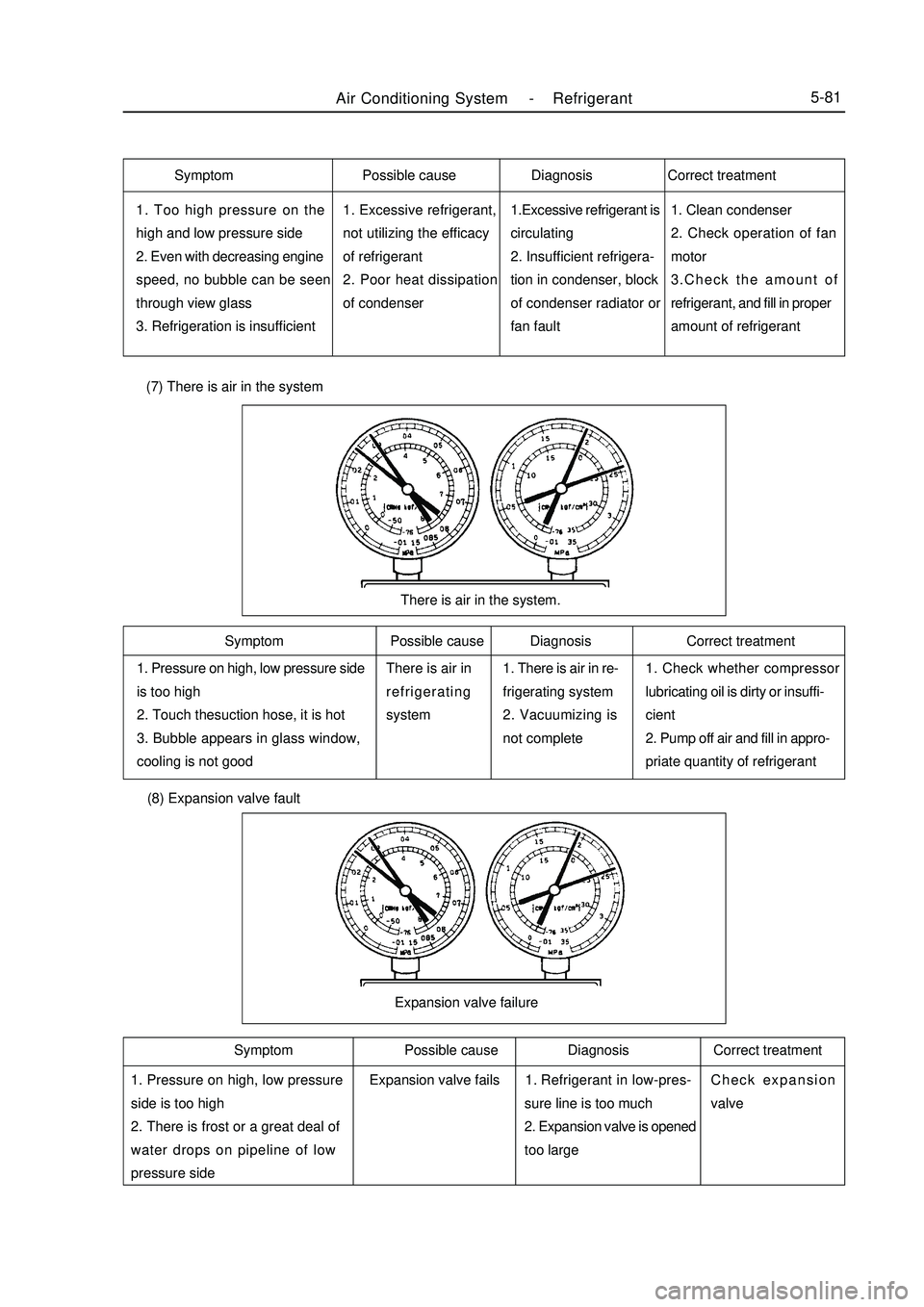
Air Conditioning System -Refrigerant5-811. Too high pressure on the
high and low pressure side
2. Even with decreasing engine
speed, no bubble can be seen
through view glass
3. Refrigeration is insufficient1. Excessive refrigerant,
not utilizing the efficacy
of refrigerant
2. Poor heat dissipation
of condenser1.Excessive refrigerant is
circulating
2. Insufficient refrigera-
tion in condenser, block
of condenser radiator or
fan fault1. Clean condenser
2. Check operation of fan
motor
3.Check the amount of
refrigerant, and fill in proper
amount of refrigerant1. Pressure on high, low pressure side
is too high
2. Touch thesuction hose, it is hot
3. Bubble appears in glass window,
cooling is not goodThere is air in
refrigerating
system1. There is air in re-
frigerating system
2. Vacuumizing is
not complete1. Check whether compressor
lubricating oil is dirty or insuffi-
cient
2. Pump off air and fill in appro-
priate quantity of refrigerantThere is air in the system. (7) There is air in the system (8) Expansion valve fault1. Pressure on high, low pressure
side is too high
2. There is frost or a great deal of
water drops on pipeline of low
pressure sideRefrigerant in low-pres-
sure line is too much
2. Expansion valve is opened
too largeCheck expansion
valveExpansion valve failureSymptom Possible cause Diagnosis Correct treatment
Symptom Possible cause Diagnosis Correct treatment Symptom Possible cause Diagnosis Correct treatment
Expansion valve fails1.
Page 316 of 416

Chapter 10 On-board Vehicle TelephoneI. Key points for use of Geely hands-free car telephone: 1. Microphone of hands-free car telephone is installed on the back of steering wheel upright column, away from
driver to ensure talking effect. During talking, do not open window, otherwise noisy wind might influence talking
effect.
2. Since there are many kinds of mobile phones in Chinese market, in order to ensure talking effect, please
select interface line corresponding to your mobile phone, otherwise talking effect might be influenced. At present,
Nokia, Motorola, Siemens interface lines are available.
3. To use, insert one end of mobile phone interface line into 8 core RJ 45 stand on automobile panel, connect
the other end to earphone output port of the mobile phone. When mobile phone is not connected, automobile sound
works normally, when mobile phone receive a call, CD becomes quiet automatically, at the same time, loudspeaker
in the vehicle is switched to hands-free telephone output. This hands-free car telephone is provided with response
button at the top of microphone, however, new style of mobile phone does not support manual response function
for the time being, while supports automatic response function, namely it receive the call automatically after
ringing for three times.
4. After talking is finished, automobile sound will return to original state automatically.
5. During daily use, note that contact insertion and withdraw force of mobile phone interface line should not
be too large, so as to avoid damage.
6. Hands-free car telephone has no volume switch, volume of loudspeaker voice may be adjusted by regulating
the volume of handset earphone.II. Circuit diagram5-129On Board Vehicle Telephone-On-board Vehicle TelephonePlease Refer to "MK WIRING DIAGRAM"
Page 320 of 416

Centralized Controller System-
Function Inspectior5-133Chapter 12 Centralized Controller SystemSection 1 Function InspectiorI. Glass frame riser: 1. Glass frame riser may be operated to move within 60s after ignition switch is turned on or off; 60s after
ignition switch is turned off, glass frame riser cannot be operated to move;
2. Manual rise: press corresponding glass frame riser switch rise key, corresponding glass frame riser motor
works, glass frame rises, release rise key, it stops.
3. Manual fall: press corresponding glass frame riser switch fall key (hold time 300ms), corresponding glass
frame riser motor works, glass frame falls, release fall key, it stops.
4. Automatic fall: press corresponding glass frame riser switch fall key (hold time < 300 ms), corresponding
glass frame riser motor works, glass frame falls down to end; or fall down until rise key or fall key is pressed again.
Note:
During automatic fall of glass frame, if corresponding glass frame riser switch fall key is pressed down for more
than 300 ms, glass frame riser is changed to manual fall mode; if corresponding glass frame riser switch rise key
is pressed down for more than 300ms, glass frame riser stops work.
5. Remote window closing:
In case of remote protection, if a key is pressed down for more than 1s, perform glass frame riser automatic
rise action, left front, right front, left rear, right rear in turn.II. Central lock: 1. In case protection is deactivated, use a key to open left front door switch or press internal unlock switch to
open four door fasteners; close left front door switch, close four door fasteners.
2. Remote unlock /lock:
(1) Ignition switch opening
a. Press remote control unlock key to open four door fasteners;
b. Press remote lock key to close four door fasteners;
(2) Turn off ignition switch
a. Press remote unlock key to open four front door fasteners, at the same time turn light flashes once.
b. Press remote lock key to close four door fasteners, at the same time turn light flashes twice.
(3) When door is opened, press remote fastener, turn light will flash for three times, at the same time electric
horn beeps for three times.
(4) If the system is triggered in anti-theft condition, when remote unlock system exits protection state,
directional turn signal will flash for four times, at the same time, electric horn beeps for four times.
3. Automatic lock
When vehicle speed exceeds 30km/h, three doors will be closed.
4. Door lock priority
Central door lock should not act simultaneously with glass frame riser; when they conflict with each other,
central door lock acts with priority, while glass frame riser stops; after central door lock action is finished, glass
frame riser continue its work in previous condition.III. Front womdscreem wiper: After spray water signal is finished, the wiper acts twice.
Page 323 of 416

Terminal No.
B1
2
3
4
5
6
7
8
9
10
11
12
1
2
3
4
5
6
7
8
9
10
11
12
13
14
15
16
17
18
19
20
21
22
23
24
25G
G
RY
Br
GB
GW
BLW
Br
RB
RB
YB
YB
RBL
RBL
GBL
R
RW
RW
BR
WR
BL
W
WB
BLB
R
BLB
WB
BLY
WY
RBHazard lamp power supply
Hazard lamp power supply
Dome lamp
Wiper motor (INT)
GND
GND
Right turn light and its indicator lamp
Left turn light and its indicator lamp
IG2
Wiper switch 3#Head light relay 85 #Head light relay 85 #Rear air window defrost and indicator lamp
Rear air window defrost and indicator lamp
Rear air window defrost power supply
Rear air window defrost power supply
GND
Horn relay 85 #Electric glass frame power supply
GND
GND
Fastener power supply
Right front, right rear, left rear fastener
Right front, right rear, left rear fastener
Left actuator
Front left glass regulator
Front left glass regulator
GND
Front right glass regulator
Front right glass regulator
Glass power supply
Rear left glass regulator
Rear left glass regulator
GND
Rear Right glass regulator
Rear Right glass regulator
Left actuatorConductor color Terminal definitionCReplacement ( 1 ) Remove dashboard subassembly (refer to trim)
( 2 ) Remove two bolts5-136Centralized Controller System-
Function Inspectior