clutch GEELY MK 2008 User Guide
[x] Cancel search | Manufacturer: GEELY, Model Year: 2008, Model line: MK, Model: GEELY MK 2008Pages: 416, PDF Size: 25.19 MB
Page 71 of 416

The valve body fails.
12. The vehicle shifts before or after some gear points in the running status.
The vehicle switch or parking switch fails.
13. The vehicle has poor acceleration in running.
(1)The clutch or brake fails.
(2)The engine system fails.
14. The vehicle vibrates when it runs at a constant speed or accelerating speed.
(1)The hydraulic torque clutch pressure or hydraulic torque meter fails.
(2)The engine system or valve fails.
15. The acceleration switch system fails.
(1)The acceleration switch or ignition switch fails.
(2)The connector or automatic transmission control unit fails.I. Automatic transmissions Removal1. Put the select lever in "N" position
2. Remove 3 bolts of the flexibility plate (engine side)
3. Remove starter and 2 cooling hoses.
4. Disconnect neutral switch connector and odometer sensor.
5. Loosen the drain screw under the housing to bleed ATF and tighten the drain screw with sealing glue when
assembling. Tightening torque is 29~35N.m
6. Loosen the locking bolt for select lever cable.
7. Remove Drive Shaft LH&RH, using plastic stopper in the oil sealing of differential.
8. Detach suspension bolts.
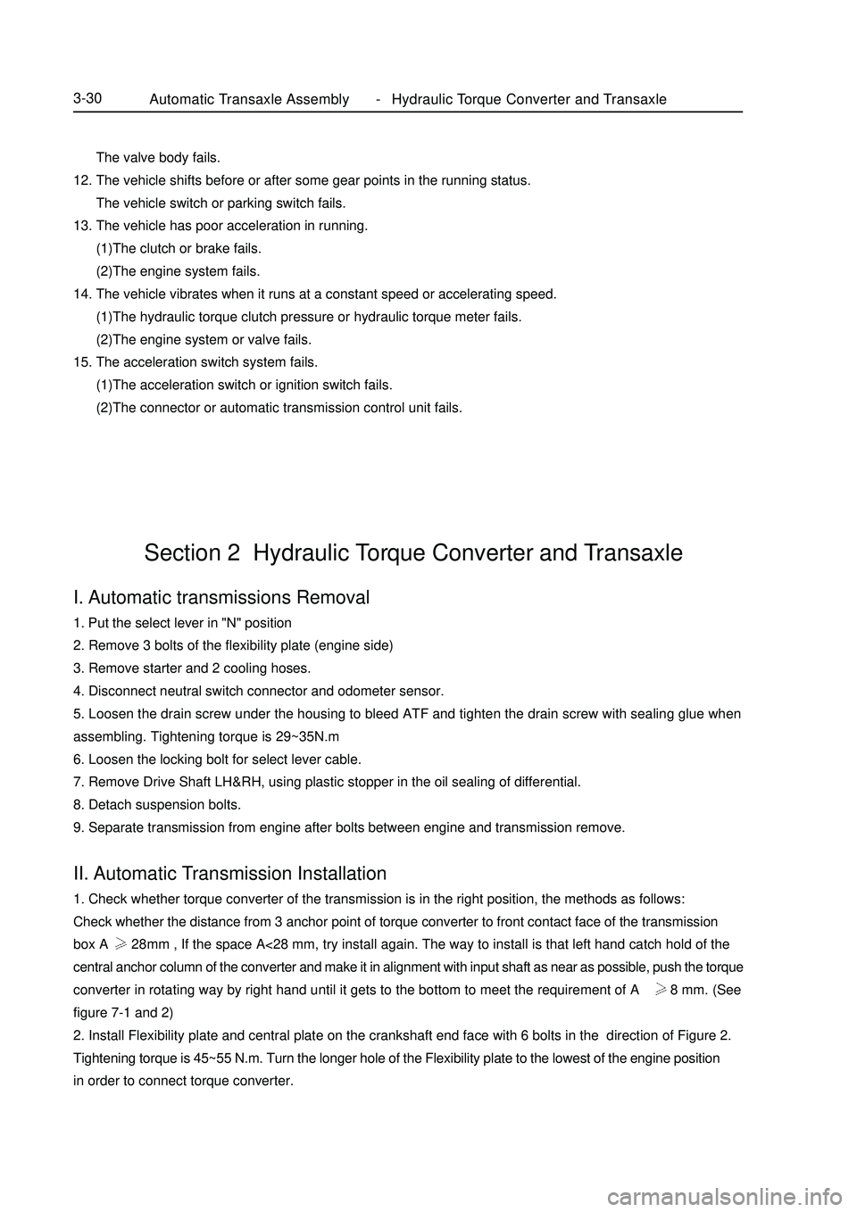
9. Separate transmission from engine after bolts between engine and transmission remove.II. Automatic Transmission Installation1. Check whether torque converter of the transmission is in the right position, the methods as follows:
Check whether the distance from 3 anchor point of torque converter to front contact face of the transmission
box A 28mm , If the space A<28 mm, try install again. The way to install is that left hand catch hold of the
central anchor column of the converter and make it in alignment with input shaft as near as possible, push the torque
converter in rotating way by right hand until it gets to the bottom to meet the requirement of A 28 mm. (See
figure 7-1 and 2)
2. Install Flexibility plate and central plate on the crankshaft end face with 6 bolts in the direction of Figure 2.
Tightening torque is 45~55 N.m. Turn the longer hole of the Flexibility plate to the lowest of the engine position
in order to connect torque converter.Section 2 Hydraulic Torque Converter and TransaxleAutomatic Transaxle Assembly Hydraulic Torque Converter and Transaxle3-30 -
Page 89 of 416

Chapter 3 Clutch Control SystemSection 1 Introduction of Clutch CentrolI. Description A hydraulic clutch control system is equipped which can be used in cars with various displacements (including
1.3L, 1.5L and1.6L).II. Symptom Table The table below lists the common symptoms and possible causes of the failures. The number means the
possible sequence of the causes. Check the parts, and replace the corresponding parts if necessary.
Suspected area
1. Engine fixture is loosened.
2. Clutch disc shakes seriously.
3. Clutch disc is contaminated by oil or wore down.
4. Torque spring of the clutch disc is damaged.
5. Clutch disc is hardened.
6. Diaphragm spring is not aligned on the top.
1. There is air in the clutch oil pipe.
2. Cup of the master cylinder is damaged.
3. Cup of the wheel cylinder is damaged.
1. Clutch release bearing is worn out, contaminated or damaged.
2. Torque spring of the clutch disc is damaged.
1. Clutch pedal has maladjusted free stroke.
2. Clutch disc is contaminated by oil.
3. Clutch disc is worn.
4. Diaphragm spring is damaged.
5. Platen is deformed.
6. Flywheel is deformed.
1. Clutch pedal has maladjusted free stroke.
2. There is air in the clutch oil pipe.
3. Cup of the master cylinder is damaged.
4. Cup of the wheel cylinder is damaged.
5. Clutch disc id deformed or wiggled.
6. Clutch disc is worn out.
7. Clutch disc is contaminated or burned out.
8. Clutch disc is contaminated by oil.
9. Clutch disc has no lube on its spline. Symptom
Clutch is trapped or shaken.
Clutch pedal is loosened.
Abnormal noise occurs.
Clutch skids.
Clutch can not be separated.Clutch Control SystemIntroduction of Clutch Centrol4-12 -
Page 90 of 416

Component ViewSection 2 Clutch PedalAdjustment1. Check and adjust the clutch pedal.
(1) Lift the carpet on the floor.
(2) Check the pedal’s height is proper.
Pedal's height from oil felt: 134.3-144.3mm
(3) Adjust the pedal's height.
Loosen the lock nut, and turn the bolt till the correct pedal's
height is reached, and then tighten the lock nut.
Torque: 16N.m
(4) Check whether the pedal's free travel and push bar travel are
proper.
a. Step the pedal down till a resistance appears.
Pedal's free stroke: 5-15mm
b. Step the pedal down lightly till the resistance increase a
little.
Push bar (on the pedals top) travel: 1.0-5.0mm
(5) Adjust the pedal's free travel and push bar travel.
a. Loosen the lock nut, and turn the push bar till the pedal's
free travel and push bar travel are proper.Clutch pedal bracket
Hex. flange nut37
Clutch pedal spring
Clutch pedal
bushing
Absorber
Clutch pedal cover Clutch pedal
Transimissin RodClutch master cylinder cone
U-connector bushingClutch pedal bushing Clutch Peader AxisClip12
Master cylinder
outtet pipesetSted Band ClampMaster cylinder
Inlet hoseHydranlic clutch hose
ÒLÓ Clip
Clutch hose Bracket
BoltClutch Control SystemClutch Pedal4-13Non-reusable parts
Multi-function lubeNm :Specified torquePedal height
adjustmentClutch
pedal Travel
Push travel &
free travel adjustment
pointPedal heightPedal free travel -
Page 91 of 416

b. Tighten the lock nut.
Torque: 12N.m
c. Check the pedal's height after adjusting the pedal's free
travel.
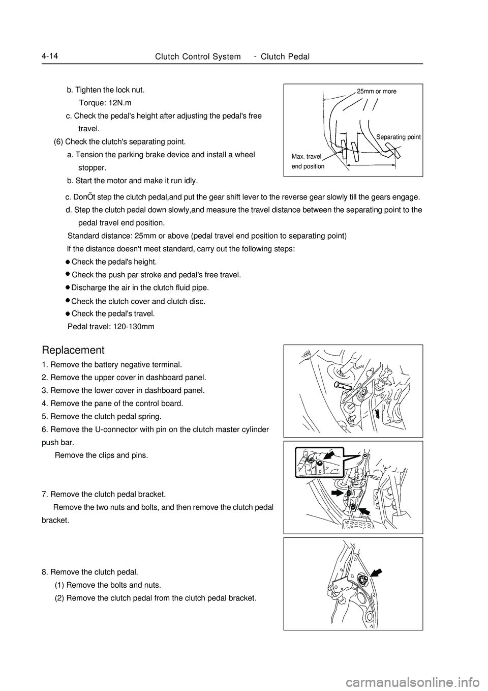
(6) Check the clutch's separating point.
a. Tension the parking brake device and install a wheel
stopper.
b. Start the motor and make it run idly. c. DonÕt step the clutch pedal,and put the gear shift lever to the reverse gear slowly till the gears engage.
d. Step the clutch pedal down slowly,and measure the travel distance between the separating point to the
pedal travel end position.
Standard distance: 25mm or above (pedal travel end position to separating point)
If the distance doesn't meet standard, carry out the following steps:
Check the pedal's height.
Check the push par stroke and pedal's free travel.
Discharge the air in the clutch fluid pipe.
Check the clutch cover and clutch disc.
Check the pedal's travel.
Pedal travel: 120-130mmReplacement1. Remove the battery negative terminal.
2. Remove the upper cover in dashboard panel.
3. Remove the lower cover in dashboard panel.
4. Remove the pane of the control board.
5. Remove the clutch pedal spring.
6. Remove the U-connector with pin on the clutch master cylinder
push bar.
Remove the clips and pins.
7. Remove the clutch pedal bracket.
Remove the two nuts and bolts, and then remove the clutch pedal
bracket.
8. Remove the clutch pedal.
(1) Remove the bolts and nuts.
(2) Remove the clutch pedal from the clutch pedal bracket.Clutch Control SystemClutch Pedal4-1425mm or more
Separating point
Max. travel
end position -
Page 92 of 416

Clutch Control SystemClutch Pedal4-159. Remove the clutch pedal gasket.
10. Remove the clutch pedal absorber.
Remove absorber from the clutch pedal.
11. Remove the clutch pedal bushing.
Remove the two bushings from the clutch pedal.
12. Remove the U-connector bushing on the clutch master cylinder's
push bar.
Remove the U-connector bushing from the clutch pedal with an
8mm hexagon wrench and hammer.
13. Install the U-connector bushing on the clutch master cylinder
push bar.
(1) Apply multi-function lube inside the new U-connector bushing.
(2) Install the U-connector bushing on the clutch pedal.
Tips: Install the U-connector bushing from the right side.
14. Install the clutch pedal bushing.
(1) Apply multi-function lube on both sides of the two new
bushings.
(2) Install the two bushings on the clutch pedal.
15. Install absorber on the clutch pedal.
Put absorber on the clutch pedal.
16. Install the clutch pedal.
Install the clutch pedal on the clutch pedal bracket with bolts and
nuts.
Torque: 37N.m
Tips: Install the bolts from the left side. -
Page 93 of 416

Clutch Control SystemClutch Pedal4-1617. Install the clutch pedal bracket.
Install the clutch bracket with two bolts and nuts.
Torque: 12N.m
18. Install the U-connector with pin on the clutch master cylinder
push bar.
(1) Apply multi-function lube on the surfaces of the pin and the
U-connector bushing.
(2) Connect the U-connector to the clutch pedal with clip.
Tips: Install the pin from the right side.
(3) Install the clip on the pin.
19. Install the clutch pedal spring.
20. Check and adjust the clutch pedal.
21. Connect the battery negative terminal. -
Page 162 of 416

Component ViewSection 4 Brake Master Cylinder AssemblyVacuum boosterBrake System -Brake Master Cylinder Assembly4-85Brake master cylinder
sub-assembly
Vacuum tube
Fluid level indicator lamp connector Manual Transmission
#1 clutch fluidr tank pipe No ABS
specified torqueN.
m :
Page 164 of 416

Repair1. Discharge the brake fluid.
Note: Never spray the brake fluid on the paint surface, otherwise
wash it immediately.
2. Remove the brake master cylinder.
(1) Pull out the connector of the level alarm light switch.
(2) Slide the clip, and pull out #1 clutch storage tank pipe (manual
transaxle).
(3) Remove the two brake pipes from the brake master cylinder
with special tool.(with ABS)
(4) Remove the three brake pipes from the brake master cylinder
accessory with special tool. (without ABS)
(5) Remove the two lock nuts, and pull out the brake master
pump.
3. Remove the storage tank.
(1) Put the brake master cylinder on the bench clamp.
(2) Remove the pin from the brake master cylinder body with
punch and hammer.
(3) Pull out the Brake fluid reservoir.
(4) Remove the cover and strainer from the storage tank.
(5) Remove the storage tank and the two hole connectors.
4. Remove the brake master cylinder.
(1) Put the brake master cylinder on the bench clamp.
(2) Remove the O-ring.
(3) Push the piston with hand, and remove the snap ring with
snap ring pliers.Brake System -Brake Master Cylinder Assembly4-87With ABS:
Without ABS
Page 167 of 416

Brake System -Brake Master Cylinder Assembly4-90 (4) Adjust the length of the vacuum booster push bar with the
special tool till the push bar touches the mandril head.
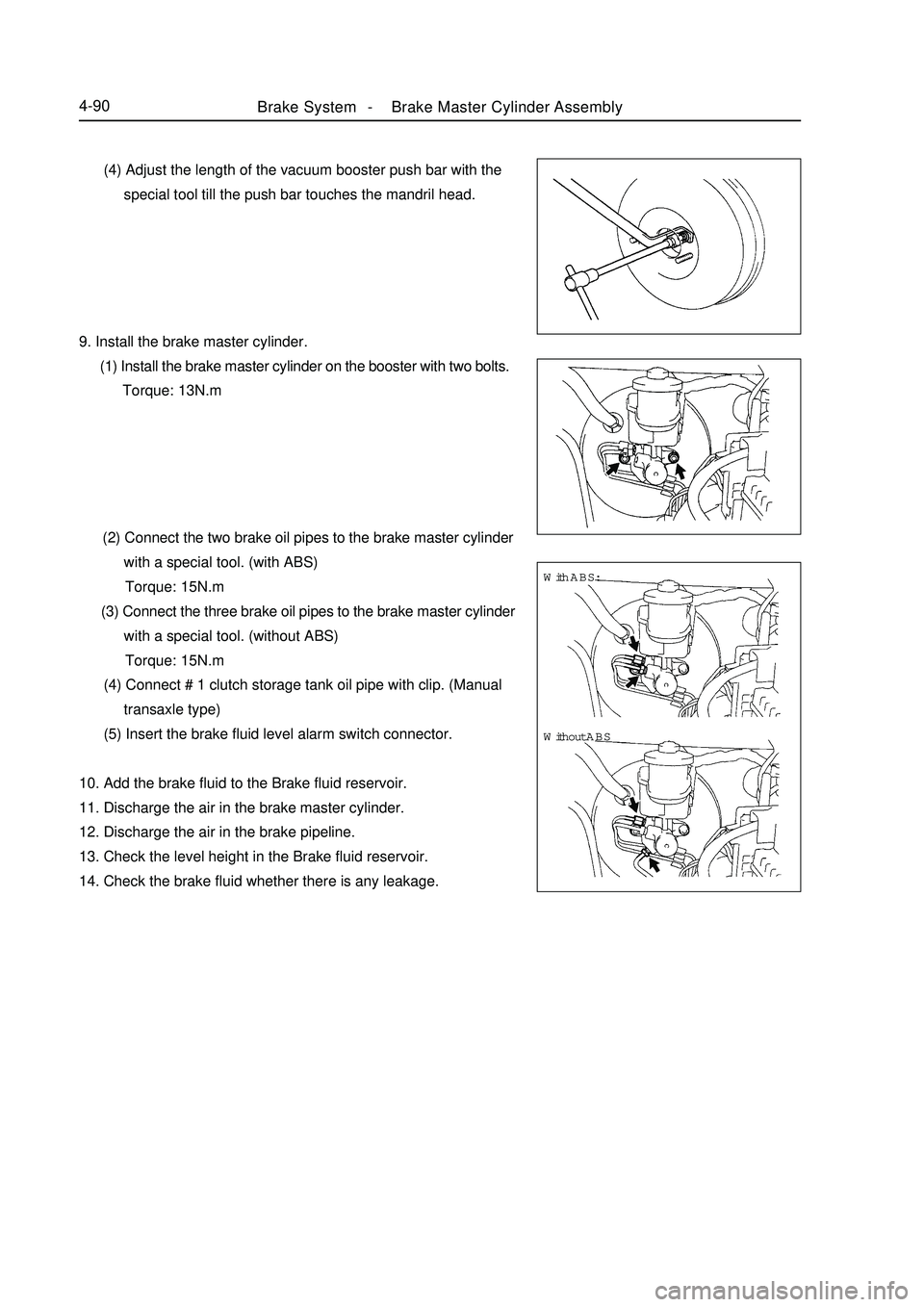
9. Install the brake master cylinder.
(1) Install the brake master cylinder on the booster with two bolts.
Torque: 13N.m
(2) Connect the two brake oil pipes to the brake master cylinder
with a special tool. (with ABS)
Torque: 15N.m
(3) Connect the three brake oil pipes to the brake master cylinder
with a special tool. (without ABS)
Torque: 15N.m
(4) Connect # 1 clutch storage tank oil pipe with clip. (Manual
transaxle type)
(5) Insert the brake fluid level alarm switch connector.
10. Add the brake fluid to the Brake fluid reservoir.
11. Discharge the air in the brake master cylinder.
12. Discharge the air in the brake pipeline.
13. Check the level height in the Brake fluid reservoir.
14. Check the brake fluid whether there is any leakage.With ABS:
Without ABS
Page 168 of 416

19151915131515
Fluid level indicator lamp connectorVacuum booster assembly
Gasket25Clip26 Clip Master cylinder
Manual Transmission
#1 clutch fluid tank oil pipe
HECU assemblyClipSection 5 Vacuum BoosterComponent ViewBrake System -Vacuum Booster4-91Battery
#2 relay box, engine chamber
Return spring
Pin
Push bar
U-connector Without ABSVacuum tube
Non-reusable parts
Lithium soap base glycol lubeSpecified torque