clutch GEELY MK 2008 Workshop Manual
[x] Cancel search | Manufacturer: GEELY, Model Year: 2008, Model line: MK, Model: GEELY MK 2008Pages: 416, PDF Size: 25.19 MB
Page 5 of 416
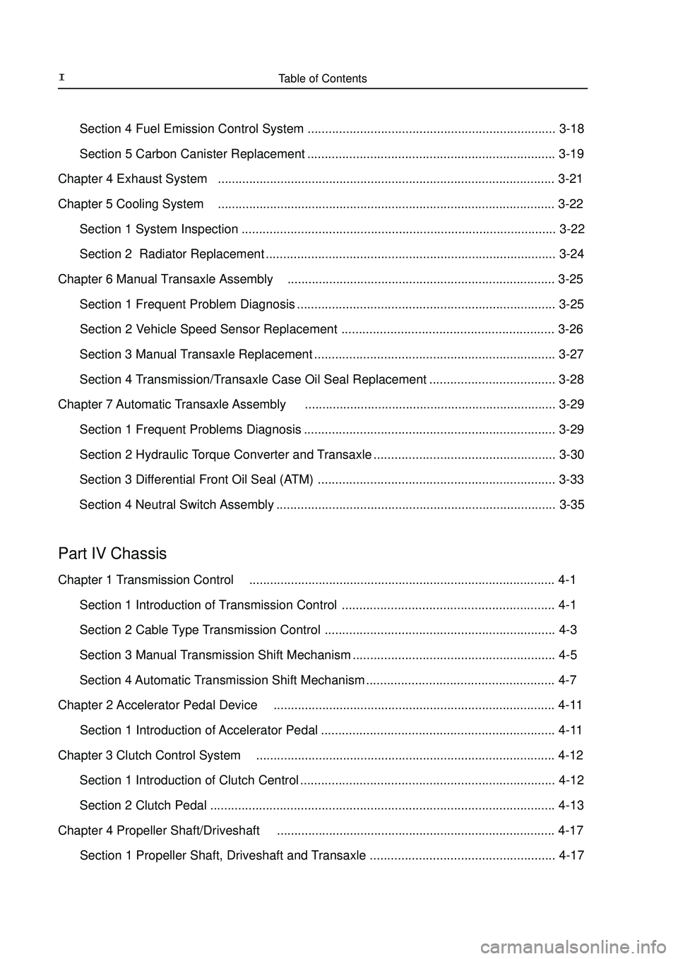
Table of Contents II Section 4 Fuel Emission Control System ....................................................................... 3-18
Section 5 Carbon Canister Replacement ....................................................................... 3-19
Chapter 4 Exhaust System................................................................................................. 3-21
Chapter 5 Cooling System................................................................................................. 3-22
Section 1 System Inspection .......................................................................................... 3-22
Section 2 Radiator Replacement ................................................................................... 3-24
Chapter 6 Manual Transaxle Assembly............................................................................. 3-25
Section 1 Frequent Problem Diagnosis .......................................................................... 3-25
Section 2 Vehicle Speed Sensor Replacement ............................................................. 3-26
Section 3 Manual Transaxle Replacement ..................................................................... 3-27
Section 4 Transmission/Transaxle Case Oil Seal Replacement .................................... 3-28
Chapter 7 Automatic Transaxle Assembly........................................................................ 3-29
Section 1 Frequent Problems Diagnosis ........................................................................ 3-29
Section 2 Hydraulic Torque Converter and Transaxle .................................................... 3-30
Section 3 Differential Front Oil Seal (ATM) .................................................................... 3-33
Section 4 Neutral Switch Assembly ................................................................................ 3-35Part IV ChassisChapter 1 Transmission Control........................................................................................ 4-1
Section 1 Introduction of Transmission Control ............................................................. 4-1
Section 2 Cable Type Transmission Control .................................................................. 4-3
Section 3 Manual Transmission Shift Mechanism .......................................................... 4-5
Section 4 Automatic Transmission Shift Mechanism ...................................................... 4-7
Chapter 2 Accelerator Pedal Device................................................................................. 4-11
Section 1 Introduction of Accelerator Pedal ................................................................... 4-11
Chapter 3 Clutch Control System...................................................................................... 4-12
Section 1 Introduction of Clutch Centrol ......................................................................... 4-12
Section 2 Clutch Pedal ...................................................................................................4-13
Chapter 4 Propeller Shaft/Driveshaft................................................................................ 4-17
Section 1 Propeller Shaft, Driveshaft and Transaxle ..................................................... 4-17
Page 23 of 416
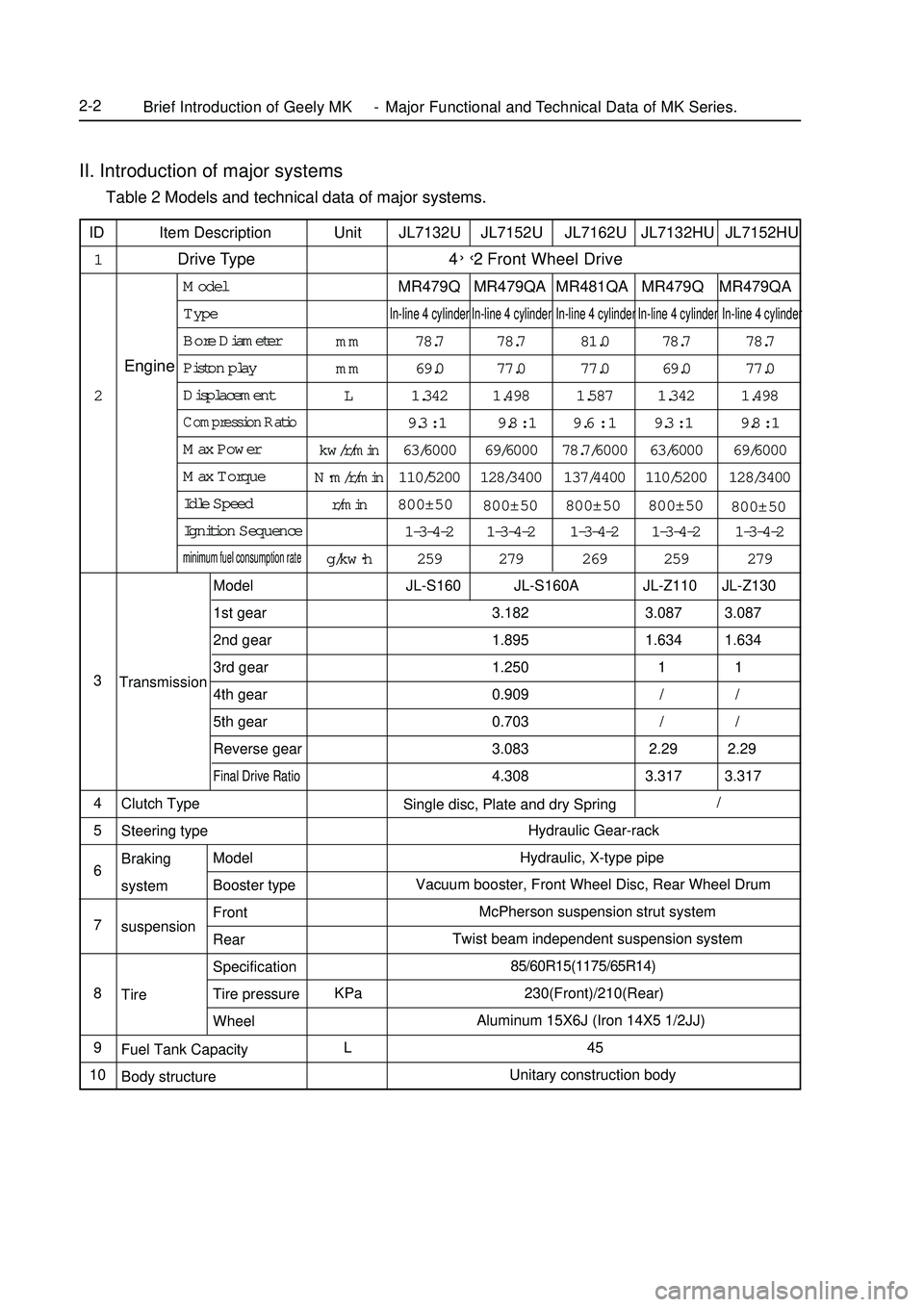
II. Introduction of major systems Table 2 Models and technical data of major systems.
JL7132U JL7152U JL7162U JL7132HU JL7152HU
4
MR479Q MR479QA MR481QA MR479Q MR479QAIn-line 4 cylinder In-line 4 cylinder In-line 4 cylinder In-line 4 cylinder In-line 4 cylinder78.7 78.7 81.0 78.7 78.7
69.0 77.0 77.0 69.0 77.0
1.342 1.498 1.587 1.342 1.498
9.3 : 1 9.8 : 19.6 : 19.3 : 1 9.8 : 1
63/6000 69/6000 78.7/6000 63/6000 69/6000
110/5200 128/3400 137/4400 110/5200 128/3400
800±50
1-3-4-2 1-3-4-2 1-3-4-2 1-3-4-2 1-3-4-2
259 279 269 259 279
JL-S160 JL-S160A JL-Z110 JL-Z130
3.182 3.087 3.087
1.895 1.634 1.634
1.250 1 1
0.909 / /
0.703 / /
3.083 2.29 2.29
4.308 3.317 3.317
Hydraulic Gear-rack
Hydraulic, X-type pipe
Vacuum booster, Front Wheel Disc, Rear Wheel Drum
McPherson suspension strut system
Twist beam independent suspension system
85/60R15(1175/65R14)
230(Front)/210(Rear)
Aluminum 15X6J (Iron 14X5 1/2JJ)
45
Unitary construction body Unit
mm
mm
L
kw/r/min
N.
m/r/min
r/min
g/kw.
h
KPa
L Item Description
Drive Type ID
1
2
3
4
5
6
7
8
9
10EngineModel
Type
Bore Diameter
Piston play
DisplacementCompression RatioMax Power
Max Torque
Idle Speed
Ignition Sequenceminimum fuel consumption rateTransmission
Braking
system
suspension
Tire Clutch Type
Steering type
Model
Booster type
Front
Rear
Specification
Tire pressure
Wheel
Fuel Tank Capacity
Body structureSingle disc, Plate and dry SpringBrief Introduction of Geely MK - Major Functional and Technical Data of MK Series.2-2Model
1st gear
2nd gear
3rd gear
4th gear
5th gear
Reverse gearFinal Drive Ratio /Front Wheel Drive ›‹
2
800±50800±50
800±50
800±50
Page 29 of 416
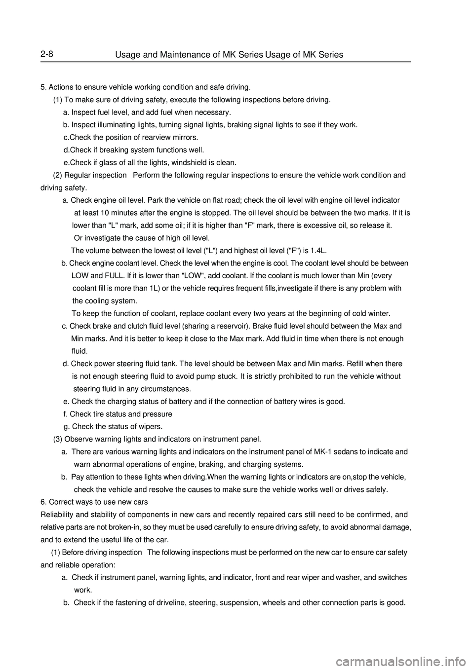
2-85. Actions to ensure vehicle working condition and safe driving.
(1) To make sure of driving safety, execute the following inspections before driving.
a. Inspect fuel level, and add fuel when necessary.
b. Inspect illuminating lights, turning signal lights, braking signal lights to see if they work.
c.Check the position of rearview mirrors.
d.Check if breaking system functions well.
e.Check if glass of all the lights, windshield is clean.
(2) Regular inspection Perform the following regular inspections to ensure the vehicle work condition and
driving safety.
a. Check engine oil level. Park the vehicle on flat road; check the oil level with engine oil level indicator
at least 10 minutes after the engine is stopped. The oil level should be between the two marks. If it is
lower than "L" mark, add some oil; if it is higher than "F" mark, there is excessive oil, so release it.
Or investigate the cause of high oil level.
The volume between the lowest oil level ("L") and highest oil level ("F") is 1.4L.
b. Check engine coolant level. Check the level when the engine is cool. The coolant level should be between
LOW and FULL. If it is lower than "LOW", add coolant. If the coolant is much lower than Min (every
coolant fill is more than 1L) or the vehicle requires frequent fills,investigate if there is any problem with
the cooling system.
To keep the function of coolant, replace coolant every two years at the beginning of cold winter.
c. Check brake and clutch fluid level (sharing a reservoir). Brake fluid level should between the Max and
Min marks. And it is better to keep it close to the Max mark. Add fluid in time when there is not enough
fluid.
d. Check power steering fluid tank. The level should be between Max and Min marks. Refill when there
is not enough steering fluid to avoid pump stuck. It is strictly prohibited to run the vehicle without
steering fluid in any circumstances.
e. Check the charging status of battery and if the connection of battery wires is good.
f. Check tire status and pressure
g. Check the status of wipers.
(3) Observe warning lights and indicators on instrument panel.
a. There are various warning lights and indicators on the instrument panel of MK-1 sedans to indicate and
warn abnormal operations of engine, braking, and charging systems.
b. Pay attention to these lights when driving.When the warning lights or indicators are on,stop the vehicle,
check the vehicle and resolve the causes to make sure the vehicle works well or drives safely.
6. Correct ways to use new cars
Reliability and stability of components in new cars and recently repaired cars still need to be confirmed, and
relative parts are not broken-in, so they must be used carefully to ensure driving safety, to avoid abnormal damage,
and to extend the useful life of the car.
(1) Before driving inspection The following inspections must be performed on the new car to ensure car safety
and reliable operation:
a. Check if instrument panel, warning lights, and indicator, front and rear wiper and washer, and switches
work.
b. Check if the fastening of driveline, steering, suspension, wheels and other connection parts is good.Usage and Maintenance of MK Series - Usage of MK Series
Page 30 of 416
2-9 c. Check levels of braking fluid, engine coolant, engine oil, transmission oil, power steering fluid, and
washing fluid to see if there is any leaking.
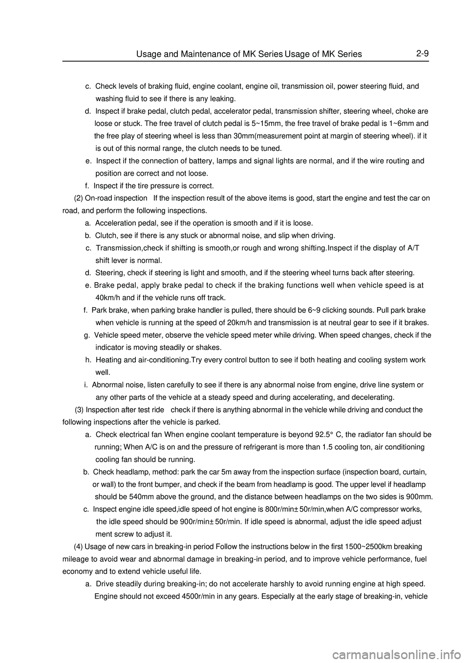
d. Inspect if brake pedal, clutch pedal, accelerator pedal, transmission shifter, steering wheel, choke are
loose or stuck. The free travel of clutch pedal is 5~15mm, the free travel of brake pedal is 1~6mm and
the free play of steering wheel is less than 30mm(measurement point at margin of steering wheel). if it
is out of this normal range, the clutch needs to be tuned.
e. Inspect if the connection of battery, lamps and signal lights are normal, and if the wire routing and
position are correct and not loose.
f. Inspect if the tire pressure is correct.
(2) On-road inspection If the inspection result of the above items is good, start the engine and test the car on
road, and perform the following inspections.
a. Acceleration pedal, see if the operation is smooth and if it is loose.
b. Clutch, see if there is any stuck or abnormal noise, and slip when driving.
c. Transmission,check if shifting is smooth,or rough and wrong shifting.Inspect if the display of A/T
shift lever is normal.
d. Steering, check if steering is light and smooth, and if the steering wheel turns back after steering.
e. Brake pedal, apply brake pedal to check if the braking functions well when vehicle speed is at
40km/h and if the vehicle runs off track.
f. Park brake, when parking brake handler is pulled, there should be 6~9 clicking sounds. Pull park brake
when vehicle is running at the speed of 20km/h and transmission is at neutral gear to see if it brakes.
g. Vehicle speed meter, observe the vehicle speed meter while driving. When speed changes, check if the
indicator is moving steadily or shakes.
h. Heating and air-conditioning.Try every control button to see if both heating and cooling system work
well.
i. Abnormal noise, listen carefully to see if there is any abnormal noise from engine, drive line system or
any other parts of the vehicle at a steady speed and during accelerating, and decelerating.
(3) Inspection after test ride check if there is anything abnormal in the vehicle while driving and conduct the
following inspections after the vehicle is parked.
a. Check electrical fan When engine coolant temperature is beyond 92.5°C, the radiator fan should be
running; When A/C is on and the pressure of refrigerant is more than 1.5 cooling ton, air conditioning
cooling fan should be running.
b. Check headlamp, method: park the car 5m away from the inspection surface (inspection board, curtain,
or wall) to the front bumper, and check if the beam from headlamp is good. The upper level if headlamp
should be 540mm above the ground, and the distance between headlamps on the two sides is 900mm.
c. Inspect engine idle speed,idle speed of hot engine is 800r/min±50r/min,when A/C compressor works,
the idle speed should be 900r/min±50r/min. If idle speed is abnormal, adjust the idle speed adjust
ment screw to adjust it.
(4) Usage of new cars in breaking-in period Follow the instructions below in the first 1500~2500km breaking
mileage to avoid wear and abnormal damage in breaking-in period, and to improve vehicle performance, fuel
economy and to extend vehicle useful life.
a. Drive steadily during breaking-in; do not accelerate harshly to avoid running engine at high speed.
Engine should not exceed 4500r/min in any gears. Especially at the early stage of breaking-in, vehicleUsage and Maintenance of MK Series - Usage of MK Series
Page 36 of 416
2-15
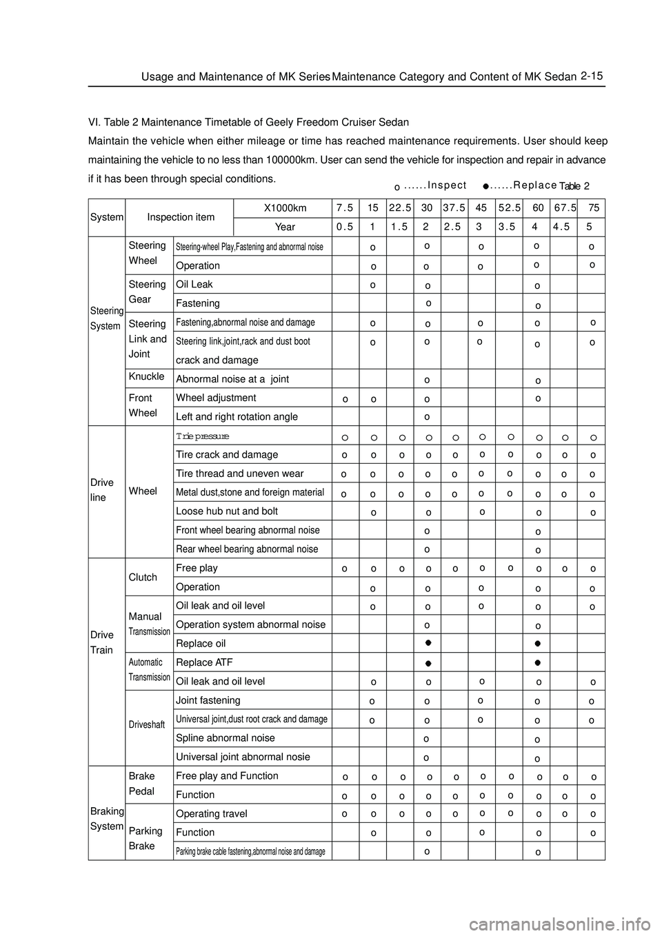
VI. Table 2 Maintenance Timetable of Geely Freedom Cruiser SedanMaintain the vehicle when either mileage or time has reached maintenance requirements. User should keep
maintaining the vehicle to no less than 100000km. User can send the vehicle for inspection and repair in advance
if it has been through special conditions.SystemInspection itemX1000km
Year7.5 15 22.5 30 37.5 45 52.5 60 67.5 75
0.5 1 1.5 2 2.5 3 3.5 4 4.5 5Steering
SystemSteering-wheel Play,Fastening and abnormal noiseOperation
Oil Leak
FasteningFastening,abnormal noise and damage
Steering link,joint,rack and dust bootcrack and damage
Abnormal noise at a joint
Wheel adjustment
Left and right rotation angle
Trie pressure
Tire crack and damage
Tire thread and uneven wearMetal dust,stone and foreign materialLoose hub nut and boltFront wheel bearing abnormal noise
Rear wheel bearing abnormal noiseFree play
Operation
Oil leak and oil level
Operation system abnormal noise
Replace oil
Replace ATF
Oil leak and oil level
Joint fasteningUniversal joint,dust root crack and damageSpline abnormal noise
Universal joint abnormal nosie
Free play and Function
Function
Operating travel
FunctionParking brake cable fastening,abnormal noise and damageo......Inspect ......ReplaceTable 2 Drive
line
Drive
Train
Braking
SystemSteering
Wheel
Steering
Gear
Steering
Link and
Joint
Knuckle
Front
Wheel
Wheel
Clutch
ManualTransmissionAutomaticTransmissionDriveshaftBrake
Pedal
Parking
BrakeUsage and Maintenance of MK Series - Maintenance Category and Content of MK Sedano
o
oo
o o oo o
o o
oo
o o
oo
ooo
o
o oo
o ooo
o o o
o
oo o o o
o o o o
o
oo o o o
o o o o
o
oo o o o
o o o o
o
oo o o o
o o o o
o
oo o o o
o o o o
o
oo o o o
o o o o
o
oo o o o
o o o o
o
oo o o o
o o o o
oo o o
o
o
o o o
o
o
o o o
o
o
o o o
o
o
o o o
o
o
o o o
o
oo o
o o
o o
o o
o o
o oo o o
o
o
Page 47 of 416
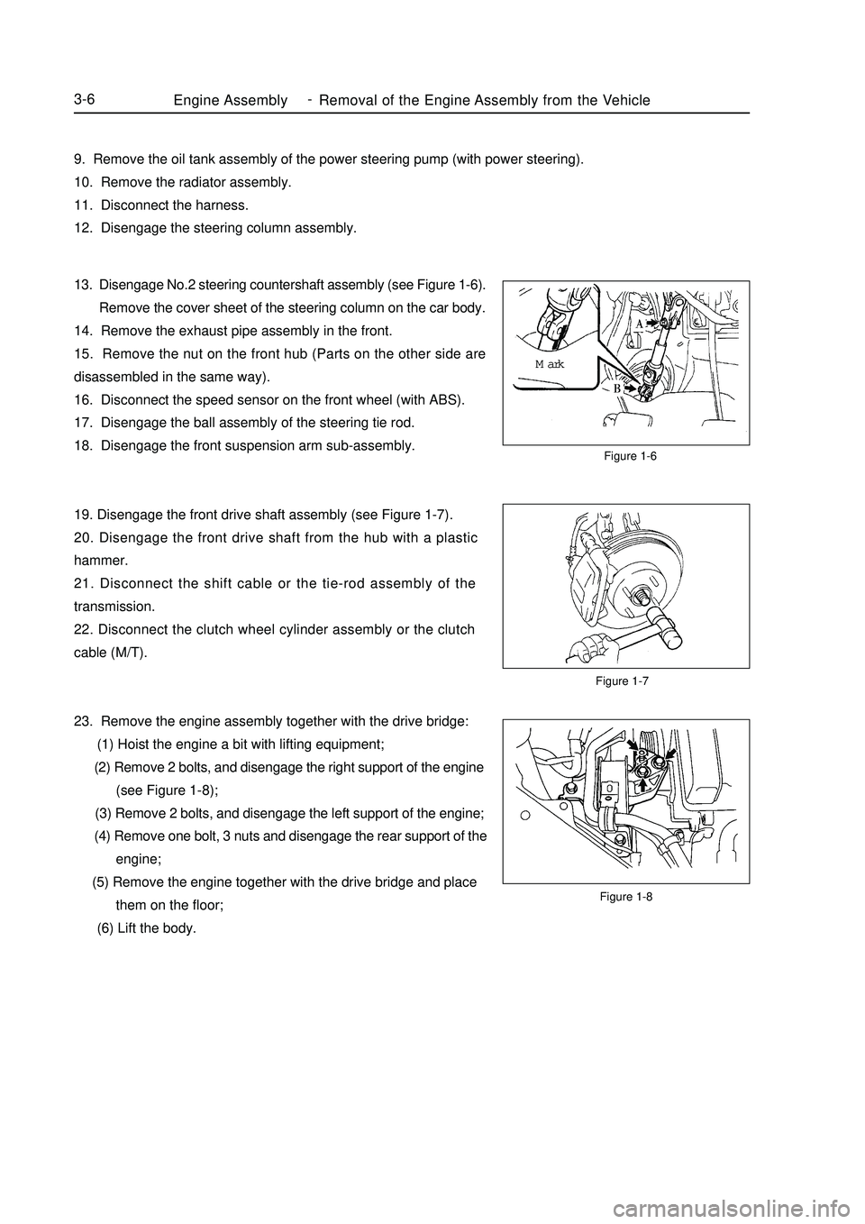
Figure 1-7Figure 1-6
Figure 1-8Engine AssemblyRemoval of the Engine Assembly from the Vehicle3-69. Remove the oil tank assembly of the power steering pump (with power steering).
10. Remove the radiator assembly.
11. Disconnect the harness.
12. Disengage the steering column assembly.
13. Disengage No.2 steering countershaft assembly (see Figure 1-6).
Remove the cover sheet of the steering column on the car body.
14. Remove the exhaust pipe assembly in the front.
15. Remove the nut on the front hub (Parts on the other side are
disassembled in the same way).
16. Disconnect the speed sensor on the front wheel (with ABS).
17. Disengage the ball assembly of the steering tie rod.
18. Disengage the front suspension arm sub-assembly.
19. Disengage the front drive shaft assembly (see Figure 1-7).
20. Disengage the front drive shaft from the hub with a plastic
hammer.
21. Disconnect the shift cable or the tie-rod assembly of the
transmission.
22. Disconnect the clutch wheel cylinder assembly or the clutch
cable (M/T).
23. Remove the engine assembly together with the drive bridge:
(1) Hoist the engine a bit with lifting equipment;
(2) Remove 2 bolts, and disengage the right support of the engine
(see Figure 1-8);
(3) Remove 2 bolts, and disengage the left support of the engine;
(4) Remove one bolt, 3 nuts and disengage the rear support of the
engine;
(5) Remove the engine together with the drive bridge and place
them on the floor;
(6) Lift the body.Mark -
Page 49 of 416

Chapter 2 Engine MechanicalSection 1 Engine ComponentsComponent ViewFigure 2-1Engine MechanicalEngine Components3-8Upside of radiator support
Engine cover lock assembly
Starter assembly
Output pipe of oil cooler
Input pipe of oil coolerTransmission control cable assembly Fuel oil sub-assembly Accelerator control cable assemble
Water inlet pipe of heater
Water outlet pipe of heaterTransmission control cable assemblySuitable for 1.5L/1.6L(Tight coupling)Suitable for 1.3L/1.5L(Non-tight coupling) Radiator assemblyAir filter assembly with hose
Clutch release assembly
Water inlet pipe of radiator
Water outlet pipe of radiator
Battery -
Page 66 of 416
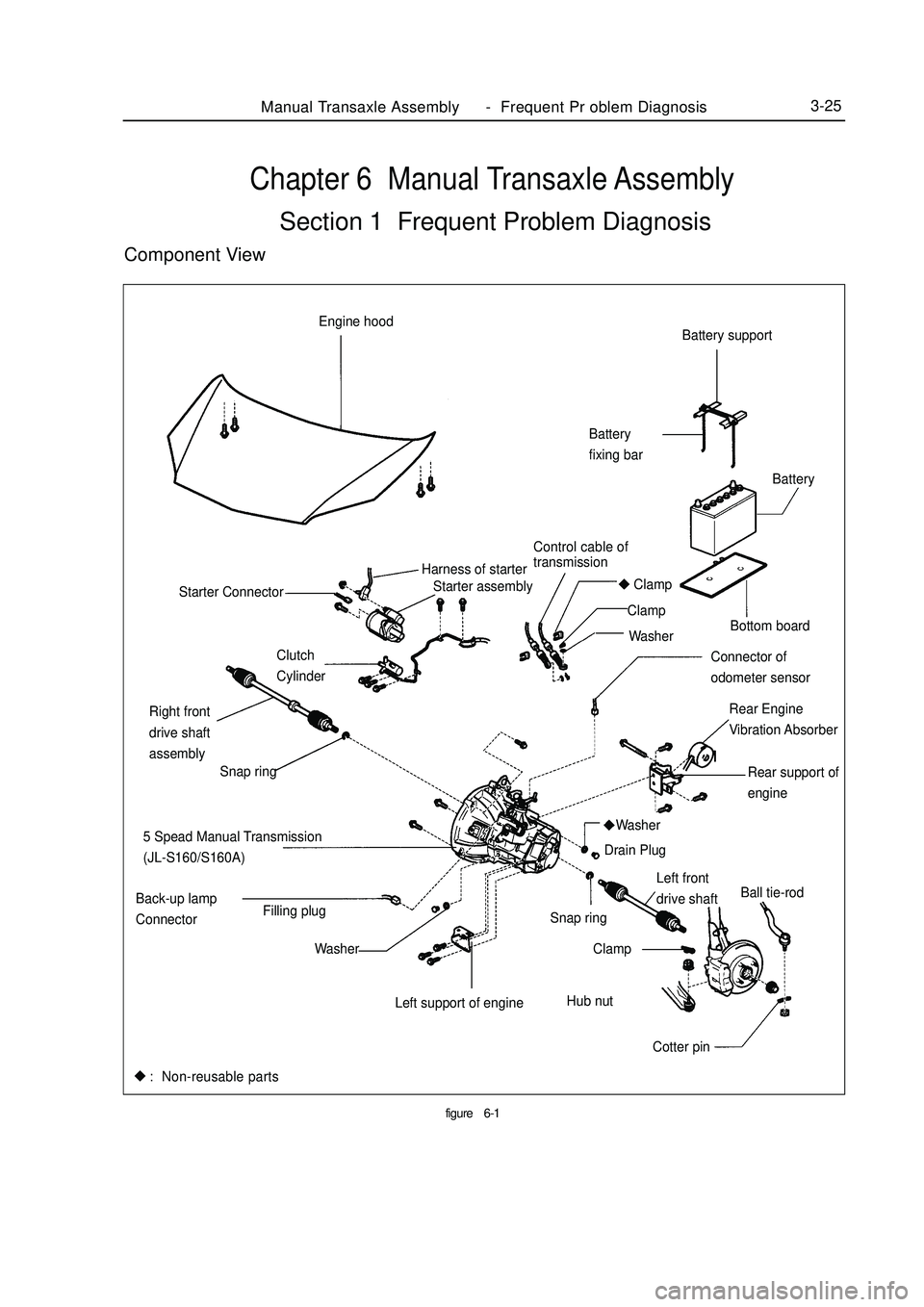
Chapter 6 Manual Transaxle AssemblySection 1 Frequent Problem DiagnosisComponent Viewfigure6-1Manual Transaxle Assembly Frequent Pr oblem Diagnosis3-25Battery support
Battery
fixing bar
Bottom board
Rear Engine
Vibration Absorber Starter assembly Engine hood
Control cable of
transmissionBattery
Harness of starter
Clamp
Clamp
Washer
Connector of
odometer sensor Clutch
Cylinder Starter Connector
Rear support of
engine
5 Spead Manual Transmission
(JL-S160/S160A)
Left front
drive shaftBall tie-rod
Cotter pin Hub nut Snap ring
Clamp
Left support of engineWasher
Washer Back-up lamp
ConnectorFilling plugDrain Plug Right front
drive shaft
assembly
Snap ring: Non-reusable parts -
Page 68 of 416
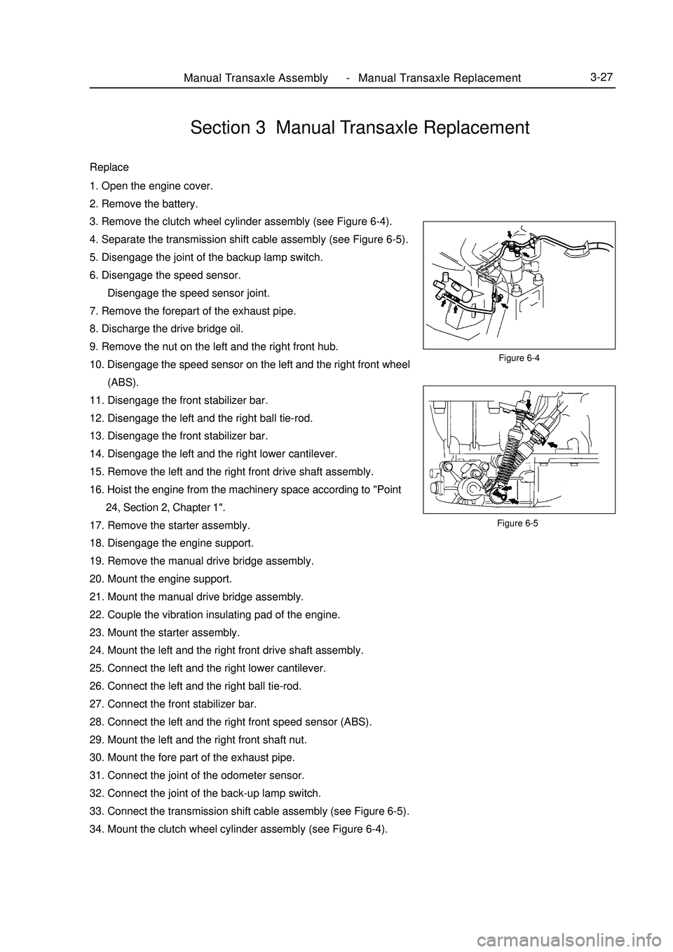
Figure 6-5Manual Transaxle Assembly Manual Transaxle Replacement3-27Section 3 Manual Transaxle ReplacementReplace1. Open the engine cover.
2. Remove the battery.
3. Remove the clutch wheel cylinder assembly (see Figure 6-4).
4. Separate the transmission shift cable assembly (see Figure 6-5).
5. Disengage the joint of the backup lamp switch.
6. Disengage the speed sensor.
Disengage the speed sensor joint.
7. Remove the forepart of the exhaust pipe.
8. Discharge the drive bridge oil.
9. Remove the nut on the left and the right front hub.
10. Disengage the speed sensor on the left and the right front wheel
(ABS).
11. Disengage the front stabilizer bar.
12. Disengage the left and the right ball tie-rod.
13. Disengage the front stabilizer bar.
14. Disengage the left and the right lower cantilever.
15. Remove the left and the right front drive shaft assembly.
16. Hoist the engine from the machinery space according to "Point
24, Section 2, Chapter 1".
17. Remove the starter assembly.
18. Disengage the engine support.
19. Remove the manual drive bridge assembly.
20. Mount the engine support.
21. Mount the manual drive bridge assembly.
22. Couple the vibration insulating pad of the engine.
23. Mount the starter assembly.
24. Mount the left and the right front drive shaft assembly.
25. Connect the left and the right lower cantilever.
26. Connect the left and the right ball tie-rod.
27. Connect the front stabilizer bar.
28. Connect the left and the right front speed sensor (ABS).
29. Mount the left and the right front shaft nut.
30. Mount the fore part of the exhaust pipe.
31. Connect the joint of the odometer sensor.
32. Connect the joint of the back-up lamp switch.
33. Connect the transmission shift cable assembly (see Figure 6-5).
34. Mount the clutch wheel cylinder assembly (see Figure 6-4).Figure 6-4 -
Page 70 of 416
Chapter 7 Automatic Transaxle AssemblySection 1 Frequent Problems DiagnosisPossible Cause1. There is no scan information.
(1)The diagnosis system fails.
(2)The automatic transmission unit fails.
2. The engine can't start.
(1)The engine system fails.
(2)The fuel pump or torque meter fails.
3. The vehicle cant' runs forwards.
(1)The circuit voltage is improper.
(2)The rear clutch or single clutch fails.
(3)The valve fails.
4. The vehicle can't run backwards.
(1)The low speed brake or front clutch pressure is improper.
(2)The front clutch or low speed reverse gear fails.
(3)The valve fails.
5. The vehicle can't runs forwards or backwards.
(1)The pressure deduction is improper or the transmission signal fails.
(2)There is pressure in the oil pump or the valve body fails.
6. The engine stalls in gear shift.
(1)The engine system or clutch torque meter fails.
(2)The valve body or torque meter fails.
7. The vehicle vibrates and lasts for a long time when the gear is shifted from N to D.
(1)The rear clutch fails.
(2)The valve body clutch fails.
(3)The restrictor switch fails.
8. The vehicle vibrates and lasts for a long time when the gear is shifted from N to R.
(1)The front clutch pressure fails.
(2)The front clutch or valve body fails.
(3)The low speed reserve gear pressure or low speed reverse gear fails.
9. The vehicle vibrates and lasts for a long time when the gear is shifted from N to D/R.
(1)The pressure reduction fails.
(2)The oil pump fails.
(3)The valve body fails.
10. The gear shift impacts.
(1)The servo switch or restrictor position switch fails.
(2)The pressure is decreases abnormally.
(3)The clutch or brake fails.
11. All gear shift points are either too early or too late in the running status.Automatic Transaxle Assembly Frequent Problems Diagnosis3-29 -