clutch GEELY MK 2008 Owner's Manual
[x] Cancel search | Manufacturer: GEELY, Model Year: 2008, Model line: MK, Model: GEELY MK 2008Pages: 416, PDF Size: 25.19 MB
Page 170 of 416
Brake System -Vacuum Booster4-93Replacement1. Discharge the brake fluid.
Note:
Never spray the brake fluid on the paint surface, otherwise wash it immediately.
2. Unfix the clutch fluid tank pipe (manual transaxle).
3. Remove the brake master cylinder.
4. Remove the HECU assembly (with ABS).
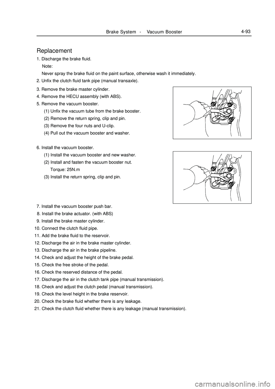
5. Remove the vacuum booster.
(1) Unfix the vacuum tube from the brake booster.
(2) Remove the return spring, clip and pin.
(3) Remove the four nuts and U-clip.
(4) Pull out the vacuum booster and washer.
6. Install the vacuum booster.
(1) Install the vacuum booster and new washer.
(2) Install and fasten the vacuum booster nut.
Torque: 25N.m
(3) Install the return spring, clip and pin.
7. Install the vacuum booster push bar.
8. Install the brake actuator. (with ABS)
9. Install the brake master cylinder.
10. Connect the clutch fluid pipe.
11. Add the brake fluid to the reservoir.
12. Discharge the air in the brake master cylinder.
13. Discharge the air in the brake pipeline.
14. Check and adjust the height of the brake pedal.
15. Check the free stroke of the pedal.
16. Check the reserved distance of the pedal.
17. Discharge the air in the clutch tank pipe (manual transmission).
18. Check and adjust the clutch pedal (manual transmission).
19. Check the level height in the brake reservoir.
20. Check the brake fluid whether there is any leakage.
21. Check the clutch fluid whether there is any leakage (manual transmission).
Page 188 of 416
Part V Electric System & AccessoryChapter 1 Starting and Charging SystemSection 1 Starting System (MR479Q MR479QA MR481QA)I. Starter inspectionNote:
These tests must be completed within 5s, so as to prevent coil from burning out.
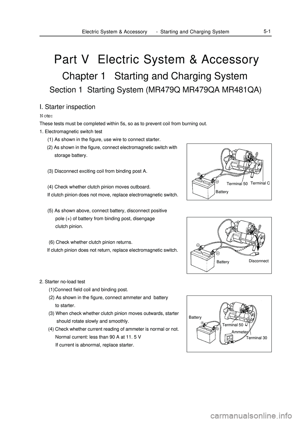
1. Electromagnetic switch testElectric System & Accessory-Starting and Charging System5-1 (1) As shown in the figure, use wire to connect starter.
(2) As shown in the figure, connect electromagnetic switch with
storage battery.
(3) Disconnect exciting coil from binding post A.
(4) Check whether clutch pinion moves outboard.
If clutch pinion does not move, replace electromagnetic switch.
(5) As shown above, connect battery, disconnect positive
pole (+) of battery from binding post, disengage
clutch pinion.
(6) Check whether clutch pinion returns.
If clutch pinion does not return, replace electromagnetic switch.
2. Starter no-load test
(1)Connect field coil and binding post.
(2) As shown in the figure, connect ammeter and battery
to starter.
(3) When check whether clutch pinion moves outwards, starter
should rotate slowly and smoothly.
(4) Check whether current reading of ammeter is normal or not.
Normal current: less than 90 A at 11. 5 V
If current is abnormal, replace starter.Ammeter Battery
Terminal 50
Terminal 30Disconnect
BatteryBatteryTerminal C
Terminal 50
Page 259 of 416
Item
Temperature regulation method
CompressorNominal refrigerating capacity / w
Displacement / (ml /r)
Model
Power consumed by magnetic clutch /W
Lubricating oil / ml
BlowerMaximum air quantity / (m3/h)
Air regulation
Motor power / W
Dimension /mm
Heat exchange quantity / W
Fan motor current / A
Fan motor revolution / (r/min)
Dimension /mm
Refrigerating capacity /W
Thermostatic expansion valve Condenser
Evaporator
Driving belt
Refrigerant filling amount/gChapter 7 Air Conditioning SystemSection 1 General InformationOverview:Air-conditioning system consists of refrigeration and heating parts. Refrigerating system mainly consists of
compressor, condenser and evaporator etc, it adsorbs heat in the air through circulation of refrigerant, so as to
reduce air temperature in car body and eliminate water vapour in air, to achieve the purpose of temperature drop
and dehumidification. Heating system mainly consists of heat exchanger and heater unit. It utilizes heat of engine
cooling water to heat air via heat exchanger, so as to achieve the purpose of heating. Regulation and control of
temperature, humidity and flow rate of air in car body is realized via heating and refrigeration systems separately
or jointly.
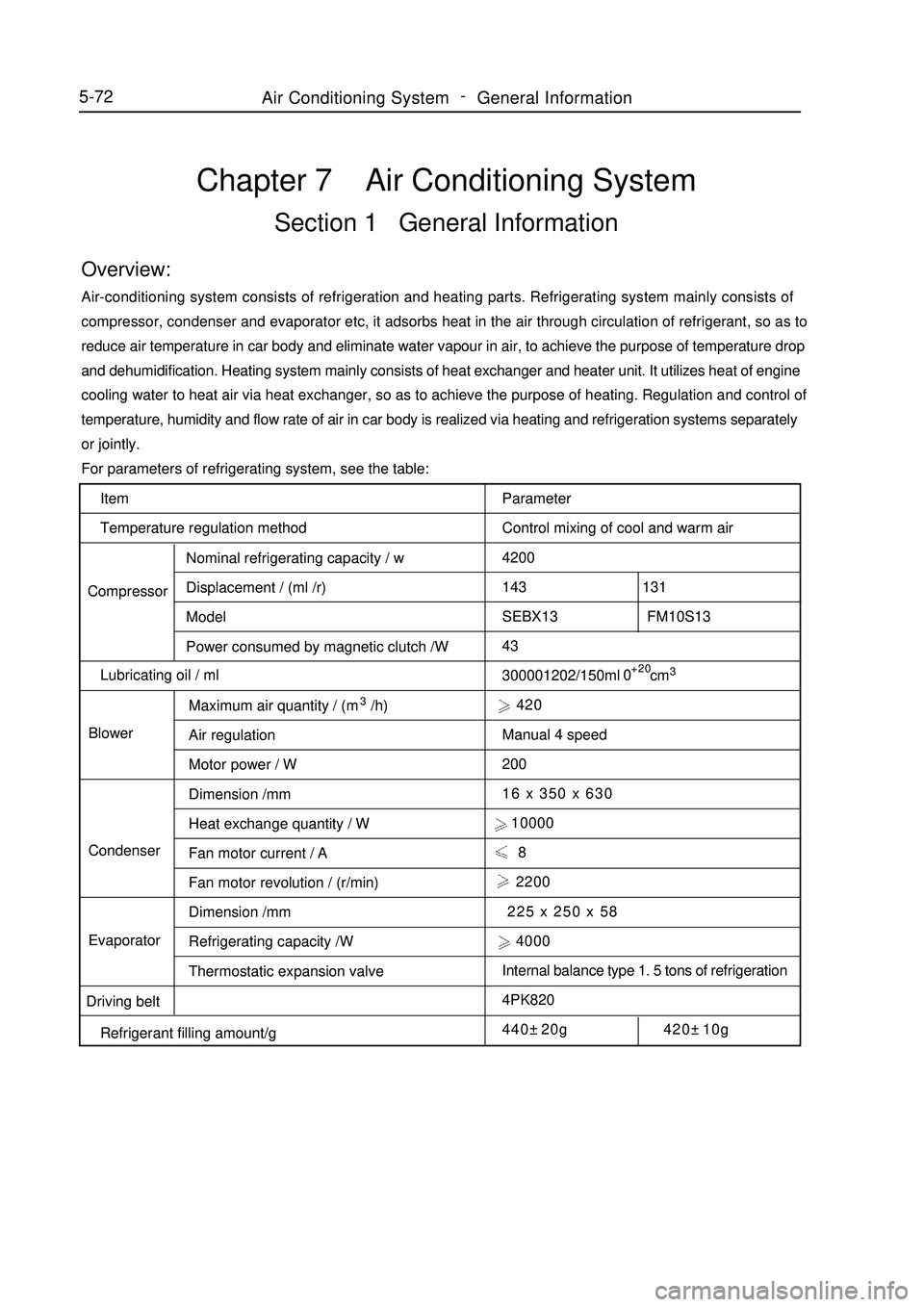
For parameters of refrigerating system, see the table:
Parameter
Control mixing of cool and warm air
4200
143 131
SEBX13 FM10S13
43
300001202/150ml cm3 420
Manual 4 speed
200
16 x 350 x 630
10000
8
2200
225 x 250 x 58
4000
Internal balance type 1. 5 tons of refrigeration
4PK820
440±20g 420±10g+20
05-72Air Conditioning System -
General Information
Page 261 of 416
Air Conditioning System -General Information5-74Symptom
No air temperature control
Compressor does not work
Insufficient refrigeration
No engine idle speed when air conditioning
switch is ON (switch on)
No air input control
No mode control
Condenser fan does not workSuspected Area
1. Engine coolant quantity
2. Air conditioning control mechanism assembly.
1. Refrigerant quantity
2. Compressor fuse
3. Centralized controller fuse
4. Magnetic clutch relay
5. Pressure switch
6. Magnetic clutch assembly
7. Air conditioning compressor assembly
8. Integrated control panel assembly (air conditioner switch)
9. Air conditioner thermistor
10. Engine ECU
11. Wiring harness
1. Refrigerant quantity
2. Refrigerant pressure
3. Driving belt
4. Air conditioner thermistor
5. Integrated control panel assembly (air conditioner switch)
6. Magnetic clutch assembly
7. Air conditioning compressor assembly
8. Condenser
9. Accumulator-drier
10. Expansion valve
11. Evaporator
12. Refrigerant line
13. Pressure switch
14. Air conditioner control mechanism assembly
15. Wiring harness
1. Idle speed control system
2. Wiring harness
3. ECM
1.Air conditioner control mechanism assembly
1.Air conditioner control mechanism assembly
1. MAIN fuse
2. Condenser fan fuse
3. Condenser fan relay
4. Condenser fan motor
5. Wiring harness
Page 262 of 416
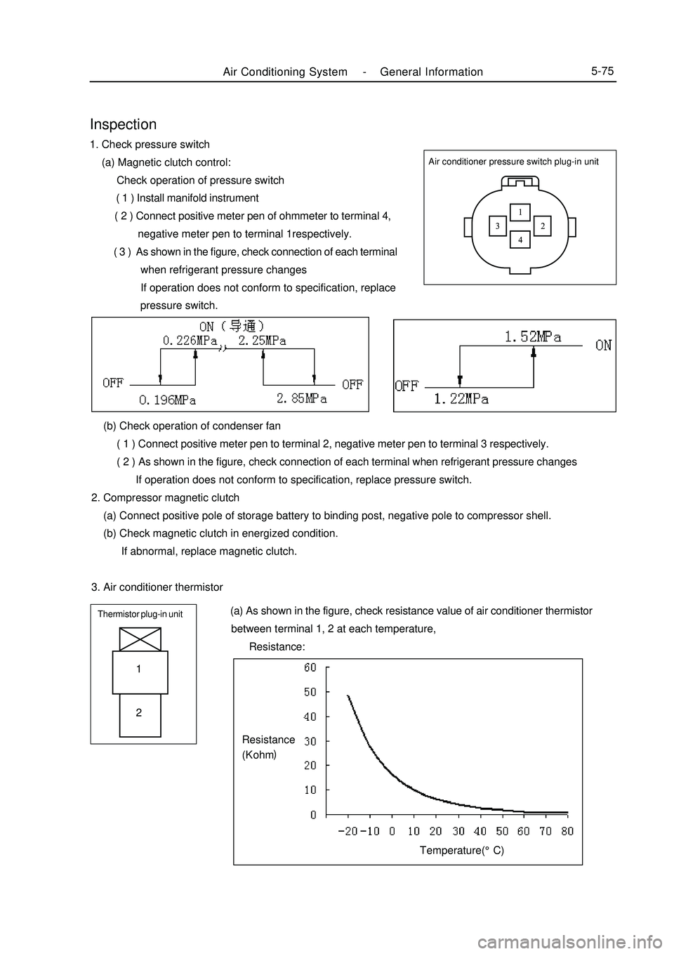
Air Conditioning System -General Information5-75Air conditioner pressure switch plug-in unitInspection1. Check pressure switch
(a) Magnetic clutch control:
Check operation of pressure switch
( 1 ) Install manifold instrument
( 2 ) Connect positive meter pen of ohmmeter to terminal 4,
negative meter pen to terminal 1respectively.
( 3 ) As shown in the figure, check connection of each terminal
when refrigerant pressure changes
If operation does not conform to specification, replace
pressure switch.
(b) Check operation of condenser fan
( 1 ) Connect positive meter pen to terminal 2, negative meter pen to terminal 3 respectively.
( 2 ) As shown in the figure, check connection of each terminal when refrigerant pressure changes
If operation does not conform to specification, replace pressure switch.
2. Compressor magnetic clutch
(a) Connect positive pole of storage battery to binding post, negative pole to compressor shell.
(b) Check magnetic clutch in energized condition.
If abnormal, replace magnetic clutch.
3. Air conditioner thermistorThermistor plug-in unit (a) As shown in the figure, check resistance value of air conditioner thermistor
between terminal 1, 2 at each temperature,
Resistance:1
2Temperature(°C)Resistance
(K ohm)
Page 264 of 416
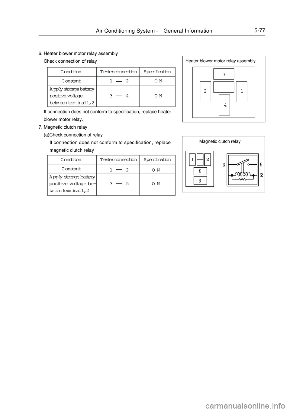
5-776. Heater blower motor relay assembly
Check connection of relayHeater blower motor relay assembly3
21
4 If connection does not conform to specification, replace heater
blower motor relay.
7. Magnetic clutch relay
(a)Check connection of relay
If connection does not conform to specification, replace
magnetic clutch relayCondition Tester connection Specification
Constant1 2 ON
3 4 ON Apply storage battery
positive voltage
between terminal 1, 2Condition Tester connection Specification
Constant
1 2 ON
3 5 ON Apply storage battery
positive voltage be-
tween terminal 1, 2Magnetic clutch relayAir Conditioning System -General Information
Page 282 of 416
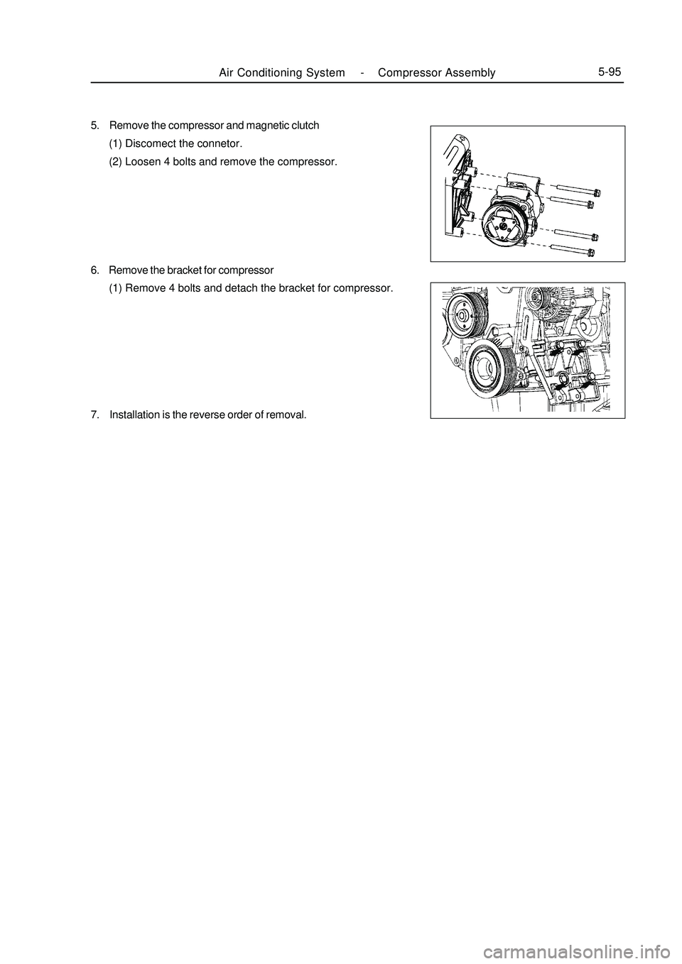
5. Remove the compressor and magnetic clutch
(1) Discomect the connetor.
(2) Loosen 4 bolts and remove the compressor.
6. Remove the bracket for compressor
(1) Remove 4 bolts and detach the bracket for compressor.
7. Installation is the reverse order of removal.Air Conditioning System -Compressor Assembly5-95
Page 368 of 416
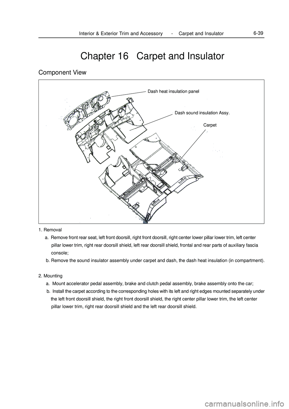
Chapter 16 Carpet and InsulatorComponent ViewCarpet Dash sound insulation Assy. Dash heat insulation panelInterior & Exterior Trim and Accessory -Carpet and Insulator6-391. Removal
a. Remove front rear seat, left front doorsill, right front doorsill, right center lower pillar lower trim, left center
pillar lower trim, right rear doorsill shield, left rear doorsill shield, frontal and rear parts of auxiliary fascia
console;
b. Remove the sound insulator assembly under carpet and dash, the dash heat insulation (in compartment).
2. Mounting
a. Mount accelerator pedal assembly, brake and clutch pedal assembly, brake assembly onto the car;
b. Install the carpet according to the corresponding holes with its left and right edges mounted separately under
the left front doorsill shield, the right front doorsill shield, the right center pillar lower trim, the left center
pillar lower trim, right rear doorsill shield and the left rear doorsill shield.
Page 375 of 416
It is mainly used to install the pipes and accessories of the brake system and clutch system.
5. Front wall upper assembly
The front wall upper assembly includes left/right hinge base mounting plate big assembly, front wall upper
front cover big assembly, VIN number mounting plate, and front wall upper rear cover big assembly etc.
It forms a high-stiffness frame structure together with the engine compartment assembly and the front wall
lower plate assembly. It can generate strong resistant to the transverse collision and rolling deformation. It can also
separate the engine compartment form the cabin, preventing the odor entering into the cabin. Consequently, it can
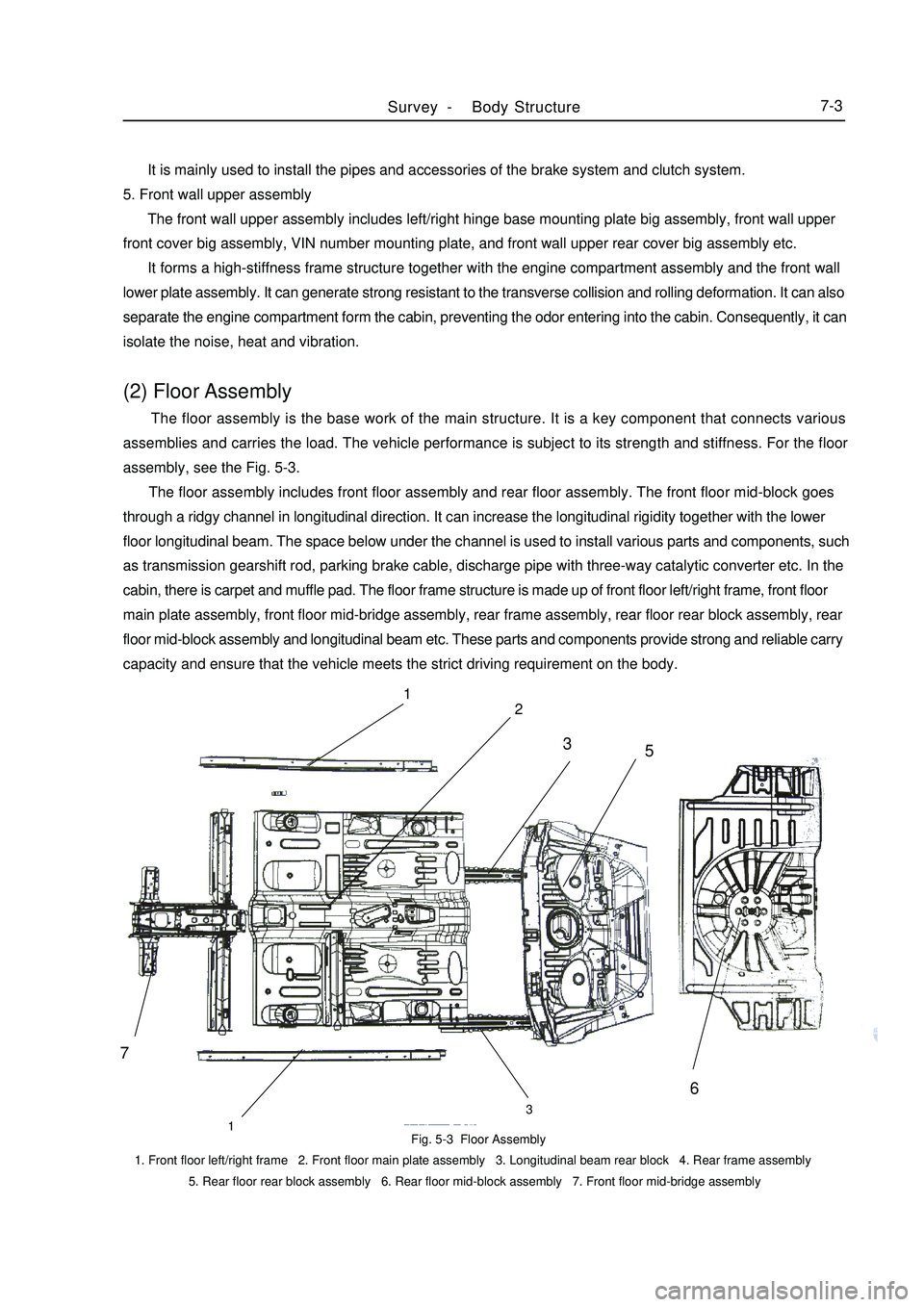
isolate the noise, heat and vibration.(2) Floor Assembly The floor assembly is the base work of the main structure. It is a key component that connects various
assemblies and carries the load. The vehicle performance is subject to its strength and stiffness. For the floor
assembly, see the Fig. 5-3.
The floor assembly includes front floor assembly and rear floor assembly. The front floor mid-block goes
through a ridgy channel in longitudinal direction. It can increase the longitudinal rigidity together with the lower
floor longitudinal beam. The space below under the channel is used to install various parts and components, such
as transmission gearshift rod, parking brake cable, discharge pipe with three-way catalytic converter etc. In the
cabin, there is carpet and muffle pad. The floor frame structure is made up of front floor left/right frame, front floor
main plate assembly, front floor mid-bridge assembly, rear frame assembly, rear floor rear block assembly, rear
floor mid-block assembly and longitudinal beam etc. These parts and components provide strong and reliable carry
capacity and ensure that the vehicle meets the strict driving requirement on the body.Fig. 5-3 Floor Assembly
1. Front floor left/right frame 2. Front floor main plate assembly 3. Longitudinal beam rear block 4. Rear frame assembly
5. Rear floor rear block assembly 6. Rear floor mid-block assembly 7. Front floor mid-bridge assemblySurvey -Body Structure7-371
2
133
5
6
Page 413 of 416
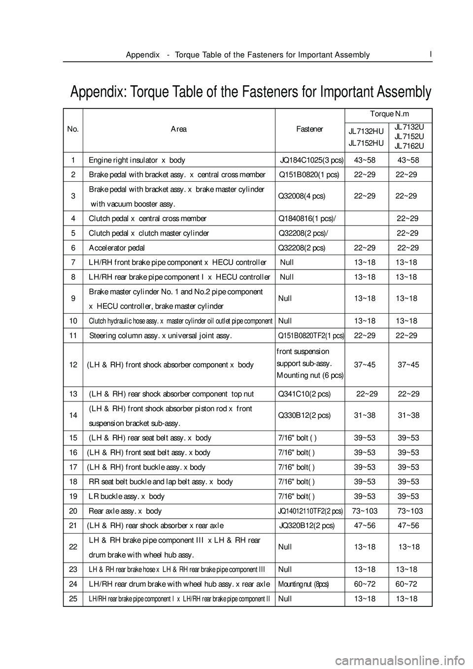
1 Engine right insulator x body JQ184C1025(3 pcs)43~58 43~58
2 Brake pedal with bracket assy. x central cross member Q151B0820(1 pcs)22~29 22~29
3Brake pedal with bracket assy. x brake master cylinder
Q32008(4 pcs)22~29 22~29
with vacuum booster assy.
4 Clutch pedal x central cross member Q1840816(1 pcs)/22~29
5 Clutch pedal x clutch master cylinder Q32208(2 pcs)/22~29
6 Accelerator pedal Q32208(2 pcs)22~29 22~29
7 LH/RH front brake pipe component x HECU controller Null13~18 13~18
8 LH/RH rear brake pipe component I x HECU controller Null13~18 13~18
9Brake master cylinder No. 1 and No.2 pipe component
Null13~18 13~18
x HECU controller, brake master cylinder
10Clutch hydraulic hose assy. x master cylinder oil outlet pipe componentNull13~18 13~18
11 Steering column assy. x universal joint assy.Q151B0820TF2(1 pcs)22~29 22~29
12 (LH & RH) front shock absorber component x body37~45 37~45
13 (LH & RH) rear shock absorber component top nut Q341C10(2 pcs) 22~29 22~29
14(LH & RH) front shock absorber piston rod x front
Q330B12(2 pcs)31~38 31~38
suspension bracket sub-assy.
15 (LH & RH) rear seat belt assy. x body7/16" bolt ( )39~53 39~53
16 (LH & RH) front seat belt assy. x body7/16" bolt( )39~53 39~53
17 (LH & RH) front buckle assy. x body7/16" bolt( )39~53 39~53
18 RR seat belt buckle and lap belt assy. x body7/16" bolt( )39~53 39~53
19 LR buckle assy. x body7/16" bolt( )39~53 39~53
20 Rear axle assy. x bodyJQ14012110TF2(2 pcs)73~103 73~103
21 (LH & RH) rear shock absorber x rear axle JQ320B12(2 pcs)47~56 47~56
22LH & RH brake pipe component III x LH & RH rear
Null13~18 13~18
drum brake with wheel hub assy.
23LH & RH rear brake hose x LH & RH rear brake pipe component IIINull13~18 13~18
24 LH/RH rear drum brake with wheel hub assy. x rear axleMounting nut (8pcs)60~72 60~72
25LH/RH rear brake pipe component I x LH/RH rear brake pipe component IINull13~18 13~18Appendix: Torque Table of the Fasteners for Important AssemblyTorque N.m
No.
JL7132HU
JL7152HUJL7132U
JL7152U
JL7162UAppendix-Torque Table of the Fasteners for Important AssemblyIArea Fastener
front suspension
support sub-assy.
Mounting nut (6 pcs)