height GEELY MK 2008 User Guide
[x] Cancel search | Manufacturer: GEELY, Model Year: 2008, Model line: MK, Model: GEELY MK 2008Pages: 416, PDF Size: 25.19 MB
Page 160 of 416
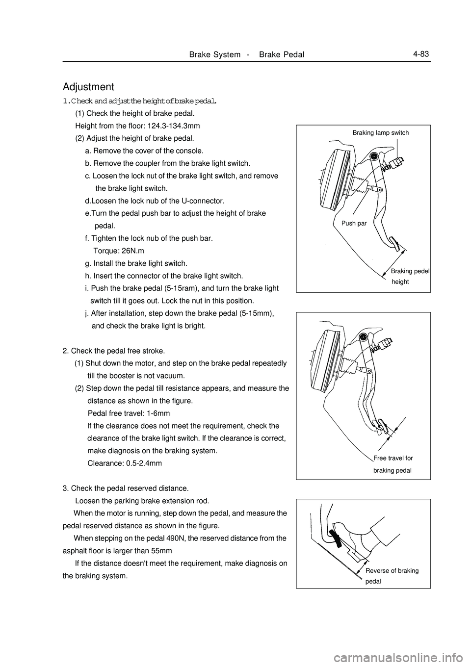
Adjustment1. Check and adjust the height of brake pedal.
(1) Check the height of brake pedal.
Height from the floor: 124.3-134.3mm
(2) Adjust the height of brake pedal.
a. Remove the cover of the console.
b. Remove the coupler from the brake light switch.
c. Loosen the lock nut of the brake light switch, and remove
the brake light switch.
d.Loosen the lock nub of the U-connector.
e.Turn the pedal push bar to adjust the height of brake
pedal.
f. Tighten the lock nub of the push bar.
Torque: 26N.m
g. Install the brake light switch.
h. Insert the connector of the brake light switch.
i. Push the brake pedal (5-15ram), and turn the brake light
switch till it goes out. Lock the nut in this position.
j. After installation, step down the brake pedal (5-15mm),
and check the brake light is bright.
2. Check the pedal free stroke.
(1) Shut down the motor, and step on the brake pedal repeatedly
till the booster is not vacuum.
(2) Step down the pedal till resistance appears, and measure the
distance as shown in the figure.
Pedal free travel: 1-6mm
If the clearance does not meet the requirement, check the
clearance of the brake light switch. If the clearance is correct,
make diagnosis on the braking system.
Clearance: 0.5-2.4mm
3. Check the pedal reserved distance.
Loosen the parking brake extension rod.
When the motor is running, step down the pedal, and measure the
pedal reserved distance as shown in the figure.
When stepping on the pedal 490N, the reserved distance from the
asphalt floor is larger than 55mm
If the distance doesn't meet the requirement, make diagnosis on
the braking system.Brake System -Brake Pedal4-83Braking lamp switch
Push parBraking pedel
heightFree travel for
braking pedalReverse of braking
pedal
Page 161 of 416
1
2
3Brake System -Brake Pedal4-84Removal After the installation, check and adjust the height, free stroke and reserved distance of the brake pedal.
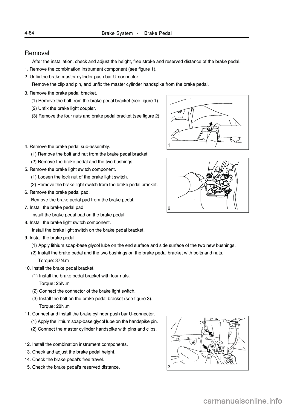
1. Remove the combination instrument component (see figure 1).
2. Unfix the brake master cylinder push bar U-connector.
Remove the clip and pin, and unfix the master cylinder handspike from the brake pedal.
3. Remove the brake pedal bracket.
(1) Remove the bolt from the brake pedal bracket (see figure 1).
(2) Unfix the brake light coupler.
(3) Remove the four nuts and brake pedal bracket (see figure 2).
4. Remove the brake pedal sub-assembly.
(1) Remove the bolt and nut from the brake pedal bracket.
(2) Remove the brake pedal and the two bushings.
5. Remove the brake light switch component.
(1) Loosen the lock nut of the brake light switch.
(2) Remove the brake light switch from the brake pedal bracket.
6. Remove the brake pedal pad.
Remove the brake pedal pad from the brake pedal.
7. Install the brake pedal pad.
Install the brake pedal pad on the brake pedal.
8. Install the brake light switch component.
Install the brake light switch on the brake pedal bracket.
9. Install the brake pedal.
(1) Apply lithium soap-base glycol lube on the end surface and side surface of the two new bushings.
(2) Install the brake pedal and the two bushings on the brake pedal bracket with bolts and nuts.
Torque: 37N.m
10. Install the brake pedal bracket.
(1) Install the brake pedal bracket with four nuts.
Torque: 25N.m
(2) Connect the connector of the brake light switch.
(3) Install the bolt on the brake pedal bracket (see figure 3).
Torque: 20N.m
11. Connect and install the brake cylinder push bar U-connector.
(1) Apply the lithium soap-base glycol lube on the handspike pin.
(2) Connect the master cylinder handspike with pins and clips.
12. Install the combination instrument components.
13. Check and adjust the brake pedal height.
14. Check the brake pedal's free travel.
15. Check the brake pedal's reserved distance.
Page 167 of 416
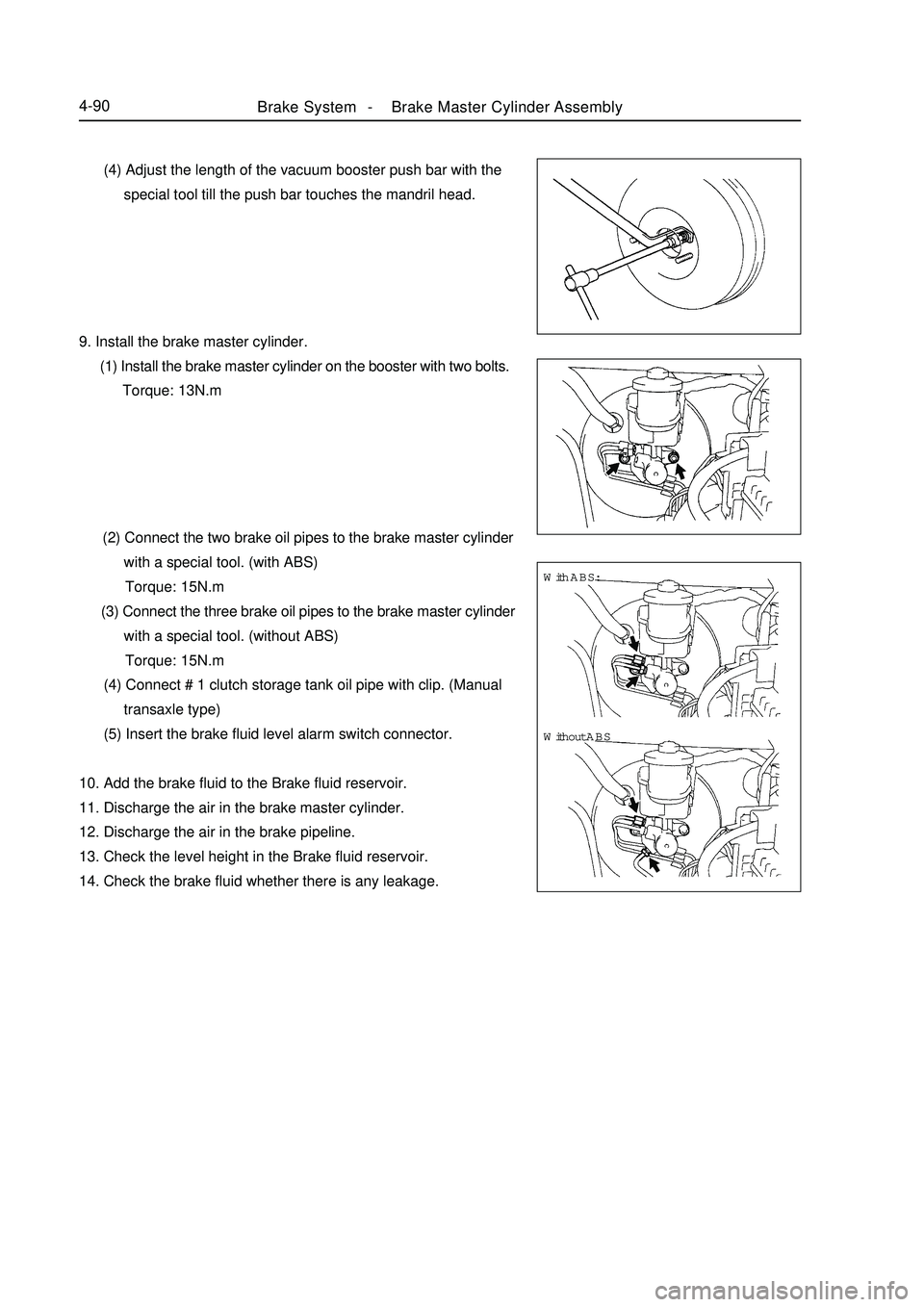
Brake System -Brake Master Cylinder Assembly4-90 (4) Adjust the length of the vacuum booster push bar with the
special tool till the push bar touches the mandril head.
9. Install the brake master cylinder.
(1) Install the brake master cylinder on the booster with two bolts.
Torque: 13N.m
(2) Connect the two brake oil pipes to the brake master cylinder
with a special tool. (with ABS)
Torque: 15N.m
(3) Connect the three brake oil pipes to the brake master cylinder
with a special tool. (without ABS)
Torque: 15N.m
(4) Connect # 1 clutch storage tank oil pipe with clip. (Manual
transaxle type)
(5) Insert the brake fluid level alarm switch connector.
10. Add the brake fluid to the Brake fluid reservoir.
11. Discharge the air in the brake master cylinder.
12. Discharge the air in the brake pipeline.
13. Check the level height in the Brake fluid reservoir.
14. Check the brake fluid whether there is any leakage.With ABS:
Without ABS
Page 170 of 416
Brake System -Vacuum Booster4-93Replacement1. Discharge the brake fluid.
Note:
Never spray the brake fluid on the paint surface, otherwise wash it immediately.
2. Unfix the clutch fluid tank pipe (manual transaxle).
3. Remove the brake master cylinder.
4. Remove the HECU assembly (with ABS).
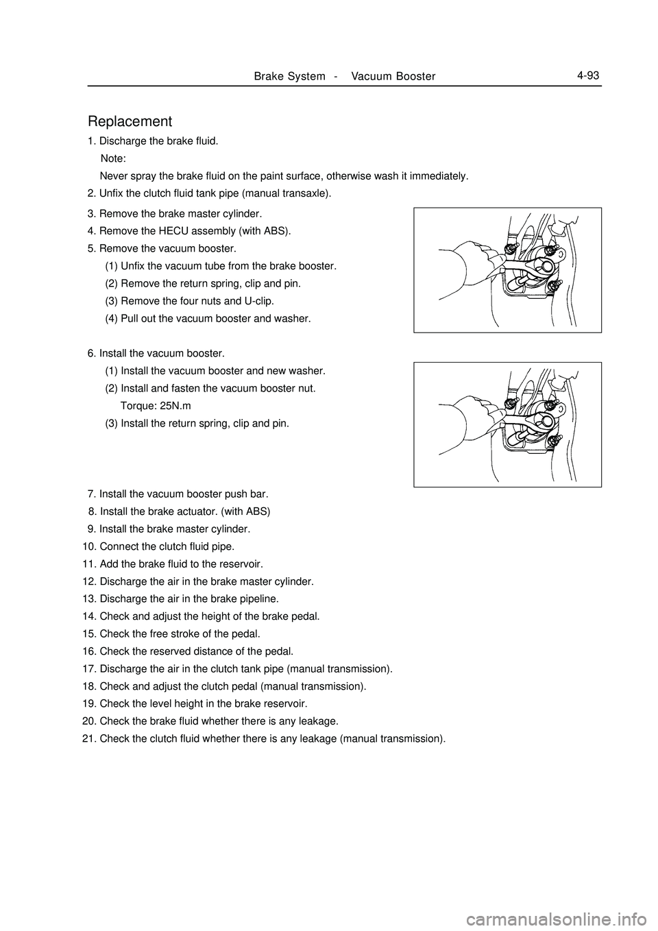
5. Remove the vacuum booster.
(1) Unfix the vacuum tube from the brake booster.
(2) Remove the return spring, clip and pin.
(3) Remove the four nuts and U-clip.
(4) Pull out the vacuum booster and washer.
6. Install the vacuum booster.
(1) Install the vacuum booster and new washer.
(2) Install and fasten the vacuum booster nut.
Torque: 25N.m
(3) Install the return spring, clip and pin.
7. Install the vacuum booster push bar.
8. Install the brake actuator. (with ABS)
9. Install the brake master cylinder.
10. Connect the clutch fluid pipe.
11. Add the brake fluid to the reservoir.
12. Discharge the air in the brake master cylinder.
13. Discharge the air in the brake pipeline.
14. Check and adjust the height of the brake pedal.
15. Check the free stroke of the pedal.
16. Check the reserved distance of the pedal.
17. Discharge the air in the clutch tank pipe (manual transmission).
18. Check and adjust the clutch pedal (manual transmission).
19. Check the level height in the brake reservoir.
20. Check the brake fluid whether there is any leakage.
21. Check the clutch fluid whether there is any leakage (manual transmission).
Page 175 of 416
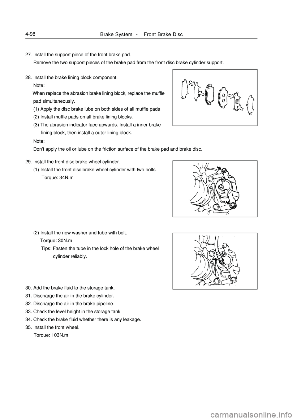
Brake System -Front Brake Disc4-9827. Install the support piece of the front brake pad.
Remove the two support pieces of the brake pad from the front disc brake cylinder support.
28. Install the brake lining block component.
Note:
When replace the abrasion brake lining block, replace the muffle
pad simultaneously.
(1) Apply the disc brake lube on both sides of all muffle pads
(2) Install muffle pads on all brake lining blocks.
(3) The abrasion indicator face upwards. Install a inner brake
lining block, then install a outer lining block.
Note:
Don't apply the oil or lube on the friction surface of the brake pad and brake disc.
29. Install the front disc brake wheel cylinder.
(1) Install the front disc brake wheel cylinder with two bolts.
Torque: 34N.m
(2) Install the new washer and tube with bolt.
Torque: 30N.m
Tips: Fasten the tube in the lock hole of the brake wheel
cylinder reliably.
30. Add the brake fluid to the storage tank.
31. Discharge the air in the brake cylinder.
32. Discharge the air in the brake pipeline.
33. Check the level height in the storage tank.
34. Check the brake fluid whether there is any leakage.
35. Install the front wheel.
Torque: 103N.m
Page 182 of 416
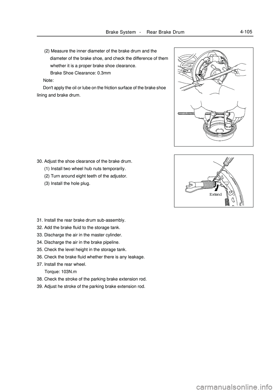
Brake System -Rear Brake Drum4-105 (2) Measure the inner diameter of the brake drum and the
diameter of the brake shoe, and check the difference of them
whether it is a proper brake shoe clearance.
Brake Shoe Clearance: 0.3mm
Note:
Don't apply the oil or lube on the friction surface of the brake shoe
lining and brake drum.
30. Adjust the shoe clearance of the brake drum.
(1) Install two wheel hub nuts temporarily.
(2) Turn around eight teeth of the adjustor.
(3) Install the hole plug.
31. Install the rear brake drum sub-assembly.
32. Add the brake fluid to the storage tank.
33. Discharge the air in the master cylinder.
34. Discharge the air in the brake pipeline.
35. Check the level height in the storage tank.
36. Check the brake fluid whether there is any leakage.
37. Install the rear wheel.
Torque: 103N.m
38. Check the stroke of the parking brake extension rod.
39. Adjust he stroke of the parking brake extension rod.Extend
Page 202 of 416
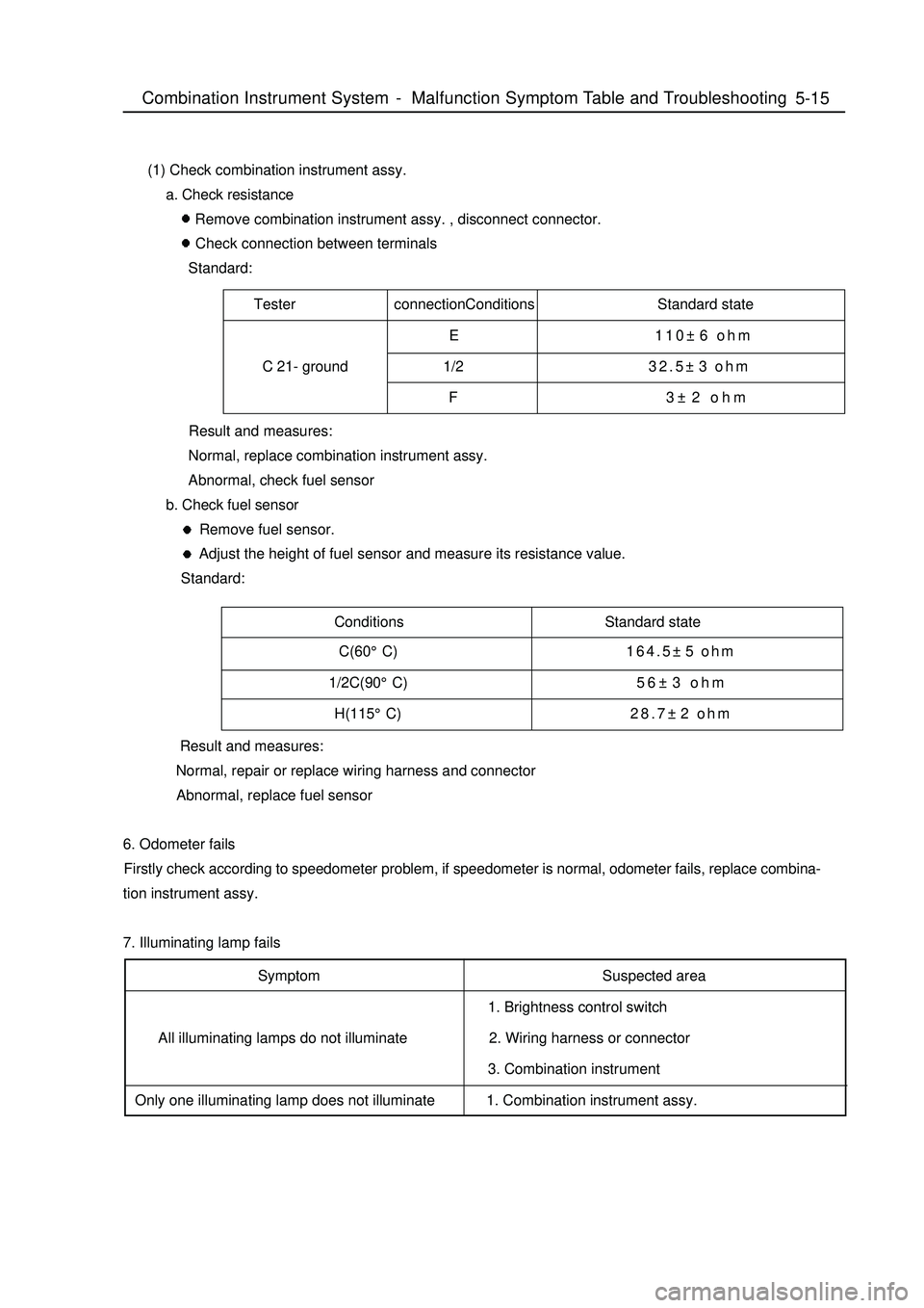
Tester connectionConditions Standard state
E 110±6 ohm
C 21- ground 1/232.5±3 ohm
F 3±2 ohmConditions Standard state5-15 (1) Check combination instrument assy.
a. Check resistance
Remove combination instrument assy. , disconnect connector.
Check connection between terminals
Standard:
Result and measures:
Normal, replace combination instrument assy.
Abnormal, check fuel sensor
b. Check fuel sensor
Remove fuel sensor.
Adjust the height of fuel sensor and measure its resistance value.
Standard:
Result and measures:
Normal, repair or replace wiring harness and connector
Abnormal, replace fuel sensor
6. Odometer fails
Firstly check according to speedometer problem, if speedometer is normal, odometer fails, replace combina-
tion instrument assy.
7. Illuminating lamp fails
Symptom
All illuminating lamps do not illuminate
Only one illuminating lamp does not illuminateSuspected area
1. Brightness control switch
2. Wiring harness or connector
3. Combination instrument
1. Combination instrument assy.Combination Instrument System -Malfunction Symptom Table and Troubleshooting C(60°C)164.5±5 ohm
1/2C(90°C)56±3 ohm
H(115°C)28.7±2 ohm
Page 212 of 416
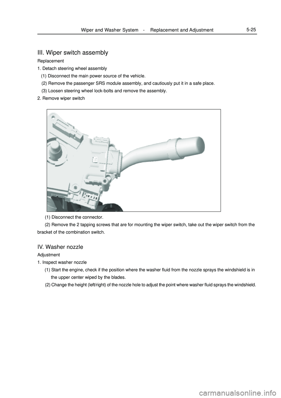
III. Wiper switch assemblyReplacement
1. Detach steering wheel assembly
(1) Disconnect the main power source of the vehicle.
(2) Remove the passenger SRS module assembly, and cautiously put it in a safe place.
(3) Loosen steering wheel lock-bolts and remove the assembly.
2. Remove wiper switch (1) Disconnect the connector.
(2) Remove the 2 tapping screws that are for mounting the wiper switch, take out the wiper switch from the
bracket of the combination switch.IV. Washer nozzleAdjustment
1. Inspect washer nozzle
(1) Start the engine, check if the position where the washer fluid from the nozzle sprays the windshield is in
the upper center wiped by the blades.
(2) Change the height (left/right) of the nozzle hole to adjust the point where washer fluid sprays the windshield.Wiper and Washer System -Replacement and Adjustment5-25
Page 378 of 416
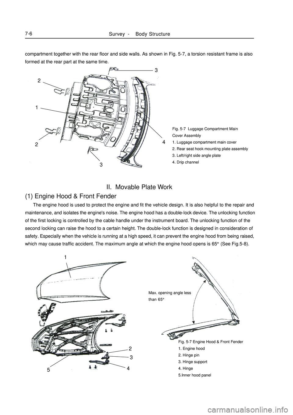
Fig. 5-7 Luggage Compartment Main
Cover Assembly
1. Luggage compartment main cover
2. Rear seat hook mounting plate assembly
3. Left/right side angle plate
4. Drip channelII. Movable Plate Work(1) Engine Hood & Front Fender The engine hood is used to protect the engine and fit the vehicle design. It is also helpful to the repair and
maintenance, and isolates the engine's noise. The engine hood has a double-lock device. The unlocking function
of the first locking is controlled by the cable handle under the instrument board. The unlocking function of the
second locking can raise the hood to a certain height. The double-lock function is designed in consideration of
safety. Especially when the vehicle is running at a high speed, it can prevent the engine hood from being raised,
which may cause traffic accident. The maximum angle at which the engine hood opens is 65°(See Fig.5-8).Fig. 5-7 Engine Hood & Front Fender
1. Engine hood
2. Hinge pin
3. Hinge support
4. Hinge
5.Inner hood panelSurvey -Body Structure7-642
3
51Max. opening angle less
than 65°compartment together with the rear floor and side walls. As shown in Fig. 5-7, a torsion resistant frame is also
formed at the rear part at the same time.3
4
213 2
Page 391 of 416
(f). Flatten the edge with hammer or sizing block, and remove the burr with file to make sure that it is aligned
with the both side alternative plates with a clearance not more than 1mm;
(g). Replace the plate, and clamp it with pincers. Carry out the spot welding along the seam at a space of
approximately 50mm;
(h). Make the welding from the center to both sides alternately block by block. Which can reduce the
deformation;
(i). Strike the welding line with the hammer or sizing block to remove the retaining stress. Polish the welding
lien wit the file or manual grinding wheel to make it even and smooth for the painting.
c. Repair for Accidented Damage
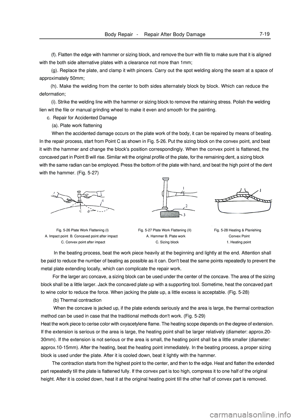
(a). Plate work flattening
When the accidented damage occurs on the plate work of the body, it can be repaired by means of beating.
In the repair process, start from Point C as shown in Fig. 5-26. Put the sizing block on the convex point, and beat
it with the hammer and change the block's position correspondingly. When the convex point is flattened, the
concaved part in Point B will rise. Similar wit the original profile of the plate, for the remaining dent, a sizing block
with the same radian can be employed. Press the bottom of the plate with hand, and beat the high point of the dent
with the hammer. (Fig. 5-27)Fig. 5-27 Plate Work Flattening (II)
A. Hammer B. Plate work
C. Sizing block Fig. 5-26 Plate Work Flattening (I)
A. Impact point B. Concaved point after impact
C. Convex point after impactFig. 5-28 Heating & Planishing
Convex Point
1. Heating pointBody Repair -Repair After Body Damage7-19 In the beating process, beat the work piece heavily at the beginning and lightly at the end. Attention shall
be paid to reduce the number of beating as possible as it can. Don't beat the same points repeatedly to prevent the
metal plate extending locally, which can complicate the repair work.
For the larger arc concave, a sizing block can be used under the center of the concave. The area of the sizing
block shall be a little larger. Jack the concaved plate up with a supporting tool. Sometime, heat the concaved part
to wine color to reduce the force. When jacking the plate up, a little excess is acceptable. (Fig. 5-28)
(b) Thermal contraction
When the concave is jacked up, if the plate extends seriously and the area is large, the thermal contraction
method can be used in case that the traditional methods don't work. (Fig. 5-29)
Heat the work piece to cerise color with oxyacetylene flame. The heating scope depends on the degree of extension.
If the extension is serious or the area is large, the heating point shall be larger relatively (diameter: approx.20-
30mm). If the extension is not serious or the area is small, the heating point shall be a little smaller (diameter:
approx.10-15mm). After the heating, beat the heating point immediately. In the beating process, a proper sizing
block is used under the plate. After it is cooled down, beat it lightly with the hammer.
The contraction starts from the highest point to the center, and then to the edge. Heat and flatten the extended
part repeatedly till the plate is flattened fully. If the convex part is too high, compress it to one half of the original
height. After it is cooled down, heat it at the original heating point till the other half of convex part is removed.