tire pressure GEELY MK 2008 User Guide
[x] Cancel search | Manufacturer: GEELY, Model Year: 2008, Model line: MK, Model: GEELY MK 2008Pages: 416, PDF Size: 25.19 MB
Page 157 of 416

Brake System -Brake System4-80Symptom
Brake Deviation
Noise from brakeSuspected Area
1. Wheel cylinder piston (stuck)
2. Brake shoe lining (oily)
3. Disc (scratched)
4. Brake shoes or lining (cracked or distorted)
5. Wheel hub bearing (worn or damaged)
6. Tire pressure (not as specified)
1. Brake shoe lining (damaged)
2. Installation bolt (loose)
3. Disc (scratched)
4. Brake shoe (bad in quality)
5. Brake shoes lining (oily)
6. Sound isolating shim damaged
7. Hold spring of brake shoe (damage)
Page 205 of 416

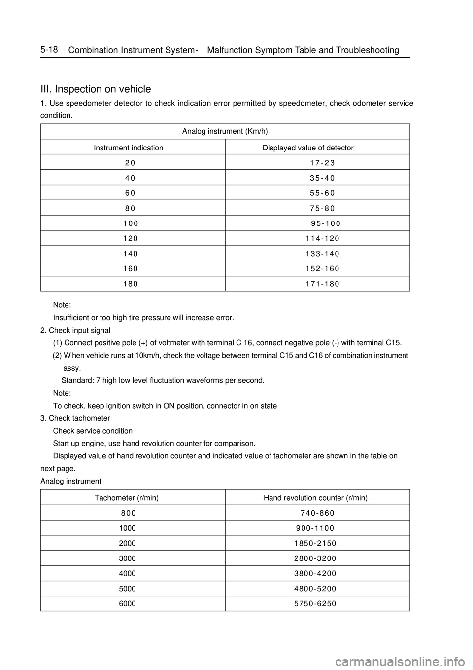
Analog instrument (Km/h)
Instrument indication Displayed value of detector
20 17-23
40 35-40
60 55-60
80 75-80
100 95-100
120 114-120
140 133-140
160 152-160
180 171-180
Tachometer (r/min) Hand revolution counter (r/min)
800 740-860
1000900-1100
20001850-2150
30002800-3200
40003800-4200
50004800-5200
60005750-6250 Note:
Insufficient or too high tire pressure will increase error.
2. Check input signal
(1) Connect positive pole (+) of voltmeter with terminal C 16, connect negative pole (-) with terminal C15.
(2) When vehicle runs at 10km/h, check the voltage between terminal C15 and C16 of combination instrument
assy.
Standard: 7 high low level fluctuation waveforms per second.
Note:
To check, keep ignition switch in ON position, connector in on state
3. Check tachometer
Check service condition
Start up engine, use hand revolution counter for comparison.
Displayed value of hand revolution counter and indicated value of tachometer are shown in the table on
next page.
Analog instrumentIII. Inspection on vehicle1. Use speedometer detector to check indication error permitted by speedometer, check odometer service
condition.5-18Combination Instrument System -Malfunction Symptom Table and Troubleshooting
Page 222 of 416

Section 4 Front Fog Lamp ReplacementI. Removal1. Remove front bumper. (see bumper replacement)
2. Remove electrical connector.
3. Remove fixed bolt (as shown in the figure).
4. Remove front foglight assembly.II. Installation1. Install front foglight assembly.
2. Mount fixed bolt.
3. Mount electrical connector.
4. Mount front bumper.
5. Adjust vehicle state.
6. Adjust front foglight beam.III. Replacement of front head light bulb Remove dust shield by rotating anticlockwise
Pull out bulb plug
Press and loosen steel wire clip
Pull out lamp holder, take off bulb
Replace bulbLight System -Front Fog Lamp Replacement5-351-Turn light dust shield
2-Low beam dust shield
3-High beam, front position lamp dust shieldIII. Replacement of front foglight bulb1. Press and rotate anticlockwise, take off dust hood
2. Take out bulb
3. Replace bulbIV. Adjustment of front foglight beam1. Adjust tire pressure in standard value
2. Start up engine
3. Turn on foglight switch
4. Adjust foglight beam turn screw to adjust foglight beam in the vertical direction.
Description:
Turn screwdriver anticlockwise to make beam upward, or turn screwdriver clockwise to make it downward.