AUX GEELY MK 2008 Workshop Manual
[x] Cancel search | Manufacturer: GEELY, Model Year: 2008, Model line: MK, Model: GEELY MK 2008Pages: 416, PDF Size: 25.19 MB
Page 341 of 416

III. Removal and installation of instrument panel1. Disconnect the negative terminal of storage battery
2. Remove the instrument panel trim panel sub-assembly
a. Loosen 7 clips;
b. Disconnect the connector and unfasten the trim panel.
3. Remove the instrument cluster trim panel sub-assembly
a. Unfix the clamp;
b. Loosen 10 clips and unfasten the trim panel.Steering column upper cover
Steering column lower cover
Auxiliary fasia
console bodyCupholder Instrument cluster trim panel Glove compartment assy Instrument panel
lower housing assyInterior & Exterior Trim and Accessory -Dashboard, Middle Console and Instrument Panel6-12Left Combination switchRight
Combination
switch
7 clips
10 Clips
Page 343 of 416

6-14 e. Pull the instrument panel sub-assembly backward and then take it out.
10. Remove the instrument panel lower housing assembly
Loosen 6 clasps and then pull the lower housing assembly out.
11. Remove the radio set assembly with bracket
a. Unfix 4 screws;
b. Disconnect the connector and then unfasten the radio set
assembly with bracket.
12. Remove the horn button assembly
13. Remove the steering wheel assembly
14. Remove the steering column upper cover assembly
15. Remove the steering column lower cover assembly
16. Remove the cupholder
17. Remove the auxiliary fasia console assembly
a. Unfix 3 screws;
b. Unfix 3 clips by use of a clip remover and then unfasten the
auxiliary fasia console assembly.6 clasps
2 clamps
2 clipsInterior & Exterior Trim and Accessory -Dashboard, Middle Console and Instrument Panel
Page 344 of 416

6-1518. Remove the auxiliary fasia console trim panel
Unfix 6 clips and then unfasten the auxiliary fasia console trim
board
19. Remove the instrument panel lower housing assembly
a. Unfix 2 nuts and
b. Unfix 16 clasps;
c. Unfasten the lower housing assembly.6 clips
16 claspsInterior & Exterior Trim and Accessory -Dashboard, Middle Console and Instrument Panel
Page 368 of 416

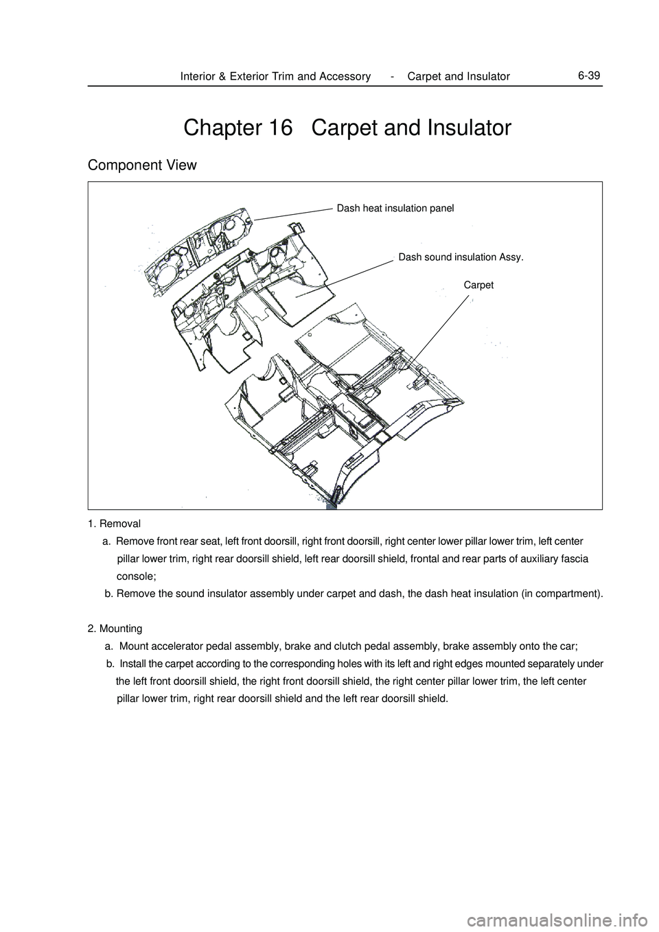
Chapter 16 Carpet and InsulatorComponent ViewCarpet Dash sound insulation Assy. Dash heat insulation panelInterior & Exterior Trim and Accessory -Carpet and Insulator6-391. Removal
a. Remove front rear seat, left front doorsill, right front doorsill, right center lower pillar lower trim, left center
pillar lower trim, right rear doorsill shield, left rear doorsill shield, frontal and rear parts of auxiliary fascia
console;
b. Remove the sound insulator assembly under carpet and dash, the dash heat insulation (in compartment).
2. Mounting
a. Mount accelerator pedal assembly, brake and clutch pedal assembly, brake assembly onto the car;
b. Install the carpet according to the corresponding holes with its left and right edges mounted separately under
the left front doorsill shield, the right front doorsill shield, the right center pillar lower trim, the left center
pillar lower trim, right rear doorsill shield and the left rear doorsill shield.
Page 389 of 416

The body repair starts from the primary rectification or rough rectification. The deformation can be removed
with the supporting method. The angle of the supporting force shall be close to the angle of the external force that
caused the damage. Apply a counterforce at the back of the pulling force point to adjust the supporting force. Make
measurement on the deformation generated in the supporting process. To remove the internal stress, heat the
corresponding parts. For different rectification methods, see Fig. 5-24.
2. Reinforcement
When the local damage, rupture or crack occurs on various components, repair can be made by reinforcement.
Especially for those parts on which damage occurs frequently, special reinforcement measures shall be taken.
However, random reinforcement or component welding shall be avoided, which may affect the body's status.
The reinforcement includes bushing reinforcement, patching reinforcement, arc inlay, and angle plate reinforcement.
3. Local Removal & New Parts Replacement
For the parts with serious corrosion, they must be removed. For the ruptured parts, they shall be replaced
entirely. For the posts manufactured with thin plate by punch, they shall be ordered from the manufacturer. When
the molding is made independently, all specifications (including material, section dimensions and thickness etc.)
shall meet the original design requirement. For the ruptured post (including cross beam), if it is replaced entirely,
it must be connected in the same manner as that of the original post.II. Repair for Body Outside Plate1. Damage Type
a. Crack & Rupture
In the running process, the body vibrates continuously and burdens the loads. When the vehicle makes accident
acceleration, sharp swerve an emergency brake, the body will keep in an inertial status. When the vehicle runs on
the uneven road, bend and distortion will happen on the body.
Affected by these external forces for a long time, crack and rupture may occurs on the stress concentrated parts
and weak structure on the body outside plate.
The stress mostly concentrate on the corner, hem and narrow part of the outside plate, so crack and rupture often
occur on these parts.
b. Corrosion
The corrosion on the outside plate is mostly caused by the mud and water on the metal surface. Only in special
case, it results from the chemical corrosion by chemicals. When the corrosion occurs, rust may appear on the
outside plate and fall gradually, resulting in a hole. On the skirt outside plate and launder, corrosion usually occurs
on the seams between door and frame and the interlayer between the outside plate and the frame.
c. Cave-inFig. 5-24(a) Drawing Rectification Fig. 5-24(b) Drawing & Supporting
RectificationFig. 5-24(c) Auxiliary Force-receiving
Point Rectification7-17washerBody Repair -Repair After Body Damage