window GEELY MK 2008 User Guide
[x] Cancel search | Manufacturer: GEELY, Model Year: 2008, Model line: MK, Model: GEELY MK 2008Pages: 416, PDF Size: 25.19 MB
Page 325 of 416

Chapter 13 Door Glass Regulating and Power Door Lock ControlSection 1 Door Glass Regulating SystemI. Inspection1. Check basic function
(1) Ignition switch is turned "ON" or within 60 s after ignition switch is turned off.
a. Check when rise key of glass regulator switch is pressed, corresponding glass rises, when release, it stops
rising; when press fall key and hold it, corresponding glass falls, when release, it stops falling.
b. Check when glass regulator main control switch lock switch on driver side is pressed,except which on driver
side, other glass regulator switches do not act.
c. Automatic fall: press corresponding glass regulator switch fall key briefly,corresponding glass
regulator motor works, glass falls down to the end; or falls down until rise key or fall key is pressed again.
Notes:
During automatic glass down, if corresponding glass regulator switch fall key is pressed down and held,
glass regulator is changed into manual fall mode; if corresponding glass regulator switch rise key is pressed down
and held, glass regulator is changed into manual rise mode; if corresponding glass regulator switch rise or fall key
is pressed briefly, glass regulator stops work. Press briefly: less than 300ms; press and hold: more than 300 ms.
(2) Close window remotely.
In case setting protection remotely, if a key is pressed for more than 1s, glass regulator automatic window
rising action will be performed, implementation mode: left front, right front, left rear, right back, in the
process of window rise, only one glass regulator is permitted to act, only after glass regulator up to the top,
could the other glass riser act.
2. Glass reguelator switch on driver sideDoor Glass Regulating and Power Door Lock Control-Door Glass Regulating System5-136Glass regulator switch on driver side
Window on front passenger side
Window on driver side
Rear right window
Rear left window
Window locking switch
Page 326 of 416

(1) Check conductibility of the switch.
Standard
Switch position Terminal Result
On driver side
On front passenger side
Left rear
Right rear
Window locking switchUP 12--13 ON
DOWN12---14 ON
UP 12---5 ON
DOWN12---6 ON
UP 12---9 ON
DOWN12---10 ON
UP 12---1 ON
DOWN12---2 ON
Lock12---3 ON
Unlock12---3 OFFResult
Indicator lamp
illuminates If it does not meet stipulation, replace this switch.
(2) Check indicator lamp on glass riser switch on driver side
Storage battery may be connected with terminal of indicator
lamp directly (as shown in the figure)
Standard
If it does not meet stipulation, replace this switch.
3. Other window glass riser switches (passenger side, left rear, right rear)Door Glass Regulating and Power Door Lock Control-
Door Glass Regulating System5-137Connecting condition
Battery positive - terminal 11
Battery negative - terminal 12Other glass regulator switches
Page 349 of 416

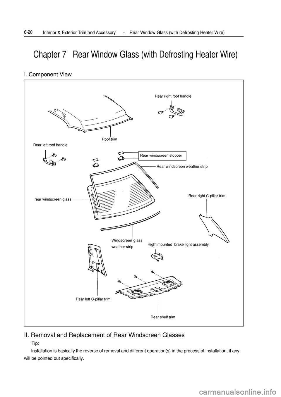
Chapter 7 Rear Window Glass (with Defrosting Heater Wire)II. Removal and Replacement of Rear Windscreen Glasses Tip:
Installation is basically the reverse of removal and different operation(s) in the process of installation, if any,
will be pointed out specifically.I. Component ViewRear right roof handleRoof trim
Rear windscreen stopperRear windscreen weather strip
Rear right C-pillar trim
Windscreen glass
weather stripHight mounted brake light assembly
Rear shelf trim Rear left C-pillar trim rear windscreen glass Rear left roof handleInterior & Exterior Trim and Accessory -Rear Window Glass (with Defrosting Heater Wire)6-20
Page 350 of 416

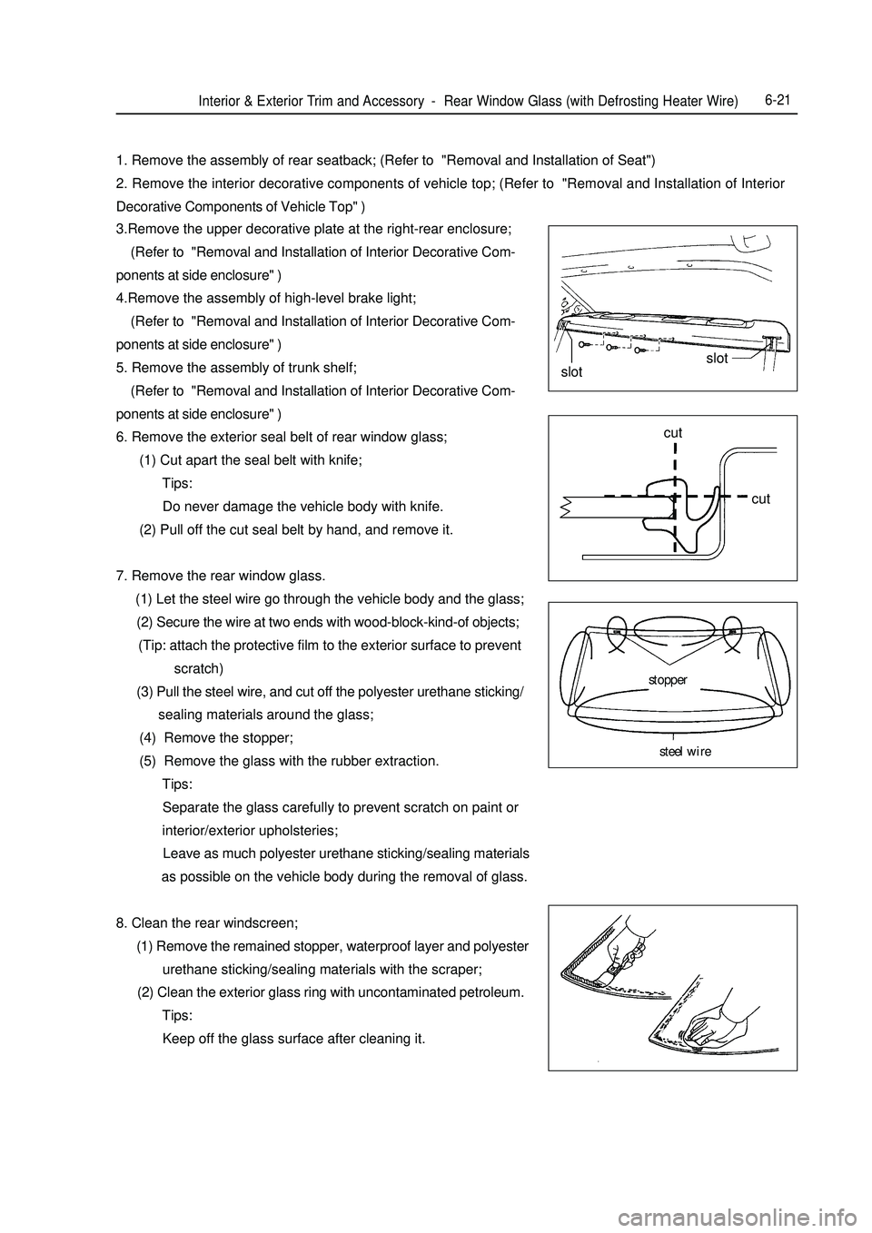
Interior & Exterior Trim and Accessory -Rear Window Glass (with Defrosting Heater Wire)6-211. Remove the assembly of rear seatback; (Refer to "Removal and Installation of Seat")
2. Remove the interior decorative components of vehicle top; (Refer to "Removal and Installation of Interior
Decorative Components of Vehicle Top" )
3.Remove the upper decorative plate at the right-rear enclosure;
(Refer to "Removal and Installation of Interior Decorative Com-
ponents at side enclosure" )
4.Remove the assembly of high-level brake light;
(Refer to "Removal and Installation of Interior Decorative Com-
ponents at side enclosure" )
5. Remove the assembly of trunk shelf;
(Refer to "Removal and Installation of Interior Decorative Com-
ponents at side enclosure" )
6. Remove the exterior seal belt of rear window glass;
(1) Cut apart the seal belt with knife;
Tips:
Do never damage the vehicle body with knife.
(2) Pull off the cut seal belt by hand, and remove it.
7. Remove the rear window glass.
(1) Let the steel wire go through the vehicle body and the glass;
(2) Secure the wire at two ends with wood-block-kind-of objects;
(Tip: attach the protective film to the exterior surface to prevent
scratch)
(3) Pull the steel wire, and cut off the polyester urethane sticking/
sealing materials around the glass;
(4) Remove the stopper;
(5) Remove the glass with the rubber extraction.
Tips:
Separate the glass carefully to prevent scratch on paint or
interior/exterior upholsteries;
Leave as much polyester urethane sticking/sealing materials
as possible on the vehicle body during the removal of glass.
8. Clean the rear windscreen;
(1) Remove the remained stopper, waterproof layer and polyester
urethane sticking/sealing materials with the scraper;
(2) Clean the exterior glass ring with uncontaminated petroleum.
Tips:
Keep off the glass surface after cleaning it.slotslot
cut
cut
stopper
steel wire
Page 359 of 416

Chapter 11 Rear Door Interior TrimI. Component ViewRear left glass guide slot Left window end cover
Rear left window
guide track Rear left corner window weather strip
Rear left window inner weather stripRear Left corner glasses
Rear left windowRear left window
outer weather strip
Rear left window regulator
assembly
Rear left door weather strip Inside handle installation
bracket
gripsPower rear window switchRear left door inside handle
Rear left door
interior trim panel6-30Interior & Exterior Trim and Accessory -Rear Door Interior Trim
Page 360 of 416

6-31II. Removal and Installation of the Rear Door Interior trim Tip:
Installation is basically the reverse of removal and different operation(s) in the process of installation, if any,
will be pointed out specifically.
The removal and installation at the right side are the same as those at the left side.
1. Remove the interior decorative plate handle of left rear door;
Remove a screw with the cross-head screwdriver, and then take
off the interior decorative plate handle of left-rear door.
Tip:
Wrap the head of screwdriver with belt before using it.
2. Remove the assembly of electric-driven window regulator switch;
a. Release the grips with the straight screwdriver, and then re
move the regulator switch off the decorative plate.
b. Disconnect the switch connector.
3. Remove the interior decorative plate of left rear door;
a. Remove the screws and buckles;
b. Release the 6 buckles with the straight screwdriver, and hold
upwards the interior decorative plate of rear-left door to re
move it.
Tip:
Wrap the head of screwdriver with belt before using it.
4. Remove the interior handle of left-rear door;
Release the 2 hooks, remove the interior handle of left-rear door,
and disconnect the 2 wires off the interior handle of left-rear door.
5. Remove off the rain-proof film on the door;clip
HookHookgripsInterior & Exterior Trim and Accessory -Rear Door Interior Trim
Page 361 of 416

Interior & Exterior Trim and Accessory -Rear Door Interior Trim6-326. Remove the rear left window and the guide slot of rear left window;
Tip:
Insert the duster cloth into the interior plate of door to prevent
scratch on glass.
a. Remove the left rear window;
b. Remove the screws and the 2 bolts;
c. Remove the guide slot of rear left window.
7. Remove the rear left corner window;
8. Remove the assembly of left-rear window regulator.
a. Disconnect the connector;
b. Remove the 4 bolts and the assembly of left-rear window
elevator.
Tips:
After removal of bolts, rear left window regulator may fall to
cause damage.
Tip:
Remove the rear left window regulator through the manhole.
Page 379 of 416

(2) Front FenderFront fender plays a role in front wheel apron and rotect person safty.And at the same tirne,if also woork as vehicle
styling parts.
For the match relationship between the front fender & engine hood and the front door, see Fig. 5-9.Fig. 5-9 Front Fender related to surrounding parts
A) With Engine Hood (4mm¡À1mm)
B) With Front Door (5mm¡À1mm)(3) Door Assembly Doors have LH/RH front door and rear door.
The door uses hinge gemel with limiting device, which is an open structure.
The door includes door outside plate, door inside plate, bumper and hinge reinforced plate etc.
The door has a complex structure, which is a movable component on the body. It helps the passengers get on/
off the vehicle and form an enclosed cabin with the main structure and the relevant parts. Meanwhile, the doors
are used frequently, so there is high requirement on their reliability and durability.
The outside/inside plate is molded by one complete steel sheet, which can improve the stiffness and precision.
In order to improve the safety when the vehicle is collided from the side, four doors are equipped with door
bumpers.
As shown in Fig. 5-10 and Fig. 5-11, the door assembly is made up of outside plate assembly and inside plate
assembly.Fig. 5-10 Front Door
1. Front door inner panel 2. Left front door inner reinforced panel 3. Front door window opper rail 4. Door lock reinforced panel
5. Left front door inner plate cross beam 6. Front door outer panel 7. Door bumper assembly
8. Front door upper hinge assembly 9. Front door lower hinge assembly 10. Hinge reinforced panel assemblySurvey -Body Structure7-7Engine hood
Front fenderFront door
Front fenderA
B12345678910
Page 382 of 416

3. External Force Having an Angle with Vehicle Centerline (Fig. 5-15)Body Repair -Body Damage Forms and requirements For Repair7-10Fig. 5-15 External Force Having an Angle with Vehicle Centerline As shown in Fig. 5-15, when the vehicle is acted by an external force having an angle with its centerline, the
force will affect the hood root and the front window side post if it is strong enough.
4. Body Side Center Acted by External Force in Upright Direction (Fig. 5-16)Fig. 5-16 Body Side Center Acted by External Force in Upright Direction As shown in Fig. 5-16, when the body side center is acted by an external force in the upright direction, check
the following positions:
a. Front window side post upper/lower installation position;
b. Side window intermediate post upper/lower installation position;
c. Side window rear post deformation;
d. Roof and frame deformation.
When the body is acted by an external force on the rear part, its damage is the same as that caused by an external
force on the front part. Check the parts in full consideration of the rear structure and feature.External ForceExternal Force
Page 412 of 416

3. Body Opening Part (Back View)
A-d 1504±2.5
4
a-D 1504±2.5
C-d 1191±2.5
4
c-D 1191±2.5
f-G 1217±2.5
4
F-g 1217±2.5
e-B 1599±2.5
4
E-b 1599±2.5
h-I 1003±2.5
4
H-i 1003±2.5
(mm)
Item Description
Diameter of Hole
XYZ
A,a
Back window glass fastener installation hole
11.5¡Á8.52327.46 +/-374.49 1118.41
B,b
Rear absorber spring support hole
18 2506.99 +/-534.81 550.09
C,c Tall lamp installation hole 5 3190.8 +/-679.49 632.24
D,d Rear bumperinstallation bole 15 3202.45 +/-428.13 195.64
E,e B-pillar rear assembly mark - 1493.1 +/-672.96 812.59
F,f
Rear joint between side outer panel and roof panel
- 2310.74 +/-598.88 1106.12
G,g
Joint between side outer panel and luggage compartment
- 2816.19 +/-569.92 831.4
H,h
Joint between side outer panel and tail lmap panel
- 2987.01 +/-569.92 798.34
I,i
Rear joint between side outer panel and rear end panel
- 3327.63 +/-325.23 500.2Appendix-Body Key Dimensions7-40
Measuring
point
Value
Tolerance