ABS GEELY MK 2008 Owner's Manual
[x] Cancel search | Manufacturer: GEELY, Model Year: 2008, Model line: MK, Model: GEELY MK 2008Pages: 416, PDF Size: 25.19 MB
Page 100 of 416

15. Install LF steering knuckle assembly
Notice:
The hub bearing could be damaged if it is subjected to the vehicle
weight, such as when moving the vehicle with the drive shaft
bearing removed.
Therefore if it is absolutely necessary to place the vehicle weight
on the hub bearing, first support it with the special service tool for
front hub bearing.
16. Check left constant velocity drive shaft assembly
(1) Check the outboard joint for apparent looseness.
(2) Check that the inboard joint slide smoothly.
(3) Check the inboard joint for radial looseness.
(4) Check the boot for damage.
Notice:
Place the drive shaft assembly on level surface during the
inspection.
17. Remove inboard joint big clamp
Using a screw driver, loosen the inboard joint big clamp.
18. Remove inboard joint small clamp
Using a screw driver, loosen the inboard joint small clamp.
19. Separate inboard joint boot
Separate the outboard joint boot from the outboard Rzeppa joint
assembly.
20. Remove left tripod joint assembly
(1) Wipe off the old grease from the tripod joint assembly.
(2) Place the matchmarks between the tripod joint assembly and
the outboard Rzeppa joint.
Notice:
Do not punch the matchmarks.Propeller Shaft/DriveshaftFront Driveshaft4-23Mark -
Page 105 of 416

Propeller Shaft/DriveshaftFront Driveshaft4-28 Hint:
Please refer to the following table for dimension (A).LH mm
528.3±5.0
527.0±5.0RH mm
859.3±5.0
860.0±5.0 M/T manual transmission
A/T automatic transmission38. Install left constant velocity drive shaft assembly
(1) M/T
Coat the spline of the tripod joint assembly with gear oil.
(2) A/T
Coat the spline of the tripod joint assembly with ATF
(Automatic Transmission Fluid).
(3) Align the spline, use a brass bar and hammer to install the left
drive shaft assembly.
Notice:
Face the retainer open end downward.
Be careful not to damage the boot and oil seal.
Hint:
You can find out whether the tripod joint shaft contact the pinion shaft by rotating the shaft assembly, listening
to the sound and feeling.
39. Install right constant velocity drive shaft assembly
Hint:
The installation of the right side is the same as that of the left side.
Notice:
Install the retainer with its open end facing downward.
Be careful not to damage the boot and oil seal.
40. Install left steering knuckle assembly
Install the left constant velocity drive shaft assembly on the left steering knuckle assembly.
Notice:
Be careful not to damage the outboard joint boot.
With ABS:
Be careful not to damage the vehicle speed sensor rotor.
41. Install left steering gear with tie rod assembly
(1) Install the steering gear with tie rod assembly on the steering knuckle assembly with nuts.
Torque: 33N.m
(2) Install the new cotter pins.
Notice:
If the pin holes are not aligned, further tighten the nut by 60°.
42. Install left lower swing arm assembly
(1) Install the left lower swing arm assembly on the steering knuckle assembly with nuts.
Torque: 98N.m -
Page 106 of 416

Propeller Shaft/DriveshaftFront Driveshaft4-29 (2) Install the new cotter pins.
Notice:
If the pin holes are not aligned, further tighten the nut by 60°.
43. Install front stabilizer bar
(1) As shown in the illustration, install the stabilizer bar with two
No.1 collars and two gaskets and nuts.
Notice:
Make sure the gaskets and collars are correctly installed.
(2) Tighten the nut with a 10mm wrench.
Torque: 18N.m
44. Install left front vehicle speed sensor (with ABS)
(1) Install the left front vehicle speed sensor and brake hose on the
front shock absorber with bolts and clps.
Torque: 29N.m
(2) Install the vehicle speed sensor on the steering knuckle with
bolts.
Torque: 8.0N.m
Notice:
Be careful not to damage the wheel speed sensor.
Keep the vehicle speed sensor clean.
When installing the sensor,do not twist the sensor wire harness.
45. Install left steering knuckle wheel hub nut
(1) Install new left steering knuckle hub nuts
Torque: 216N.m
(2) Using a chisel and hammer, stake the hub locking nut.
46. Install engine bottom left shield
47. Install engine bottom right shield
48. Install engine bottom shield assembly
49. Install front wheel
Torque: 103 N.m
50. Add oil into manual transmission
51. Check and adjust the manual transmission fluid
52. Refill automatic transmission fluid
53. Check and adjust the automatic transmission fluid
54. Check and adjust front wheel alignment
55. Check ABS vehicle speed signal (with ABS) -
Page 107 of 416

Section 3 Front Wheel HubComponent ViewLeft Constant Velocity
Drive Shaft Assembly
Left Brake Caliper Assembly
Retainer
Dual Ball Bearing
Left Steering Knuckle
Front Axle Hub Front Axle Hub NutBrake DiscPropeller Shaft/DriveshaftFront Wheel Hub4-30With ABS
Left Front Vehicle
Speed Sensor
Left Tie Rod End Subassembly
Brake Hose
Left Front Axle Assembly
No. 1 Cushion Collar
Cotter Pin
Cushion
ClipFront Stabilizer
Left No.1 Front Lower
Suspension Arm
SubassemblyLeft Front Axle Hub Nut
Left Front Brake Disc Dust Cover
specified torqueN.
m :No. 1 Cushion Collar - Non-reusable parts -
Page 108 of 416

Propeller Shaft/DriveshaftFront Wheel Hub4-31Replacement1. Remove front wheel
2. Using a drive shaft nut chisel, remove the front axle hub left nut
3. Remove left front vehicle speed sensor (with abs)
4. Remove left front brake caliper assembly
Remove 2 bolts, remove the left front brake caliper assembly
from the steering knuckle.5. Remove front brake disc
6. Remove front stabilizer
7. Remove left no.1 front lower suspension arm subassembly with a ball joint puller
8. Remove left tie rod end subassembly with a ball joint puller
9. Remove left front axle assembly
10. Remove left front shock absorber assembly
Remove 2 sets of bolts and nuts, remove the left front shock
absorber from the left front axle assembly.
11. Remove left front axle hub snap ring
Using a snap ring plier, remove front axle hub left snap ring.
12. Remove left front axle hub subassembly
(1) Remove the left front axle hub subassembly with rear axle
puller. -
Page 110 of 416

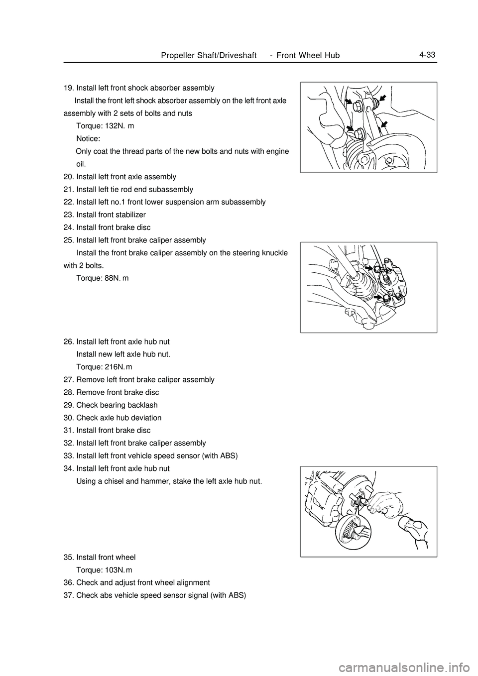
Propeller Shaft/DriveshaftFront Wheel Hub4-3319. Install left front shock absorber assembly
Install the front left shock absorber assembly on the left front axle
assembly with 2 sets of bolts and nuts
Torque: 132N.m
Notice:
Only coat the thread parts of the new bolts and nuts with engine
oil.
20. Install left front axle assembly
21. Install left tie rod end subassembly
22. Install left no.1 front lower suspension arm subassembly
23. Install front stabilizer
24. Install front brake disc
25. Install left front brake caliper assembly
Install the front brake caliper assembly on the steering knuckle
with 2 bolts.
Torque: 88N.
m
26. Install left front axle hub nut
Install new left axle hub nut.
Torque: 216N.m
27. Remove left front brake caliper assembly
28. Remove front brake disc
29. Check bearing backlash
30. Check axle hub deviation
31. Install front brake disc
32. Install left front brake caliper assembly
33. Install left front vehicle speed sensor (with ABS)
34. Install left front axle hub nut
Using a chisel and hammer, stake the left axle hub nut.
35. Install front wheel
Torque: 103N.m
36. Check and adjust front wheel alignment
37. Check abs vehicle speed sensor signal (with ABS) -
Page 112 of 416

Propeller Shaft/DriveshaftRear Wheel Hub and Bearing Assembly4-35Section 4 Rear Wheel Hub and Bearing AssemblyComponent ViewRear Axle Hub UnitBrake Drum Assembly
specified torqueN.
m :Slip Control Sensor Wire Harness
With ABS
Left Rear Axle Hub Bolt - Non-reusable parts
Page 113 of 416

Replacement1. Remove rear wheel
2. Remove rear wheel brake drum subassembly
3. Remove slip control sensor wire harness (with ABS)
4. Remove left rear axle hub and bearing assembly
Remove 4 bolts and left axle hub and bearing assembly.
5. Install left rear axle hub and bearing assembly
Install left axle hub and bearing assembly with 4 bolts
Torque: 63N.m
6. Connect slip control sensor wire harness (with ABS)
Notice:
Do not twist the sensor wire harness during connection.
7. Check bearing backlash
8. Check axle hub deviation
9. Install rear wheel brake drum subassembly
10. Install rear wheel
Torque: 103N.m
11. Check as vehicle speed sensor signal (with ABS)Propeller Shaft/DriveshaftRear Wheel Hub and Bearing Assembly4-36 -
Page 115 of 416

Chapter 5 Front Suspension SystemSection 1 Front Suspension SystemDescription on front suspension structureThis model uses strut swing arm independent suspension with stabilizer bar.
The shock absorber upper end is flexibly connected to the body through the shock absorber mounting seat, the
lower end is rigidly connected to the steering knuckle. The coil spring encloses the shock absorber (coil spring
geometrical axial line does not coincide with that of the shock absorber piston rod), and is supported between the
upper and lower spring seats.
Both ends of the stabilizer bar are connected to the shock absorber through the strut bar ball pin and the intermediate
part is supported on the lower front body by the rubber bushing and support frame.
The front cushion sleeves the shock absorber piston rod head to restrict the wheel jump limit position and plays
the role of buffer.
The thrust ball bearing, installed between the spring upper seat and the shock absorber mount, is used for the
relative rotation upon steering of the shock absorber rigidly connected to the steering knuckle to the shock absorber
mount flexibly connected to the body.
"L" type lower swing arm is secured to the lower engine compartment with the press plate through elastic rubber
bushing and hinge, and its outer end is connected to the steering knuckle through the ball stud pin which is attached
to the lower swing arm by 3 high intension bolts. The ball stud pin can be removed and replaced when it is worn.
The ball seat material is saturated polyester containing oil, featured in comparatively high intensity and wearability
and good self-lubrication performance. Proper amount of grease has been added during the assembly and there is
no need for additional filling during the normal operation.See the table for the front suspension technical parametersFront Suspension SystemFront Suspension System4-38Item
Shock absorber operating cylinder diameter /mm
Shock absorber piston rod diameter /mm
Shock absorber stroke/mm
Wheel camber
Wheel toe-in/mm
King pin inclination
King pin caster
Remark: the wheel alignment parameter in the table is at free load.Parameter
45
20
160
-0°30'±45'
1±2
10°0'±45'
2°0'±45' -
Page 116 of 416

Suspected Area
1. Tires (Worn or improperly inflated)
2. Wheel alignment (Incorrect)
3. Steering system joint (Loose or worn)
4. Hub bearing (Worn)
5. Steering gear (Out of adjustment or worn)
6. Suspension parts (Worn or damaged)
1. Vehicle (Overloaded)
2. Spring (stiffness not comply with or damage)
3. Shock absorber (Worn)
1. Tire (Worn or improperly inflated)
2. Steering linkage (Loose or damaged)
3. Stabilizer bar (Bent or broken)
4. Shock absorber (Worn or damaged)
1. Tire (Worn or improperly inflated)
2. Tire (Dynamic balance is not as specified)
3. Shock absorber (Worn or damaged)
4. Wheel alignment (Incorrect)
5. Ball stud pin (Worn or damaged)
6. Hub bearing (Worn or damaged)
7. Steering linkage (Loose or worn)
8. Steering gear (Out of adjustment or worn)
1. Tire (Worn or improperly inflated)
2. Wheel alignment (Incorrect)
3. Shock absorber (Worn or damaged)
4. Suspension parts (Worn or damaged)Symptom Table Use the table below to help you find the cause of the problem. The numbers indicate the priority of the likely
cause of the problem. Check each part in order. If necessary, replace parts.
Symptom
Off track
Body Descent
Sways
Front wheel shimmy
Abnormal tire wearFront Suspension System-Front Suspension System4-39