ABS GEELY MK 2008 Repair Manual
[x] Cancel search | Manufacturer: GEELY, Model Year: 2008, Model line: MK, Model: GEELY MK 2008Pages: 416, PDF Size: 25.19 MB
Page 166 of 416
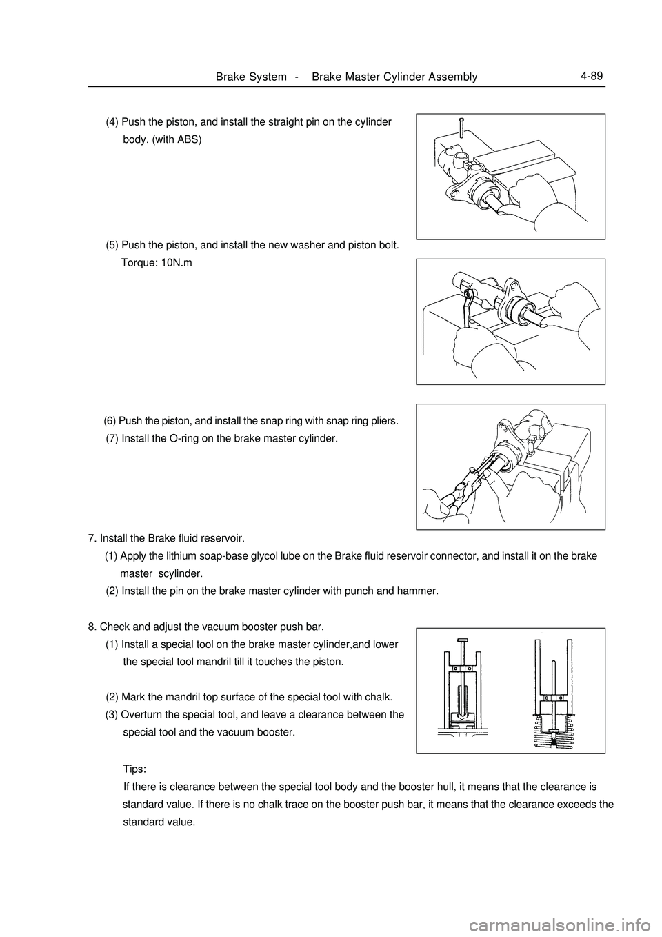
Brake System -Brake Master Cylinder Assembly4-89 (4) Push the piston, and install the straight pin on the cylinder
body. (with ABS)
(5) Push the piston, and install the new washer and piston bolt.
Torque: 10N.m
(6) Push the piston, and install the snap ring with snap ring pliers.
(7) Install the O-ring on the brake master cylinder.
7. Install the Brake fluid reservoir.
(1) Apply the lithium soap-base glycol lube on the Brake fluid reservoir connector, and install it on the brake
master scylinder.
(2) Install the pin on the brake master cylinder with punch and hammer.
8. Check and adjust the vacuum booster push bar.
(1) Install a special tool on the brake master cylinder,and lower
the special tool mandril till it touches the piston.
(2) Mark the mandril top surface of the special tool with chalk.
(3) Overturn the special tool, and leave a clearance between the
special tool and the vacuum booster.
Tips:
If there is clearance between the special tool body and the booster hull, it means that the clearance is
standard value. If there is no chalk trace on the booster push bar, it means that the clearance exceeds the
standard value.
Page 167 of 416
Brake System -Brake Master Cylinder Assembly4-90 (4) Adjust the length of the vacuum booster push bar with the
special tool till the push bar touches the mandril head.
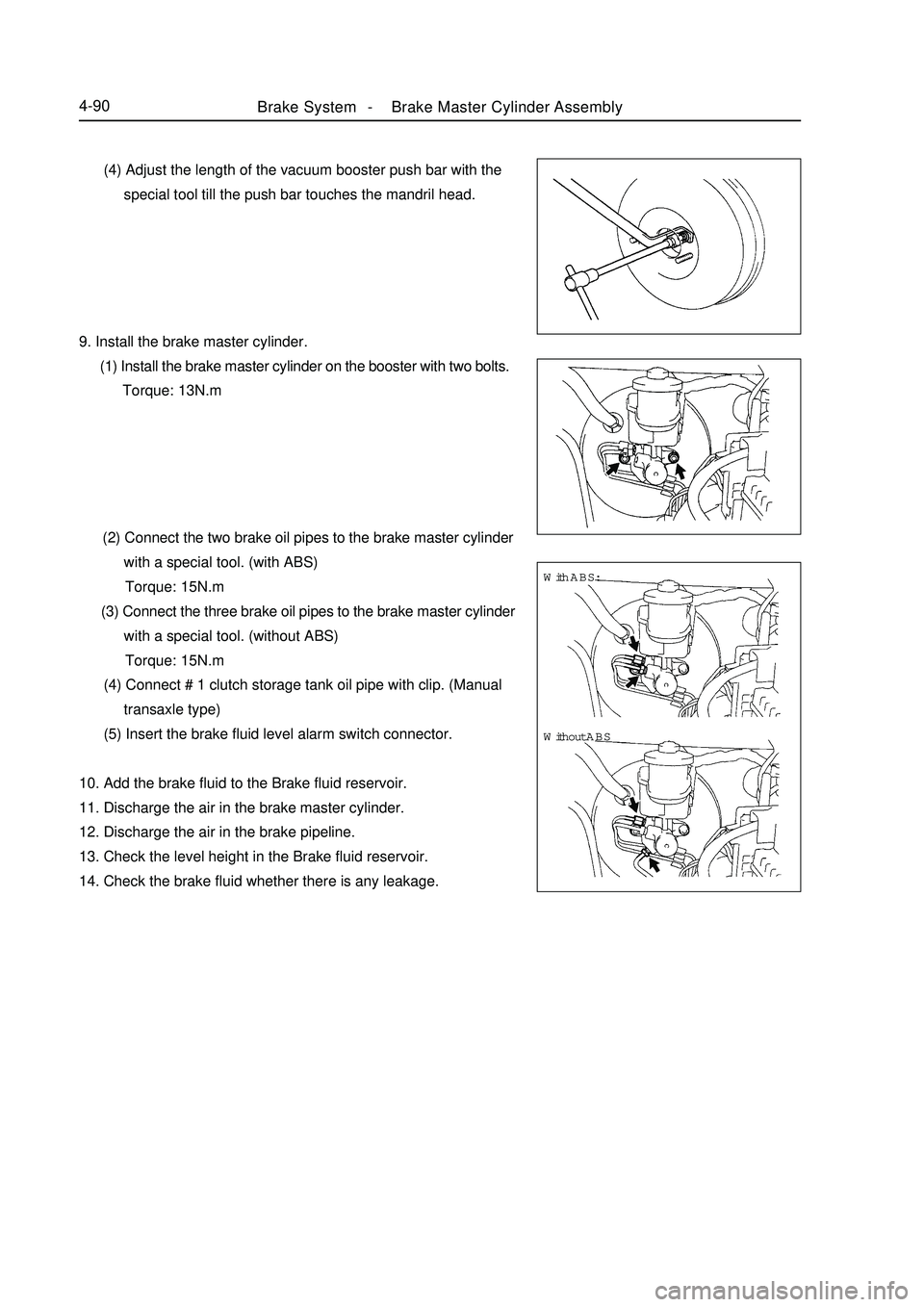
9. Install the brake master cylinder.
(1) Install the brake master cylinder on the booster with two bolts.
Torque: 13N.m
(2) Connect the two brake oil pipes to the brake master cylinder
with a special tool. (with ABS)
Torque: 15N.m
(3) Connect the three brake oil pipes to the brake master cylinder
with a special tool. (without ABS)
Torque: 15N.m
(4) Connect # 1 clutch storage tank oil pipe with clip. (Manual
transaxle type)
(5) Insert the brake fluid level alarm switch connector.
10. Add the brake fluid to the Brake fluid reservoir.
11. Discharge the air in the brake master cylinder.
12. Discharge the air in the brake pipeline.
13. Check the level height in the Brake fluid reservoir.
14. Check the brake fluid whether there is any leakage.With ABS:
Without ABS
Page 168 of 416

19151915131515
Fluid level indicator lamp connectorVacuum booster assembly
Gasket25Clip26 Clip Master cylinder
Manual Transmission
#1 clutch fluid tank oil pipe
HECU assemblyClipSection 5 Vacuum BoosterComponent ViewBrake System -Vacuum Booster4-91Battery
#2 relay box, engine chamber
Return spring
Pin
Push bar
U-connector Without ABSVacuum tube
Non-reusable parts
Lithium soap base glycol lubeSpecified torque
Page 170 of 416
Brake System -Vacuum Booster4-93Replacement1. Discharge the brake fluid.
Note:
Never spray the brake fluid on the paint surface, otherwise wash it immediately.
2. Unfix the clutch fluid tank pipe (manual transaxle).
3. Remove the brake master cylinder.
4. Remove the HECU assembly (with ABS).
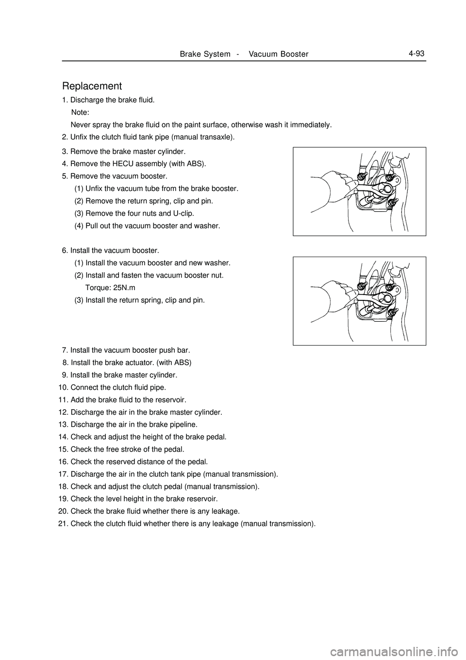
5. Remove the vacuum booster.
(1) Unfix the vacuum tube from the brake booster.
(2) Remove the return spring, clip and pin.
(3) Remove the four nuts and U-clip.
(4) Pull out the vacuum booster and washer.
6. Install the vacuum booster.
(1) Install the vacuum booster and new washer.
(2) Install and fasten the vacuum booster nut.
Torque: 25N.m
(3) Install the return spring, clip and pin.
7. Install the vacuum booster push bar.
8. Install the brake actuator. (with ABS)
9. Install the brake master cylinder.
10. Connect the clutch fluid pipe.
11. Add the brake fluid to the reservoir.
12. Discharge the air in the brake master cylinder.
13. Discharge the air in the brake pipeline.
14. Check and adjust the height of the brake pedal.
15. Check the free stroke of the pedal.
16. Check the reserved distance of the pedal.
17. Discharge the air in the clutch tank pipe (manual transmission).
18. Check and adjust the clutch pedal (manual transmission).
19. Check the level height in the brake reservoir.
20. Check the brake fluid whether there is any leakage.
21. Check the clutch fluid whether there is any leakage (manual transmission).
Page 196 of 416
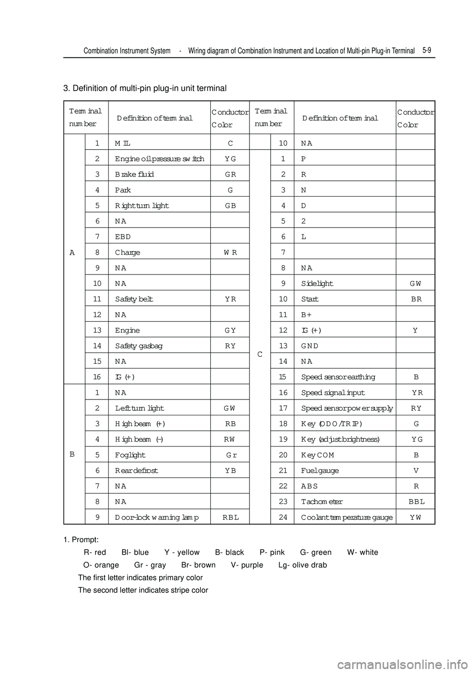
3. Definition of multi-pin plug-in unit terminal
1. Prompt:
R- red Bl- blue Y - yellow B- black P- pink G- green W- white
O- orange Gr - gray Br- brown V- purple Lg- olive drab
The first letter indicates primary color
The second letter indicates stripe colorTerminal
number1 MIL C 10 NA
2 Engine oil pressure switch YG 1 P
3 Brake fluid GR 2 R
4 Park G 3 N
5 Right turn light GB 4 D
6NA 52
7 EBD 6 L
8 Charge WR 7
9NA 8NA
10 NA 9 Sidelight GW
11 Safety belt YR 10 Start BR
12 NA 11 B+
13 Engine GY 12IG ( + ) Y
14 Safety gasbag RY 13 GND
15 NA 14 NA
16 IG ( + ) 15Speed sensor earthing B
1 NA 16 Speed signal input YR
2 Left turn light GW 17 Speed sensor power supply RY
3 High beam (+) RB 18 Key (ODO/TRIP) G
4 High beam (-) RW 19 Key (adjust brightness) YG
5 Foglight Gr 20 Key COM B
6 Rear defrost YB 21 Fuel gauge V
7 NA 22 ABS R
8 NA 23 Tachometer BBL
9 Door-lock warning lamp RBL 24 Coolant temperature gauge YWA
BCCombination Instrument System -Wiring diagram of Combination Instrument and Location of Multi-pin Plug-in Terminal5-9Definition of terminalConductor
ColorTerminal
numberDefinition of terminalConductor
Color
Page 203 of 416

Suspected area
1. Wiring harness or connector
2. ECM
3. Combination instrument assy.
1. Wiring harness or connector
2. Alternator
3. Combination instrument assy.
1. Wiring harness or connector
2. Manual brake switch
3. Combination instrument assy.
1. Wiring harness or connector
2. Brake fluid level switch
3. Combination instrument assy.
1. Wiring harness or connector
2. ABS ECU or ABS warning lamp driving module
3. Combination instrument assy.
1. Wiring harness or connector
2. Airbag ECU controller
3. Combination instrument assy.
1. Wiring harness or connector
2. Airbag ECU controller
3. Combination instrument assy.
1. Wiring harness or connector
2. Front head light dimmer switch
3. Combination instrument assy.
1. Wiring harness or connector
2. Front head light dimmer switch
3. Combination instrument assy.
1. Wiring harness or connector
2. Rear defrost switch
3. Combination instrument assy. 8. Warning lamp fails
Symptom
Check that engine warning lamp does not
illuminate
Charge warning lamp does not illuminate
Park braking warning lamp does not
illuminate
Brake failure warning lamp does not
illuminate
ABS warning lamp does not illuminate
SRS warning lamp does not illuminate
Passenger's airbag indicator lamp does
not illuminate
High beam indicator lamp does not
illuminate
Rear foglight indicator lamp does not
illuminate
Rear defrost indicator lamp does not
illuminate5-16Combination Instrument System -Malfunction Symptom Table and Troubleshooting
Page 226 of 416

Notes:
If noise occurred does not belong to any of the above-mentioned situations, please find out the cause according
to "receiving problem".
5. CD phonograph
CD phonograph (hereafter referred to as CD) uses laser beam to read digital signals recorded on CD, then revert
to analog signal of music.
Notes:
Don't attempt to break down or apply oil to any component of the phonograph. Do not insert anything other
than a CD into optical disk cartridge.
Notes:
CD phonograph uses invisible laser beam, could generate harmful radialization, always operate phonograph
according to instructions.
6. Maintenance
(1) Cleaning of magnetic tape phonograph, magnetic head:
a. Open tape cartridge gate with your finger, use a pencil or a similar article to insert guider.
b. use cleaning pen or cotton swabs with detergent to wipe magnetic head surface, idler wheel or guide
pulley.
(2) CD phonograph, CD cleaning:
If CD is dirty, use soft cloth to wipe the surface from CD center radially outwards.
Notes:
Don't use ordinary recorder detergent or antistatic protectant. 4. Noise problem
Detailed description of noise problem fed back by customers is of great importance for analyzing and
eliminating noise interference, the table below may be used for diagnosis.Audio System -Audio System Description5-39Noise condition
Noise occurs in special position
Noise occurs when receiving small
signal
Noise only occurs at night
Noise occurs in special position
during driving Radio wave
AM
FMCause
Most probably external noise
Broadcast from local station might broadcast the same
program. If program is the same, one of them might be
disturbed
Most probably from remote interference
Most probably is multiplex interference due to FM
frequency changeExample:
Magnetic head
Guide pulley
Idler wheel
Page 286 of 416
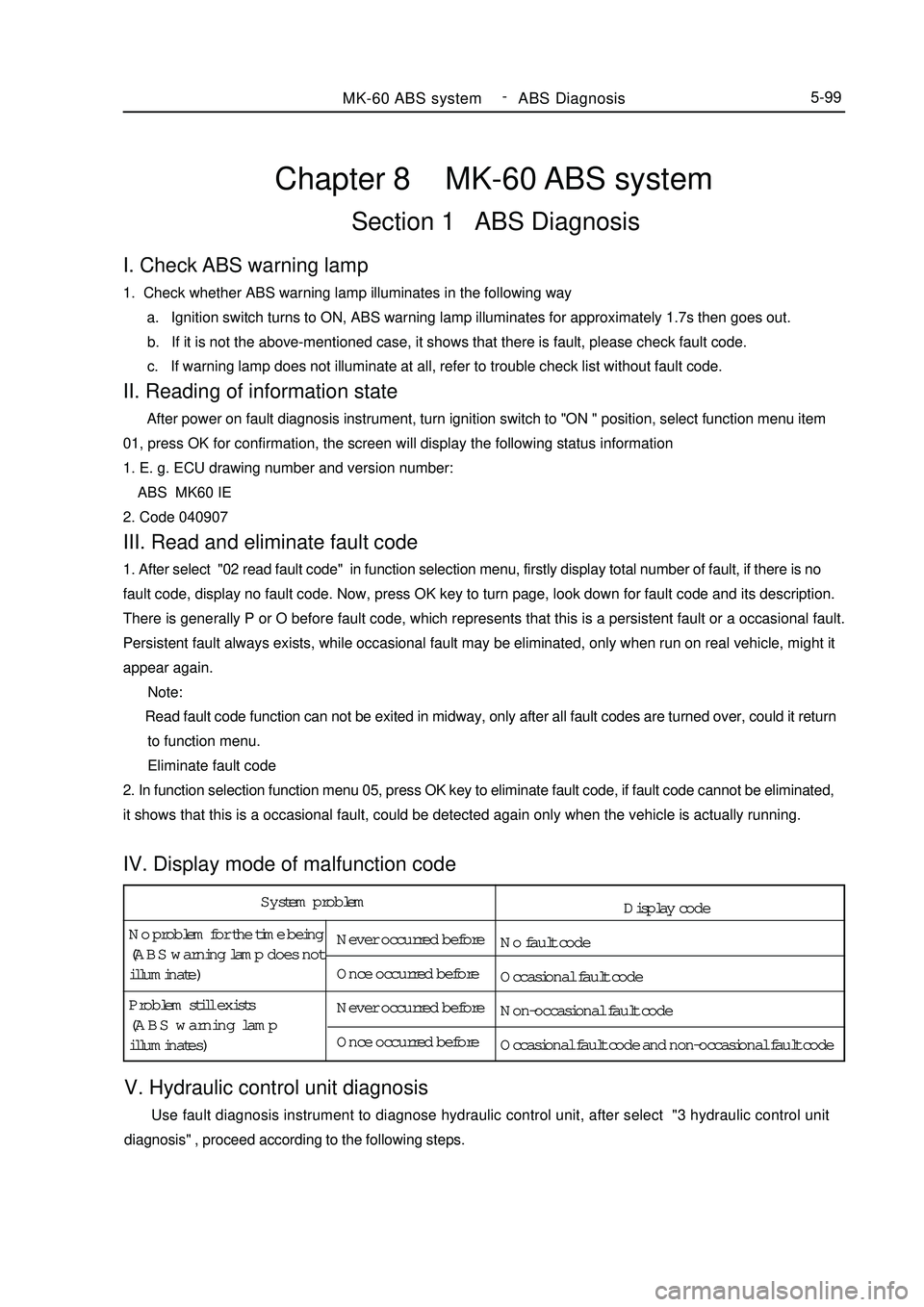
System problem
No problem for the time being
(ABS warning lamp does not
illuminate)Never occurred before
Once occurred before
Never occurred before
Once occurred before Problem still exists
(ABS warning lamp
illuminates)Chapter 8 MK-60 ABS systemSection 1 ABS DiagnosisV. Hydraulic control unit diagnosis Use fault diagnosis instrument to diagnose hydraulic control unit, after select "3 hydraulic control unit
diagnosis" , proceed according to the following steps.MK-60 ABS system -
ABS Diagnosis5-99I. Check ABS warning lamp1. Check whether ABS warning lamp illuminates in the following way
a. Ignition switch turns to ON, ABS warning lamp illuminates for approximately 1.7s then goes out.
b. If it is not the above-mentioned case, it shows that there is fault, please check fault code.
c. If warning lamp does not illuminate at all, refer to trouble check list without fault code.II. Reading of information state After power on fault diagnosis instrument, turn ignition switch to "ON " position, select function menu item
01, press OK for confirmation, the screen will display the following status information
1. E. g. ECU drawing number and version number:
ABS MK60 IE
2. Code 040907III. Read and eliminate fault code1. After select "02 read fault code" in function selection menu, firstly display total number of fault, if there is no
fault code, display no fault code. Now, press OK key to turn page, look down for fault code and its description.
There is generally P or O before fault code, which represents that this is a persistent fault or a occasional fault.
Persistent fault always exists, while occasional fault may be eliminated, only when run on real vehicle, might it
appear again.
Note:
Read fault code function can not be exited in midway, only after all fault codes are turned over, could it return
to function menu.
Eliminate fault code
2. In function selection function menu 05, press OK key to eliminate fault code, if fault code cannot be eliminated,
it shows that this is a occasional fault, could be detected again only when the vehicle is actually running.IV. Display mode of malfunction codeDisplay code
No fault code
Occasional fault code
Non-occasional fault code
Occasional fault code and non-occasional fault code
Page 287 of 416
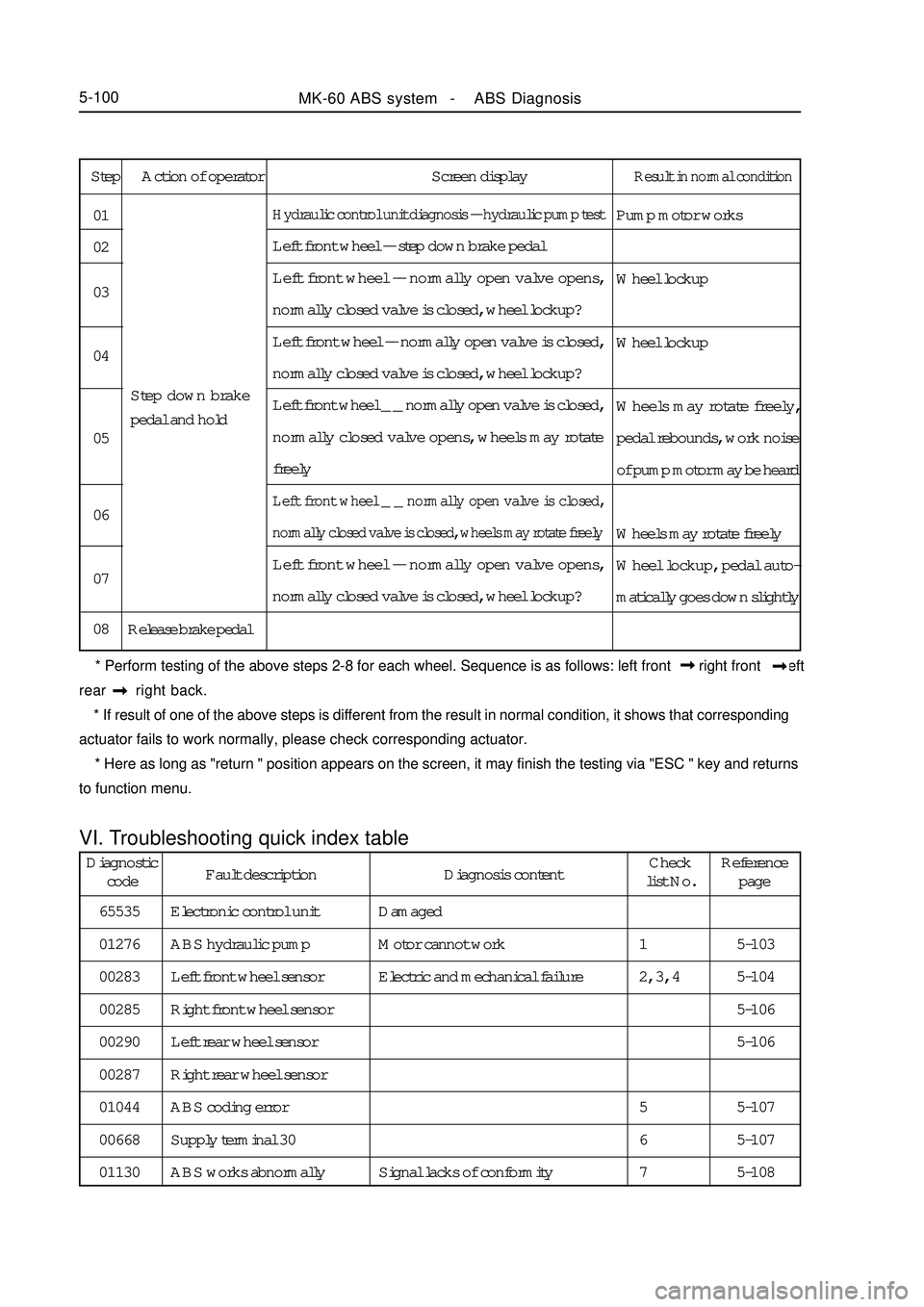
Step Action of operator Screen displayResult in normal conditionPump motor works
Wheel lockup
Wheel lockup
Wheels may rotate freely,
pedal rebounds, work noise
of pump motor may be heard
Wheels may rotate freely
Wheel lockup, pedal auto-
matically goes down slightlyHydraulic control unit diagnosis -- hydraulic pump testLeft front wheel -- step down brake pedal
Left front wheel -- normally open valve opens,
normally closed valve is closed, wheel lockup?
Left front wheel -- normally open valve is closed,
normally closed valve is closed, wheel lockup?
Left front wheel _ _ normally open valve is closed,
normally closed valve opens, wheels may rotate
freelyLeft front wheel _ _ normally open valve is closed,
normally closed valve is closed, wheels may rotate freelyLeft front wheel -- normally open valve opens,
normally closed valve is closed, wheel lockup?
Release brake pedal 01
02
03
04
05
06
07
08Step down brake
pedal and hold
* Perform testing of the above steps 2-8 for each wheel. Sequence is as follows: left front right front left
rear right back.
* If result of one of the above steps is different from the result in normal condition, it shows that corresponding
actuator fails to work normally, please check corresponding actuator.
* Here as long as "return " position appears on the screen, it may finish the testing via "ESC " key and returns
to function menu.VI. Troubleshooting quick index tableMK-60 ABS system - ABS Diagnosis5-100Diagnostic
codeFault description Diagnosis contentCheck
list No.Reference
page
65535
01276
00283
00285
00290
00287
01044
00668
01130Electronic control unit
ABS hydraulic pump
Left front wheel sensor
Right front wheel sensor
Left rear wheel sensor
Right rear wheel sensor
ABS coding error
Supply terminal 30
ABS works abnormallyDamaged
Motor cannot work
Electric and mechanical failure
Signal lacks of conformity5-103
5-104
5-106
5-106
5-107
5-107
5-108 1
2, 3, 4
5
6
7
Page 288 of 416
VIII. Circuit diagramVII. Check list index of fault without fault codeMK-60 ABS system -ABS Diagnosis5-101Fault condition
When Ignition switch is turned to "ON " (engine stall condition), ABS
warning lamp does not illuminate
After Engine is started, warning lamp does not go outCheck list No.
1
2
3
4
5
6Reference page
5-109
5-110
5-111
5-112
5-112
5-113 ABS works
abnormallyBraking force on both sides is not even
Braking force is insufficient
When brake pedal is stepped on slightly, ABS works
(automobile in idle state)
When brake pedal is stepped on slightly, ABS works
(automobile in running state)
When ABS works, brake pedal vibrates excessively
Travel of brake pedal is too long
A very large force is needed to step on brake pedal
No fault code output (cannot communicate with fault diagnosis instrument)Please Refer to "MK WIRING DIAGRAM"