key GEELY MK 2008 Owner's Manual
[x] Cancel search | Manufacturer: GEELY, Model Year: 2008, Model line: MK, Model: GEELY MK 2008Pages: 416, PDF Size: 25.19 MB
Page 296 of 416

Check ABS warning lamp
safety wire in fuse boxCheck
ABS warning lamp safety wire
in fuse boxReplace AbnormalRemove ECU joint, when igni-
tion switch is in ON, does warn-
ing lamp illuminate ?NoNormalCheck whether ABS warn-
ing lamp is burnt outYes
ReplaceCheck whether warning
lamp power supply circuit
and ground loop in wiring
harness is disconnectedAbnormalRepair wiring
harnessCheck warning lamp power
supply circuit and ground
loop socket connector in
wiring harnessAbnormalRepair socket
connectorDoes fault reoccurNoRepair wiring harnessYe s NormalNormal NoRefer to key point
for repair of occa-
sional faultII. Check list of fault without malfunction codeMK-60 ABS system -ABS System Check5-109When ignition switch is in ON position (engine stall), ABS warning
lamp does not illuminate 1
[Description ] ABS warning lamp does not illuminate, warning lamp power
supply circuit might be disconnected, bulb is burnt out or
warning lamp driving module is damaged.Possible cause
Safety wire is burnt out
ABS warning lamp bulb
is burnt out
Power circuit is discon-
nected
ABS warning lamp driv-
ing module is damaged
YesCheck whether the wire in ABS
wiring harness connecting ABS
warning lamp driving module
and ECU is shorted to ground
Page 298 of 416

Whether sensor is installed correctlyInstall it correctly Yes Check sensor output voltageAbnormal
NormalCheck each sensorAbnormal
ReplaceNormal
Check gear ring of each sensorAbnormalNormalReplace
Check wheel bearing clearanceAbnormalNormalReplace or
repair
Check ABS ECU socket and
middle socket connectorAbnormalNormalReplace
socket
connector
Does fault recurNo
YesRefer to key point
for repair of oc-
casional faultRemove ABS ECU plug, check whether resis-
tance value between the following binding
posts conforms to standard value or not?
Standard value: 1.0-1.3K ohm¸
Shake sensor wiring harness and socket con-
nector while measuring
Left front: 44-45 Right front: 33-34
Left rear: 36-37 Right rear:42-43Repair wiring
harness or socket
connector NormalAbnormalReplace ABS ECUUse fault diagnosis instrument to
conduct diagnosis of hydraulic
control unitAbnormalReplace ABS HCUMK-60 ABS system -ABS System Check5-111ABS works abnormally 3
[Description] This issue is closely related to driver condition and
road surface condition, so it is not easy to conduct
fault diagnosis. However, if there is no fault code
memory, the following inspection may be conducted.Possible cause
Sensor is not installed properly
Sensor wiring harness has problem
Sensor is damaged
Gear ring is damaged
Sensor is attached with foreign
matter
Wheel bearing is damaged
ABS HCU (hydraulic pressure unit)
is damaged
ABS ECU (electric control unit) is
damaged
Page 302 of 416

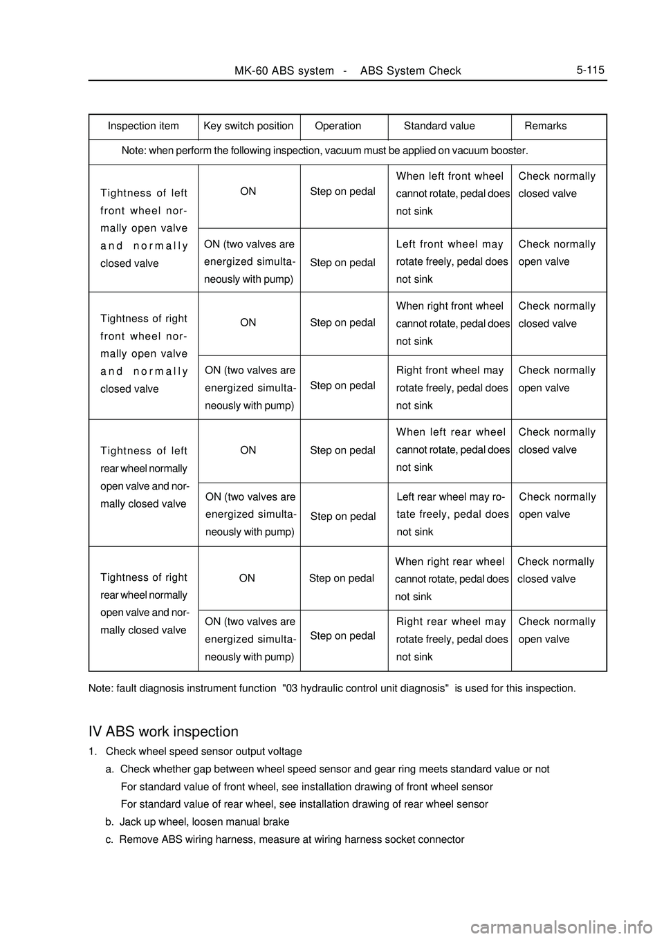
Inspection item
Note: when perform the following inspection, vacuum must be applied on vacuum booster.Tightness of left
front wheel nor-
mally open valve
and normally
closed valveON
ON (two valves are
energized simulta-
neously with pump)Step on pedal
Step on pedalWhen left front wheel
cannot rotate, pedal does
not sinkCheck normally
closed valve
Left front wheel may
rotate freely, pedal does
not sinkCheck normally
open valveTightness of right
front wheel nor-
mally open valve
and normally
closed valveON
ON (two valves are
energized simulta-
neously with pump)Step on pedal
Step on pedalWhen right front wheel
cannot rotate, pedal does
not sinkCheck normally
closed valve
Right front wheel may
rotate freely, pedal does
not sinkCheck normally
open valveTightness of left
rear wheel normally
open valve and nor-
mally closed valveON
ON (two valves are
energized simulta-
neously with pump)Step on pedal
Step on pedalWhen left rear wheel
cannot rotate, pedal does
not sinkCheck normally
closed valve
Left rear wheel may ro-
tate freely, pedal does
not sinkCheck normally
open valveTightness of right
rear wheel normally
open valve and nor-
mally closed valveON
ON (two valves are
energized simulta-
neously with pump)Step on pedal
Step on pedalWhen right rear wheel
cannot rotate, pedal does
not sinkCheck normally
closed valve
Right rear wheel may
rotate freely, pedal does
not sinkCheck normally
open valve
Note: fault diagnosis instrument function "03 hydraulic control unit diagnosis" is used for this inspection.MK-60 ABS system -ABS System Check5-115Key switch position Operation Standard value RemarksIV ABS work inspection1. Check wheel speed sensor output voltage
a. Check whether gap between wheel speed sensor and gear ring meets standard value or not
For standard value of front wheel, see installation drawing of front wheel sensor
For standard value of rear wheel, see installation drawing of rear wheel sensor
b. Jack up wheel, loosen manual brake
c. Remove ABS wiring harness, measure at wiring harness socket connector
Page 305 of 416

V. Reinstallation of ABS assemblyNote: plug of hydraulic opening on ABS assembly may be removed only when brake hard tube is to be installed,
so as to avoid foreign body entering brake system
1. Mount ABS assembly to bracket and tighten it, moment is 20~24 N.m.
2. Remove the plug on hydraulic opening, mount brake hard tube, confirm that hard tube connection is correct.
3. Mount brake hard tube to master cylinder.
4. Tightening moment for assembly of brake hard tube is 12~16N.m (M10 x 1) and 15~18 N.m (M12 x 1).
5. Fill new brake fluid into tank until liquid level reaches MAX place, use specified method to exhaust.
6. Turn ignition switch to ON, ABS warning lamp must illuminate for 1. 7s, then go out.
7. Eliminate fault code memory, reread to see whether there is any fault code.
8. Finally, run the vehicle in actual situation to confirm function of ABS (you should feel rebound of pedal).VI. ECU codeNote: when replacing HECU or ECU, encode new ECU, otherwise ABS warning lamp blinks, system can not work
normally.
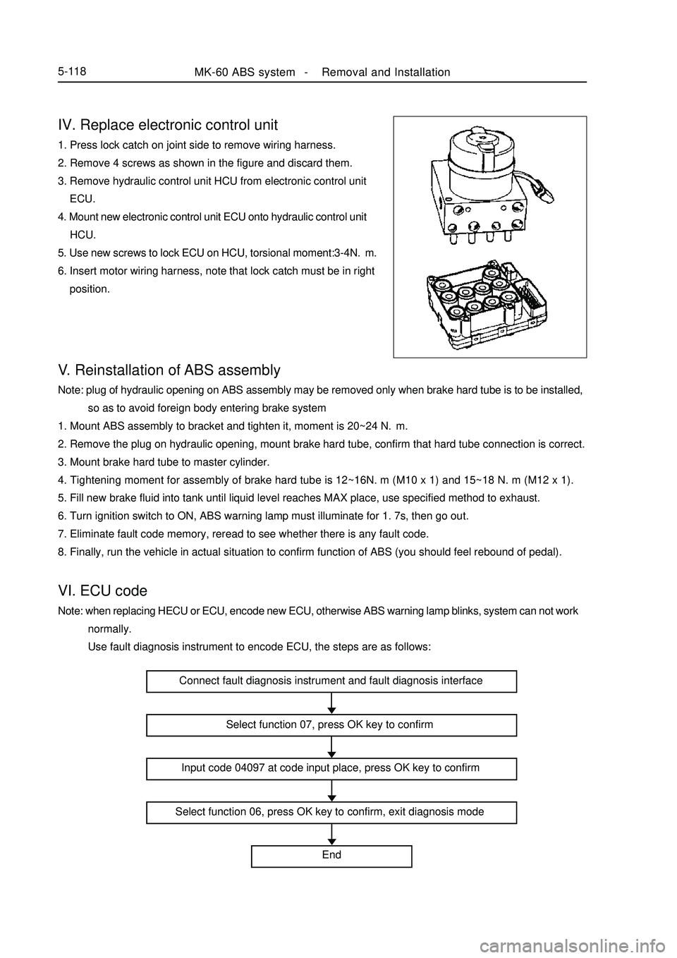
Use fault diagnosis instrument to encode ECU, the steps are as follows:IV. Replace electronic control unit1. Press lock catch on joint side to remove wiring harness.
2. Remove 4 screws as shown in the figure and discard them.
3. Remove hydraulic control unit HCU from electronic control unit
ECU.
4. Mount new electronic control unit ECU onto hydraulic control unit
HCU.
5. Use new screws to lock ECU on HCU, torsional moment:3-4N.m.
6. Insert motor wiring harness, note that lock catch must be in right
position.MK-60 ABS system -Removal and Installation5-118Connect fault diagnosis instrument and fault diagnosis interface
Select function 07, press OK key to confirm
Input code 04097 at code input place, press OK key to confirm
Select function 06, press OK key to confirm, exit diagnosis mode
End
Page 306 of 416

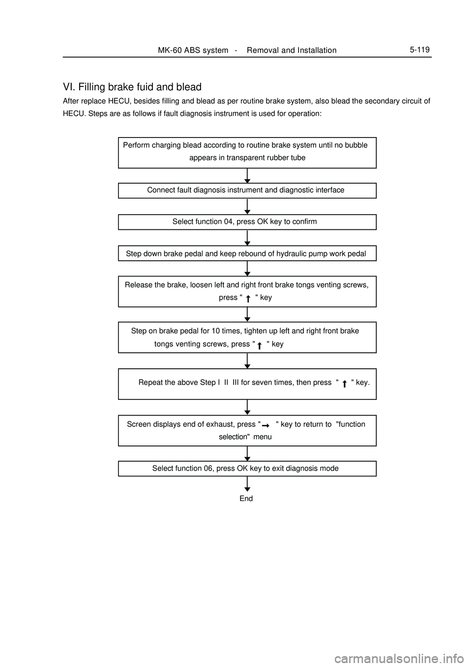
VI. Filling brake fuid and bleadAfter replace HECU, besides filling and blead as per routine brake system, also blead the secondary circuit of
HECU. Steps are as follows if fault diagnosis instrument is used for operation:MK-60 ABS system -Removal and Installation5-119Perform charging blead according to routine brake system until no bubble
appears in transparent rubber tube
Connect fault diagnosis instrument and diagnostic interface
Select function 04, press OK key to confirm
Step down brake pedal and keep rebound of hydraulic pump work pedal
Release the brake, loosen left and right front brake tongs venting screws,
press " " key
Step on brake pedal for 10 times, tighten up left and right front brake
tongs venting screws, press " " key
Repeat the above Step I II III for seven times, then press " " key.
Screen displays end of exhaust, press " " key to return to "function
selection" menu
Select function 06, press OK key to exit diagnosis modeEnd
Page 316 of 416

Chapter 10 On-board Vehicle TelephoneI. Key points for use of Geely hands-free car telephone: 1. Microphone of hands-free car telephone is installed on the back of steering wheel upright column, away from
driver to ensure talking effect. During talking, do not open window, otherwise noisy wind might influence talking
effect.
2. Since there are many kinds of mobile phones in Chinese market, in order to ensure talking effect, please
select interface line corresponding to your mobile phone, otherwise talking effect might be influenced. At present,
Nokia, Motorola, Siemens interface lines are available.
3. To use, insert one end of mobile phone interface line into 8 core RJ 45 stand on automobile panel, connect
the other end to earphone output port of the mobile phone. When mobile phone is not connected, automobile sound
works normally, when mobile phone receive a call, CD becomes quiet automatically, at the same time, loudspeaker
in the vehicle is switched to hands-free telephone output. This hands-free car telephone is provided with response
button at the top of microphone, however, new style of mobile phone does not support manual response function
for the time being, while supports automatic response function, namely it receive the call automatically after
ringing for three times.
4. After talking is finished, automobile sound will return to original state automatically.
5. During daily use, note that contact insertion and withdraw force of mobile phone interface line should not
be too large, so as to avoid damage.
6. Hands-free car telephone has no volume switch, volume of loudspeaker voice may be adjusted by regulating
the volume of handset earphone.II. Circuit diagram5-129On Board Vehicle Telephone-On-board Vehicle TelephonePlease Refer to "MK WIRING DIAGRAM"
Page 320 of 416

Centralized Controller System-
Function Inspectior5-133Chapter 12 Centralized Controller SystemSection 1 Function InspectiorI. Glass frame riser: 1. Glass frame riser may be operated to move within 60s after ignition switch is turned on or off; 60s after
ignition switch is turned off, glass frame riser cannot be operated to move;
2. Manual rise: press corresponding glass frame riser switch rise key, corresponding glass frame riser motor
works, glass frame rises, release rise key, it stops.
3. Manual fall: press corresponding glass frame riser switch fall key (hold time 300ms), corresponding glass
frame riser motor works, glass frame falls, release fall key, it stops.
4. Automatic fall: press corresponding glass frame riser switch fall key (hold time < 300 ms), corresponding
glass frame riser motor works, glass frame falls down to end; or fall down until rise key or fall key is pressed again.
Note:
During automatic fall of glass frame, if corresponding glass frame riser switch fall key is pressed down for more
than 300 ms, glass frame riser is changed to manual fall mode; if corresponding glass frame riser switch rise key
is pressed down for more than 300ms, glass frame riser stops work.
5. Remote window closing:
In case of remote protection, if a key is pressed down for more than 1s, perform glass frame riser automatic
rise action, left front, right front, left rear, right rear in turn.II. Central lock: 1. In case protection is deactivated, use a key to open left front door switch or press internal unlock switch to
open four door fasteners; close left front door switch, close four door fasteners.
2. Remote unlock /lock:
(1) Ignition switch opening
a. Press remote control unlock key to open four door fasteners;
b. Press remote lock key to close four door fasteners;
(2) Turn off ignition switch
a. Press remote unlock key to open four front door fasteners, at the same time turn light flashes once.
b. Press remote lock key to close four door fasteners, at the same time turn light flashes twice.
(3) When door is opened, press remote fastener, turn light will flash for three times, at the same time electric
horn beeps for three times.
(4) If the system is triggered in anti-theft condition, when remote unlock system exits protection state,
directional turn signal will flash for four times, at the same time, electric horn beeps for four times.
3. Automatic lock
When vehicle speed exceeds 30km/h, three doors will be closed.
4. Door lock priority
Central door lock should not act simultaneously with glass frame riser; when they conflict with each other,
central door lock acts with priority, while glass frame riser stops; after central door lock action is finished, glass
frame riser continue its work in previous condition.III. Front womdscreem wiper: After spray water signal is finished, the wiper acts twice.
Page 321 of 416

IV. Post-defrost: 1. When engine speed exceeds 700rpm (ignition switch is turned on), defrost work is permitted.
2. Turn on defrost switch, perform defrost work for 12 minutes, if defrost switch is pressed down again during
defrost work, defrost work will stop.
3. During defrost, turn off ignition switch, cancel this defrost.V. Light control: 1. Headlight:
(1) After press remote lock key to close four doors, if remote lock key is pressed down again twice in
succession within in 2s, dipped headlight will extend lighting for 1 minute; if remote unlock key is
pressed down within 60s, dipped headlight control output will be turned off.
(2) During output of 60s low level, if ignition switch is turned on, low level output will stop.
2. Ceiling lamp:
(1) When any of the doors is opened, ceiling lamp illuminates; if door is not closed, ceiling lamp will be
turned off after 10 minutes of delay.
(2) For closing of all doors, ceiling lamp will go out after time delay of 30s;
(3) In case all doors are closed,and ceiling lamp illuminates,ignition switch is turned on,ceiling lamp goes
out.
(4) For remote unlock, ceiling lamp illuminates; in case all doors are closed and ceiling lamp illuminates,
remote lock ceiling lamp goes out.VI. Remote anti-theft 1. Protected state: press lock key on remote controller, while closing four doors, anti-theft indicator lamp will
flashes slowly, indicating that the system enters protected state, when the system is triggered, turn light of the
vehicle will flash, warning horn gives out alarm.
2. Cancel protection: press unlock key on remote controller, while opening left front door, anti-theft indicator
lamp flashes rapidly, if at least one of ignition switch, door is opened within 30 s, anti-theft indicator lamp will
go out; otherwise it will enter secondary anti-theft state.
3. Two stage type protection cancellation: while the system is in triggered state, press any key on the remote
controller, alarm sound will stop, however, the system is still in protected state, and car door is still locked; if the
system continues to receive invasion signal, alarm will ring again after brief stop. To cancel protection completely,
cancel alarm for the first time, then press unlock key once immediately;
4. Secondary anti-theft: after protection is cancelled, if any of ignition switch, door is not opened within 30s,
the system will restore alert status automatically, and lock the car door.
Distribution of centralized controller connector terminals:
Connector on wiring harness, as shown in the figure below (view from outgoing terminal):Centralized Controller System-
Function Inspectior5-134Centralized
controller
Page 325 of 416

Chapter 13 Door Glass Regulating and Power Door Lock ControlSection 1 Door Glass Regulating SystemI. Inspection1. Check basic function
(1) Ignition switch is turned "ON" or within 60 s after ignition switch is turned off.
a. Check when rise key of glass regulator switch is pressed, corresponding glass rises, when release, it stops
rising; when press fall key and hold it, corresponding glass falls, when release, it stops falling.
b. Check when glass regulator main control switch lock switch on driver side is pressed,except which on driver
side, other glass regulator switches do not act.
c. Automatic fall: press corresponding glass regulator switch fall key briefly,corresponding glass
regulator motor works, glass falls down to the end; or falls down until rise key or fall key is pressed again.
Notes:
During automatic glass down, if corresponding glass regulator switch fall key is pressed down and held,
glass regulator is changed into manual fall mode; if corresponding glass regulator switch rise key is pressed down
and held, glass regulator is changed into manual rise mode; if corresponding glass regulator switch rise or fall key
is pressed briefly, glass regulator stops work. Press briefly: less than 300ms; press and hold: more than 300 ms.
(2) Close window remotely.
In case setting protection remotely, if a key is pressed for more than 1s, glass regulator automatic window
rising action will be performed, implementation mode: left front, right front, left rear, right back, in the
process of window rise, only one glass regulator is permitted to act, only after glass regulator up to the top,
could the other glass riser act.
2. Glass reguelator switch on driver sideDoor Glass Regulating and Power Door Lock Control-Door Glass Regulating System5-136Glass regulator switch on driver side
Window on front passenger side
Window on driver side
Rear right window
Rear left window
Window locking switch
Page 329 of 416

2. Check door lock main control switch (1) Connection of terminals
Standard:Section 2 Power Door Lock Control SystemI. Inspection1. Check basic function
a. When door lock control switch locks, four door locks are locked; when door lock control switch unlocks,
four doors are unlocked.
b. When door lock on driver side is locked using key, four door locks are locked.Terminal No. Door lock state Standard state
12-7 Lock ON
- OFF OFF
12-15 Unlock ONMeasuring condition
Battery positive -1
Battery negative -2
Battery positive -1
Battery negative -2Door Glass Regulating and Power Door Lock Control-
Power Door Lock Control System5-142 If it does not meet stipulation, replace this switch.
3. Fastener inspection
(1)Apply storage battery voltage, check operation of the actuator.
Standard:
If not, replace actuator assembly.Standard state
Unlock
LockLOCKUnlock
Power door lock center control switchBatteryLock
Unlock