steering GEELY MK 2008 Owner's Manual
[x] Cancel search | Manufacturer: GEELY, Model Year: 2008, Model line: MK, Model: GEELY MK 2008Pages: 416, PDF Size: 25.19 MB
Page 48 of 416

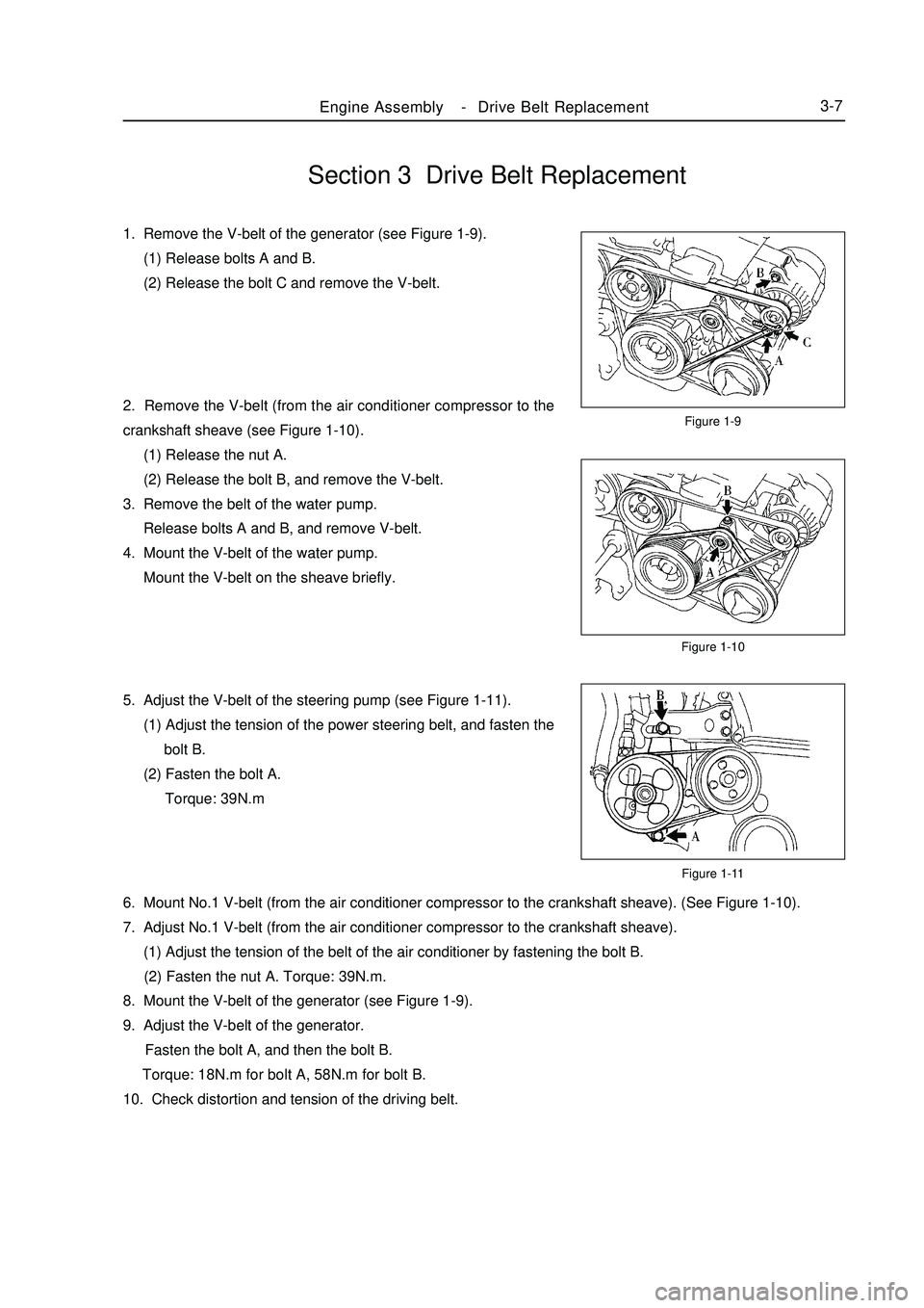
Section 3 Drive Belt Replacement1. Remove the V-belt of the generator (see Figure 1-9).
(1) Release bolts A and B.
(2) Release the bolt C and remove the V-belt.
2. Remove the V-belt (from the air conditioner compressor to the
crankshaft sheave (see Figure 1-10).
(1) Release the nut A.
(2) Release the bolt B, and remove the V-belt.
3. Remove the belt of the water pump.
Release bolts A and B, and remove V-belt.
4. Mount the V-belt of the water pump.
Mount the V-belt on the sheave briefly.
5. Adjust the V-belt of the steering pump (see Figure 1-11).
(1) Adjust the tension of the power steering belt, and fasten the
bolt B.
(2) Fasten the bolt A.
Torque: 39N.mFigure 1-9
Figure 1-10
Figure 1-11Engine AssemblyDrive Belt Replacement3-76. Mount No.1 V-belt (from the air conditioner compressor to the crankshaft sheave). (See Figure 1-10).
7. Adjust No.1 V-belt (from the air conditioner compressor to the crankshaft sheave).
(1) Adjust the tension of the belt of the air conditioner by fastening the bolt B.
(2) Fasten the nut A. Torque: 39N.m.
8. Mount the V-belt of the generator (see Figure 1-9).
9. Adjust the V-belt of the generator.
Fasten the bolt A, and then the bolt B.
Torque: 18N.m for bolt A, 58N.m for bolt B.
10. Check distortion and tension of the driving belt. -
Page 50 of 416

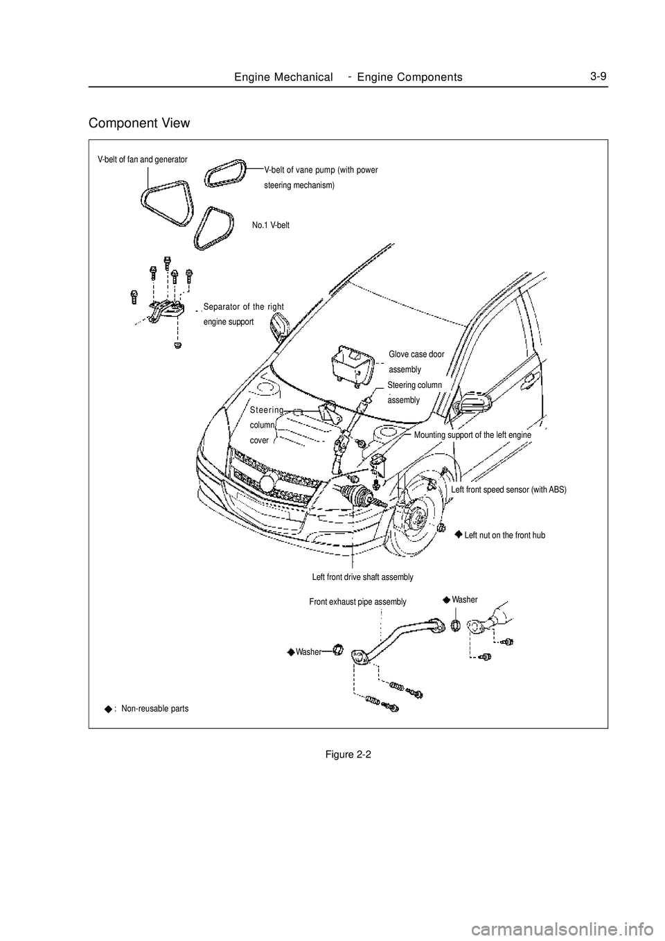
Component ViewFigure 2-2Engine MechanicalEngine Components3-9V-belt of fan and generator
V-belt of vane pump (with power
steering mechanism)
No.1 V-belt
Glove case door
assemblyFront exhaust pipe assemblySeparator of the right
engine support: Non-reusable partsLeft front drive shaft assemblyLeft nut on the front hubSteering
column
coverSteering column
assembly
Mounting support of the left engineLeft front speed sensor (with ABS)
Washer
Washer -
Page 51 of 416

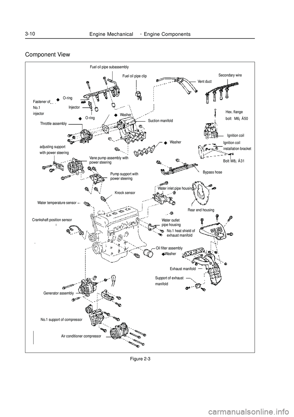
Component ViewFigure 2-3Engine MechanicalEngine Components3-10adjusting support
with power steering
Vane pump assembly with
power steering
Pump support with
power steeringHex. flange
bolt M6¡Á50
Ignition coil
Ignition coilinstallation bracket
Bolt M8¡Á31Fuel oil pipe subassembly
Fuel oil pipe clip
Vent ductSecondary wireBypass hose
Rear end housingWater outlet
pipe housing
No.1 heat shield of
exhaust manifoldOil filter assembly
Washer
Exhaust manifold
Support of exhaust
manifoldO-ring
Fastener of
No.1
injectorInjector
O-ring
Throttle assemblySuction manifold Washer
WasherKnock sensor
Water temperature sensorCrankshaft position sensorGenerator assemblyNo.1 support of compressor
Air conditioner compressorWater inlet pipe housing -
Page 52 of 416

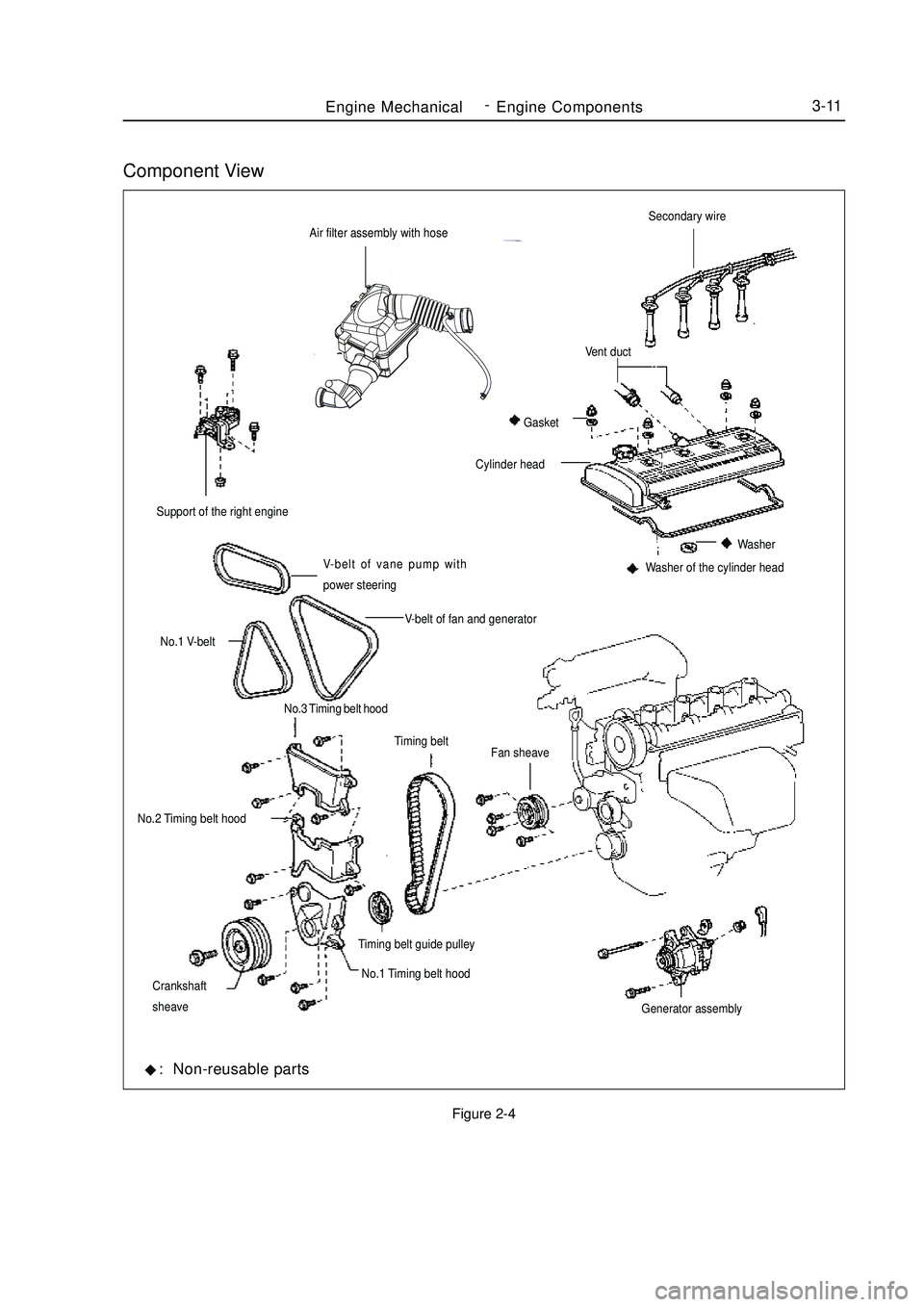
Component ViewFigure 2-4Air filter assembly with hoseEngine MechanicalEngine Components3-11V-belt of vane pump with
power steering Support of the right engine
V-belt of fan and generator
No.1 V-belt
No.3 Timing belt hood
No.2 Timing belt hood
No.1 Timing belt hoodFan sheaveSecondary wireWasher of the cylinder headCylinder headVent duct
Gasket
Washer
Timing belt
Timing belt guide pulley
Crankshaft
sheave
Generator assembly: Non-reusable parts -
Page 94 of 416

Chapter 4 Propeller Shaft/DriveshaftSection 1 Propeller Shaft, Driveshaft and TransaxleI. Symptom Table The table below can help find the causes of the problem. The numbers indicate the priority of the causes of the
problem. Replace the parts if necessary.
Inspection Area
1. Wheel
2. Front wheel alignment
3. Rear wheel alignment
4. Front wheel hub bearing (worn)
5. Rear wheel hub bearing (worn)
6. Front shock absorber with coil spring
7. Steering linkage (loose or damaged)
8. Stabilizer bar
1. Wheel balance
2. Wheel hub bearing (worn)
3. Front shock absorber with coil spring
1. Outer joint (worn)
2. Inner joint (worn) Symptom
Deviation
Front wheel vibration
Noise (drive shaft)ReferenceII. On-board Inspection1. Check front wheel hub bearing
(1) Remove front wheel.
(2) Remove front brake caliper assembly.
(3) Remove front brake disc.
(4) Check the bearing backlash.
Set a dial indicator near the front wheel hub center to check
the backlash.
Maximum: 0.05mm
If the backlash exceeds the maximum value, replace the front
wheel hub bearing.
(5) Check the front wheel hub deviation
Using a dial indicator, check the deviation of the surface of the
wheel hub outside the hub bolt.
Maximum: 0.07mm
If the backlash exceeds the maximum value, replace the front
wheel hub subassembly.Propeller Shaft/DriveshaftPropeller Shaft, Driveshaft and Transaxle4-17 -
Page 98 of 416

Overhaul1. Drain manual transmission oil (M/T transmission)
Torque: 39N.m
2. Drain automatic transmission oil (A/T transmission)
Torque: 25N.m
3. Remove front wheel
4. Remove engine bottom left shield (M/T transaxle)
5. Remove engine bottom right shield (M/T transaxle)
6. Remove engine bottom shield assembly (A/T transaxle)
7. Remove front wheel hub left bolt
(1) Using a hammer and a drive shaft nut chisel, unstake the
staked part of the left wheel hub nut.
(2) While applying the brake pedal, remove the left wheel hub
nut.
Notice: the staked part of the nut should be fully unstaked,
otherwise it may damage the thread of the drive shaft.
8. Remove left front vehicle speed sensor (with ABS)
(1) Remove the bolt and clip, remove vehicle speed sensor and
brake hose from left front shock absorber assembly.
(2) Remove the bolt, separate the left front vehicle speed sensor
from steering knuckle.
9. Remove front stabilizer bar
(1) Use a 10mm wrench to hold the bolt, remove the nut
(2) Remove two collars, No.1 and No.2 gaskets, remove front
stabilizer barPropeller Shaft/DriveshaftFront Driveshaft4-21 -
Page 99 of 416

10. Separate left lower swing arm assembly
(1) Remove cotter pin and nut
(2) On steering knuckle, remove the left lower swing arm
assembly with ball joint puller.
11. Separate steering gear with tie rod assembly
(1) Remove cotter pin and nut
(2) On steering knuckle, remove the steering gear with tie rod
assembly with ball joint puller.Propeller Shaft/DriveshaftFront Driveshaft4-2212. Separate LF steering knuckle assembly
Using a plastic hamper, separate left front drive shaft assembly from left front steering knuckle assembly
Notice:
Do not damage the boot.
With ABS:
Be careful not to damage the vehicle speed sensor rotor.
13. Remove left constant velocity drive shaft assembly
Using a differential side gear shaft remover, remove the left
constant velocity drive shaft assembly.
Notice:
Do not damage the boot and oil seal.
Be careful not to drop the drive shaft assembly.
14. Remove right constant velocity drive shaft assembly
Using a brass bar and a hammer, remove the right constant
velocity drive shaft assembly.
Notice:
Do not damage the boot and oil seal.
Be careful not to drop the drive shaft assembly. -
Page 100 of 416

15. Install LF steering knuckle assembly
Notice:
The hub bearing could be damaged if it is subjected to the vehicle
weight, such as when moving the vehicle with the drive shaft
bearing removed.
Therefore if it is absolutely necessary to place the vehicle weight
on the hub bearing, first support it with the special service tool for
front hub bearing.
16. Check left constant velocity drive shaft assembly
(1) Check the outboard joint for apparent looseness.
(2) Check that the inboard joint slide smoothly.
(3) Check the inboard joint for radial looseness.
(4) Check the boot for damage.
Notice:
Place the drive shaft assembly on level surface during the
inspection.
17. Remove inboard joint big clamp
Using a screw driver, loosen the inboard joint big clamp.
18. Remove inboard joint small clamp
Using a screw driver, loosen the inboard joint small clamp.
19. Separate inboard joint boot
Separate the outboard joint boot from the outboard Rzeppa joint
assembly.
20. Remove left tripod joint assembly
(1) Wipe off the old grease from the tripod joint assembly.
(2) Place the matchmarks between the tripod joint assembly and
the outboard Rzeppa joint.
Notice:
Do not punch the matchmarks.Propeller Shaft/DriveshaftFront Driveshaft4-23Mark -
Page 105 of 416

Propeller Shaft/DriveshaftFront Driveshaft4-28 Hint:
Please refer to the following table for dimension (A).LH mm
528.3±5.0
527.0±5.0RH mm
859.3±5.0
860.0±5.0 M/T manual transmission
A/T automatic transmission38. Install left constant velocity drive shaft assembly
(1) M/T
Coat the spline of the tripod joint assembly with gear oil.
(2) A/T
Coat the spline of the tripod joint assembly with ATF
(Automatic Transmission Fluid).
(3) Align the spline, use a brass bar and hammer to install the left
drive shaft assembly.
Notice:
Face the retainer open end downward.
Be careful not to damage the boot and oil seal.
Hint:
You can find out whether the tripod joint shaft contact the pinion shaft by rotating the shaft assembly, listening
to the sound and feeling.
39. Install right constant velocity drive shaft assembly
Hint:
The installation of the right side is the same as that of the left side.
Notice:
Install the retainer with its open end facing downward.
Be careful not to damage the boot and oil seal.
40. Install left steering knuckle assembly
Install the left constant velocity drive shaft assembly on the left steering knuckle assembly.
Notice:
Be careful not to damage the outboard joint boot.
With ABS:
Be careful not to damage the vehicle speed sensor rotor.
41. Install left steering gear with tie rod assembly
(1) Install the steering gear with tie rod assembly on the steering knuckle assembly with nuts.
Torque: 33N.m
(2) Install the new cotter pins.
Notice:
If the pin holes are not aligned, further tighten the nut by 60°.
42. Install left lower swing arm assembly
(1) Install the left lower swing arm assembly on the steering knuckle assembly with nuts.
Torque: 98N.m -
Page 106 of 416

Propeller Shaft/DriveshaftFront Driveshaft4-29 (2) Install the new cotter pins.
Notice:
If the pin holes are not aligned, further tighten the nut by 60°.
43. Install front stabilizer bar
(1) As shown in the illustration, install the stabilizer bar with two
No.1 collars and two gaskets and nuts.
Notice:
Make sure the gaskets and collars are correctly installed.
(2) Tighten the nut with a 10mm wrench.
Torque: 18N.m
44. Install left front vehicle speed sensor (with ABS)
(1) Install the left front vehicle speed sensor and brake hose on the
front shock absorber with bolts and clps.
Torque: 29N.m
(2) Install the vehicle speed sensor on the steering knuckle with
bolts.
Torque: 8.0N.m
Notice:
Be careful not to damage the wheel speed sensor.
Keep the vehicle speed sensor clean.
When installing the sensor,do not twist the sensor wire harness.
45. Install left steering knuckle wheel hub nut
(1) Install new left steering knuckle hub nuts
Torque: 216N.m
(2) Using a chisel and hammer, stake the hub locking nut.
46. Install engine bottom left shield
47. Install engine bottom right shield
48. Install engine bottom shield assembly
49. Install front wheel
Torque: 103 N.m
50. Add oil into manual transmission
51. Check and adjust the manual transmission fluid
52. Refill automatic transmission fluid
53. Check and adjust the automatic transmission fluid
54. Check and adjust front wheel alignment
55. Check ABS vehicle speed signal (with ABS) -