check oil GEELY MK 2008 Service Manual
[x] Cancel search | Manufacturer: GEELY, Model Year: 2008, Model line: MK, Model: GEELY MK 2008Pages: 416, PDF Size: 25.19 MB
Page 206 of 416
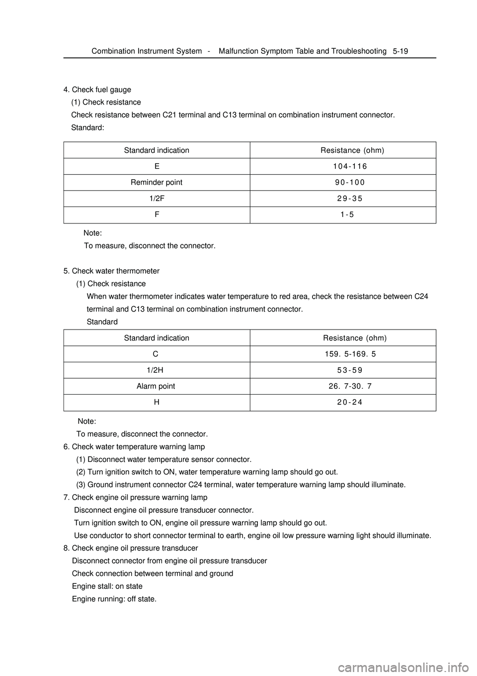
Note:
To measure, disconnect the connector.
5. Check water thermometer
(1) Check resistance
When water thermometer indicates water temperature to red area, check the resistance between C24
terminal and C13 terminal on combination instrument connector.
Standard 4. Check fuel gauge
(1) Check resistance
Check resistance between C21 terminal and C13 terminal on combination instrument connector.
Standard:5-19Standard indication
E
Reminder point
1/2F
FResistance (ohm)
104-116
90-100
29-35
1-5
Standard indication
C
1/2H
Alarm point
HResistance (ohm)
159. 5-169. 5
53-59
26. 7-30. 7
20-24
Note:
To measure, disconnect the connector.
6. Check water temperature warning lamp
(1) Disconnect water temperature sensor connector.
(2) Turn ignition switch to ON, water temperature warning lamp should go out.
(3) Ground instrument connector C24 terminal, water temperature warning lamp should illuminate.
7. Check engine oil pressure warning lamp
Disconnect engine oil pressure transducer connector.
Turn ignition switch to ON, engine oil pressure warning lamp should go out.
Use conductor to short connector terminal to earth, engine oil low pressure warning light should illuminate.
8. Check engine oil pressure transducer
Disconnect connector from engine oil pressure transducer
Check connection between terminal and ground
Engine stall: on state
Engine running: off state.Combination Instrument System -Malfunction Symptom Table and Troubleshooting
Page 211 of 416
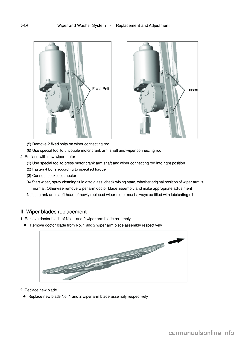
Fixed Bolt (5) Remove 2 fixed bolts on wiper connecting rod
(6) Use special tool to uncouple motor crank arm shaft and wiper connecting rod
2. Replace with new wiper motor
(1) Use special tool to press motor crank arm shaft and wiper connecting rod into right position
(2) Fasten 4 bolts according to specified torque
(3) Connect socket connector
(4) Start wiper, spray cleaning fluid onto glass, check wiping state, whether original position of wiper arm is
normal, Otherwise remove wiper arm doctor blade assembly and make appropriate adjustment
Notes: crank arm shaft head of newly replaced wiper motor must always be filled with lubricating oilII. Wiper blades replacement1. Remove doctor blade of No. 1 and 2 wiper arm blade assembly
Remove doctor blade from No. 1 and 2 wiper arm blade assembly respectivelyLoosenWiper and Washer System -Replacement and Adjustment5-242. Replace new blade
Replace new blade No. 1 and 2 wiper arm blade assembly respectively
Page 250 of 416
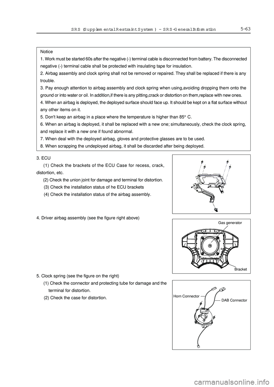
5-633. ECU
(1) Check the brackets of the ECU Case for recess, crack,
distortion, etc.
(2) Check the union joint for damage and terminal for distortion.
(3) Check the installation status of he ECU brackets
(4) Check the installation status of the airbag assembly.Notice
1. Work must be started 60s after the negative (-) terminal cable is disconnected from battery. The disconnected
negative (-) terminal cable shall be protected with insulating tape for insulation.
2. Airbag assembly and clock spring shall not be removed or repaired. They shall be replaced if there is any
trouble.
3. Pay enough attention to airbag assembly and clock spring when using,avoiding dropping them onto the
ground or into water or oil. In addition,if there is any pitting,crack or distortion on them,replace with new ones.
4. When an airbag is deployed, the deployed surface should face up. It should be kept on a flat surface without
any other items on it.
5. Don't keep an airbag in a place where the temperature is higher than 85°C.
6. When an airbag is deployed, it shall be replaced with a new one; simultaneously, check the clock spring,
and replace it with a new one if found abnormal.
7. When deal with the deployed airbag, gloves and protective glasses are to be used.
8. When scrapping the undeployed airbag, it shall be discarded after being deployed.Bracket Gas generatorDAB ConnectorHorn ConnectorSRS (Supplemental Restraint System)-SRS-General Information4. Driver airbag assembly (see the figure right above)
5. Clock spring (see the figure on the right)
(1) Check the connector and protecting tube for damage and the
terminal for distortion.
(2) Check the case for distortion.
Page 260 of 416
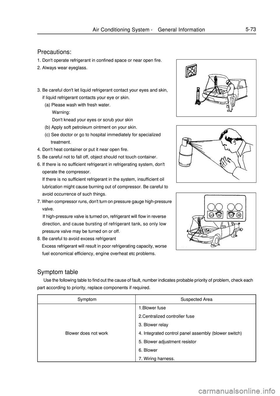
5-73Precautions:1. Don't operate refrigerant in confined space or near open fire.
2. Always wear eyeglass.
3. Be careful don't let liquid refrigerant contact your eyes and skin,
if liquid refrigerant contacts your eye or skin.
(a) Please wash with fresh water.
Warning:
Don't knead your eyes or scrub your skin
(b) Apply soft petroleum ointment on your skin.
(c) See doctor or go to hospital immediately for specialized
treatment.
4. Don't heat container or put it near open fire.
5. Be careful not to fall off, object should not touch container.
6. If there is no sufficient refrigerant in refrigerating system, don't
operate the compressor.
If there is no sufficient refrigerant in the system, insufficient oil
lubrication might cause burning out of compressor. Be careful to
avoid occurrence of such things.
7. When compressor runs, don't turn on pressure gauge high-pressure
valve.
If high-pressure valve is turned on, refrigerant will flow in reverse
direction, and cause bursting of refrigerant tank, so only low
pressure valve may be turned on or off.
8. Be careful to avoid excess refrigerant
Excess refrigerant will result in poor refrigerating capacity, worse
fuel economical efficiency, engine overheat etc problems.Symptom
Blower does not workSymptom table Use the following table to find out the cause of fault, number indicates probable priority of problem, check each
part according to priority, replace components if required.
Suspected Area
1.Blower fuse
2.Centralized controller fuse
3. Blower relay
4. Integrated control panel assembly (blower switch)
5. Blower adjustment resistor
6. Blower
7. Wiring harness.Air Conditioning System -General Information
Page 268 of 416
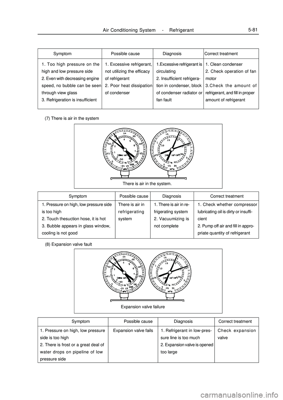
Air Conditioning System -Refrigerant5-811. Too high pressure on the
high and low pressure side
2. Even with decreasing engine
speed, no bubble can be seen
through view glass
3. Refrigeration is insufficient1. Excessive refrigerant,
not utilizing the efficacy
of refrigerant
2. Poor heat dissipation
of condenser1.Excessive refrigerant is
circulating
2. Insufficient refrigera-
tion in condenser, block
of condenser radiator or
fan fault1. Clean condenser
2. Check operation of fan
motor
3.Check the amount of
refrigerant, and fill in proper
amount of refrigerant1. Pressure on high, low pressure side
is too high
2. Touch thesuction hose, it is hot
3. Bubble appears in glass window,
cooling is not goodThere is air in
refrigerating
system1. There is air in re-
frigerating system
2. Vacuumizing is
not complete1. Check whether compressor
lubricating oil is dirty or insuffi-
cient
2. Pump off air and fill in appro-
priate quantity of refrigerantThere is air in the system. (7) There is air in the system (8) Expansion valve fault1. Pressure on high, low pressure
side is too high
2. There is frost or a great deal of
water drops on pipeline of low
pressure sideRefrigerant in low-pres-
sure line is too much
2. Expansion valve is opened
too largeCheck expansion
valveExpansion valve failureSymptom Possible cause Diagnosis Correct treatment
Symptom Possible cause Diagnosis Correct treatment Symptom Possible cause Diagnosis Correct treatment
Expansion valve fails1.
Page 291 of 416
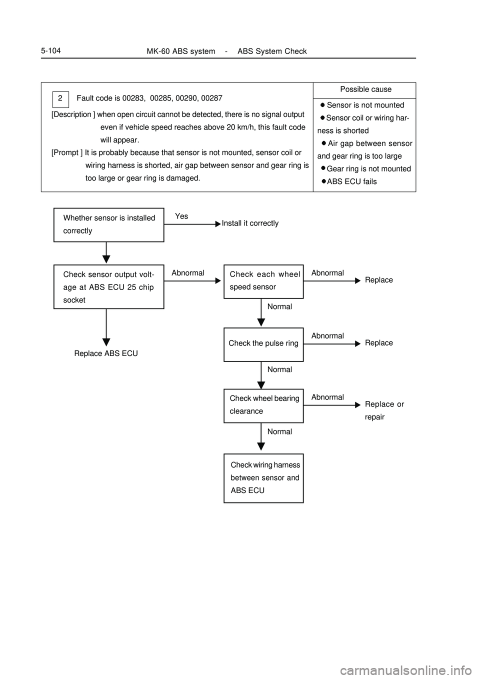
Whether sensor is installed
correctlyYes
Install it correctlyCheck sensor output volt-
age at ABS ECU 25 chip
socketAbnormal
ReplaceCheck each wheel
speed sensorAbnormalReplace ABS ECUNormal
Replace or
repairCheck wheel bearing
clearanceAbnormalCheck wiring harnessbetween sensor andABS ECUNormalMK-60 ABS system -ABS System Check5-104Fault code is 00283, 00285, 00290, 00287 2
[Description ] when open circuit cannot be detected, there is no signal output
even if vehicle speed reaches above 20 km/h, this fault code
will appear.
[Prompt ] It is probably because that sensor is not mounted, sensor coil or
wiring harness is shorted, air gap between sensor and gear ring is
too large or gear ring is damaged.Possible cause
Sensor is not mounted
Sensor coil or wiring har-
ness is shorted
Air gap between sensor
and gear ring is too large
Gear ring is not mounted
ABS ECU fails
ReplaceCheck the pulse ringAbnormalNormal
Page 292 of 416
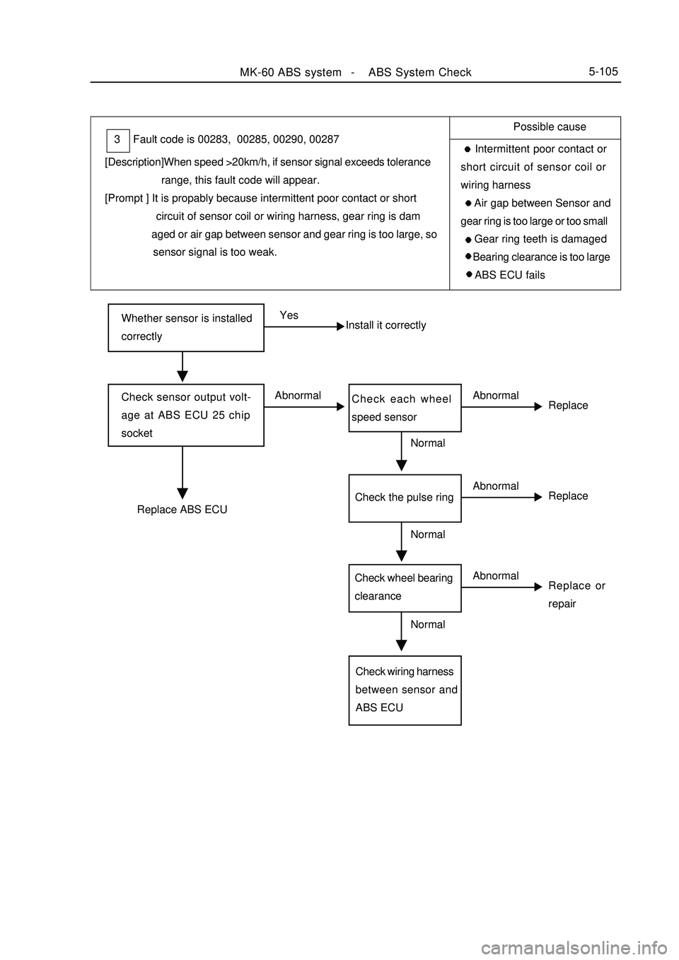
Whether sensor is installed
correctlyYes
Install it correctlyCheck sensor output volt-
age at ABS ECU 25 chip
socketAbnormal
ReplaceCheck each wheel
speed sensorReplace ABS ECUNormal
ReplaceReplace or
repairCheck wheel bearing
clearanceCheck wiring harness
between sensor and
ABS ECUNormal
NormalMK-60 ABS system -ABS System Check5-105Fault code is 00283, 00285, 00290, 00287 3
[Description]When speed >20km/h, if sensor signal exceeds tolerance
range, this fault code will appear.
[Prompt ] It is propably because intermittent poor contact or short
circuit of sensor coil or wiring harness, gear ring is dam
aged or air gap between sensor and gear ring is too large, so
sensor signal is too weak.Possible cause
Intermittent poor contact or
short circuit of sensor coil or
wiring harness
Air gap between Sensor and
gear ring is too large or too small
Gear ring teeth is damaged
Bearing clearance is too large
ABS ECU fails
Abnormal
Abnormal
Abnormal Check the pulse ring
Page 293 of 416
![GEELY MK 2008 Service Manual MK-60 ABS system -ABS System Check5-106Fault code is 00283, 00285, 00290, 00287 4
[Description]When identifiable open circuit, short circuit etc faults exist on
sensor, this fault GEELY MK 2008 Service Manual MK-60 ABS system -ABS System Check5-106Fault code is 00283, 00285, 00290, 00287 4
[Description]When identifiable open circuit, short circuit etc faults exist on
sensor, this fault](/img/58/57162/w960_57162-292.png)
MK-60 ABS system -ABS System Check5-106Fault code is 00283, 00285, 00290, 00287 4
[Description]When identifiable open circuit, short circuit etc faults exist on
sensor, this fault code will appear.
[Prompt ] It might because poor contact of sensor, short circuit of coil or
wiring harness or faulty sensor signal processing circuit in ABS
ECUPossible cause
Sensor socket connector
or coil is disconnected
Sensor coil appear is
shorted
Sensor plug or wiring har-
ness is shorted with earth or
power supply
ABS ECU sensor signal
processing circuit failsCheck sensor of each wheel
Replace ABS ECURemove ABS ECU plug, check
whether resistance value between
the following terminals conforms
to standard value or not?
Standard value : 1.0-1.3K ohm¸
Left front : 45-46
Right front :33-34
Left rear : 36-37
Left rear: 42-43Check corresponding sensor
plugWhether fault recursCheck wiring harness between ECU and sensorRefer to key point for re-
pair of occasional fault Repair socket connector
Normal
No
YesAbnormal
AbnormalNormal Normal
Page 303 of 416
Section3 Removal and InstallationI. Precautions for removal and installation1. Firstly use diagnostic instrument to find out source of trouble, then repair.
2. Repair front prior use excluding mineral oil of detergent will surface clean Neatness ; repair when should note
before repair, use detergent without mineral oil to wipe off surface; pay attention to cleaning during repair, only
use rag without wool to wipe removed components.
3. Only use original factory spare parts, and new spare parts could only be unpacked just before installation.
4. Return liquid pump motor and hydraulic controller (HCU) is integrated structure, can not be separated.MK-60 ABS system -ABS System Check/ Removal and Installation5-116 d. Rotate the wheel at speed of about 1 / 2 turns per second, use multimeter or oscillograph to measure output
voltage
Terminal 45-46
Terminal 33-34
Terminal 37-36
Terminal 42-43
Output voltage
When use multimeter for measurement
See front wheel sensor drawing for front wheel.
See rear wheel sensor drawing for rear wheel
When use oscillograph for measurement
See relevant standard for front wheel.
See relevant standard for rear wheel.
e. If output voltage is not in above-mentioned range, the cause might be the following:
Air gap between sensor and pulse ring is too large.
Sensor fails.
Check sensor resistance value (1. 0 - 1. 3 k ohm).
Take four points on pulse ring to check air gap between pulse ring and wheel speed sensor (pulse ring
distortion).
2. Check hydraulic pressure unit HCU
a. Jack up vehicle to confirm that wheel may rotate freely.
b. Release manual brake.
c. After connecting fault diagnosis instrument, turn ignition switch to ON, here it is not necessary to start up
engine.
e. Check with reference to hydraulic control unit diagnosis.
Note: when connect or remove fault diagnosis instrument, ignition switch must be in OFF position
Page 304 of 416
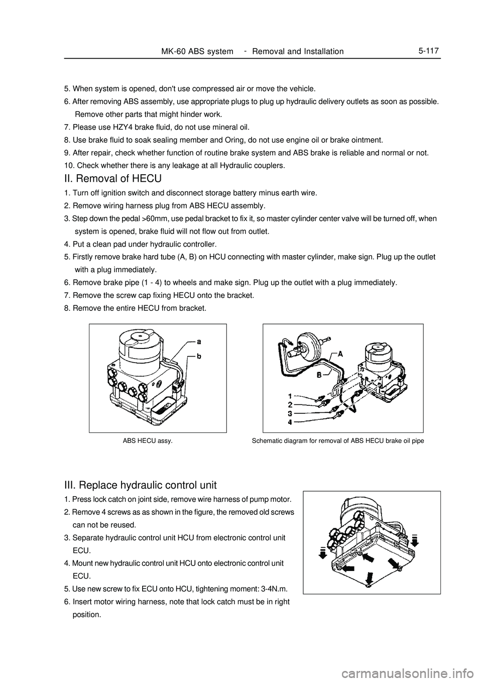
ABS HECU assy.III. Replace hydraulic control unit1. Press lock catch on joint side, remove wire harness of pump motor.
2. Remove 4 screws as as shown in the figure, the removed old screws
can not be reused.
3. Separate hydraulic control unit HCU from electronic control unit
ECU.
4. Mount new hydraulic control unit HCU onto electronic control unit
ECU.
5. Use new screw to fix ECU onto HCU, tightening moment: 3-4N.m.
6. Insert motor wiring harness, note that lock catch must be in right
position.MK-60 ABS system -
Removal and Installation5-117Schematic diagram for removal of ABS HECU brake oil pipe5. When system is opened, don't use compressed air or move the vehicle.
6. After removing ABS assembly, use appropriate plugs to plug up hydraulic delivery outlets as soon as possible.
Remove other parts that might hinder work.
7. Please use HZY4 brake fluid, do not use mineral oil.
8. Use brake fluid to soak sealing member and Oring, do not use engine oil or brake ointment.
9. After repair, check whether function of routine brake system and ABS brake is reliable and normal or not.
10. Check whether there is any leakage at all Hydraulic couplers.II. Removal of HECU1. Turn off ignition switch and disconnect storage battery minus earth wire.
2. Remove wiring harness plug from ABS HECU assembly.
3. Step down the pedal >60mm, use pedal bracket to fix it, so master cylinder center valve will be turned off, when
system is opened, brake fluid will not flow out from outlet.
4. Put a clean pad under hydraulic controller.
5. Firstly remove brake hard tube (A, B) on HCU connecting with master cylinder, make sign. Plug up the outlet
with a plug immediately.
6. Remove brake pipe (1 - 4) to wheels and make sign. Plug up the outlet with a plug immediately.
7. Remove the screw cap fixing HECU onto the bracket.
8. Remove the entire HECU from bracket.