check engine GEELY MK 2008 Repair Manual
[x] Cancel search | Manufacturer: GEELY, Model Year: 2008, Model line: MK, Model: GEELY MK 2008Pages: 416, PDF Size: 25.19 MB
Page 288 of 416

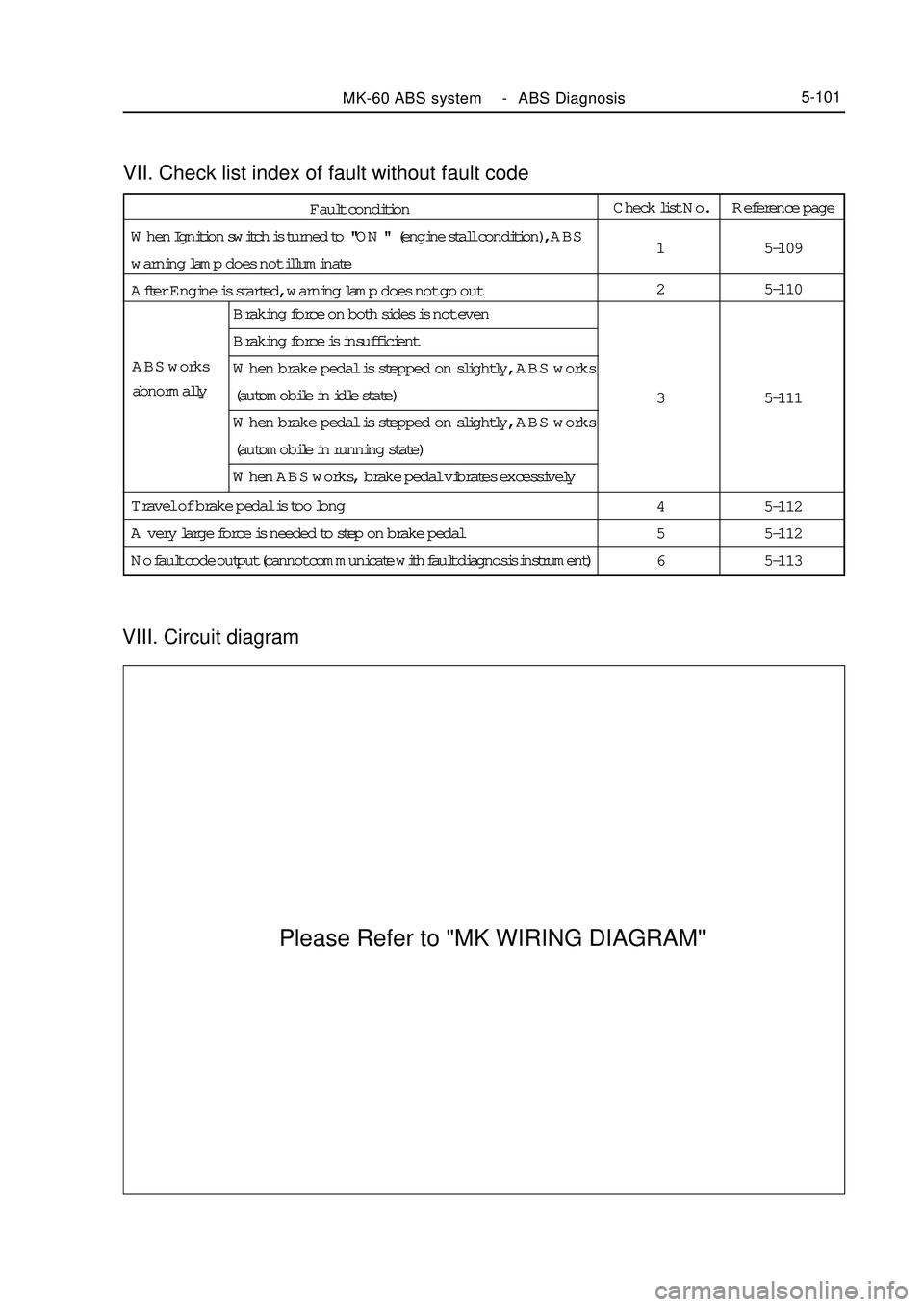
VIII. Circuit diagramVII. Check list index of fault without fault codeMK-60 ABS system -ABS Diagnosis5-101Fault condition
When Ignition switch is turned to "ON " (engine stall condition), ABS
warning lamp does not illuminate
After Engine is started, warning lamp does not go outCheck list No.
1
2
3
4
5
6Reference page
5-109
5-110
5-111
5-112
5-112
5-113 ABS works
abnormallyBraking force on both sides is not even
Braking force is insufficient
When brake pedal is stepped on slightly, ABS works
(automobile in idle state)
When brake pedal is stepped on slightly, ABS works
(automobile in running state)
When ABS works, brake pedal vibrates excessively
Travel of brake pedal is too long
A very large force is needed to step on brake pedal
No fault code output (cannot communicate with fault diagnosis instrument)Please Refer to "MK WIRING DIAGRAM"
Page 296 of 416

Check ABS warning lamp
safety wire in fuse boxCheck
ABS warning lamp safety wire
in fuse boxReplace AbnormalRemove ECU joint, when igni-
tion switch is in ON, does warn-
ing lamp illuminate ?NoNormalCheck whether ABS warn-
ing lamp is burnt outYes
ReplaceCheck whether warning
lamp power supply circuit
and ground loop in wiring
harness is disconnectedAbnormalRepair wiring
harnessCheck warning lamp power
supply circuit and ground
loop socket connector in
wiring harnessAbnormalRepair socket
connectorDoes fault reoccurNoRepair wiring harnessYe s NormalNormal NoRefer to key point
for repair of occa-
sional faultII. Check list of fault without malfunction codeMK-60 ABS system -ABS System Check5-109When ignition switch is in ON position (engine stall), ABS warning
lamp does not illuminate 1
[Description ] ABS warning lamp does not illuminate, warning lamp power
supply circuit might be disconnected, bulb is burnt out or
warning lamp driving module is damaged.Possible cause
Safety wire is burnt out
ABS warning lamp bulb
is burnt out
Power circuit is discon-
nected
ABS warning lamp driv-
ing module is damaged
YesCheck whether the wire in ABS
wiring harness connecting ABS
warning lamp driving module
and ECU is shorted to ground
Page 297 of 416

Note: this fault mode is only limited to the condition in which system may communicate with fault diagnosis
instrument (ABS ECU ABS ECU power supply is normal), and there is no fault code.MK-60 ABS system -ABS System Check5-110 After engine starts up, ABS warning lamp illuminates normally 2
[Description] Probably because ABS warning lamp driving module is
damaged or ABS warning lamp circuit is disconnected.Possible cause
ABS warning lamp driving
module is damaged
ABS warning lamp driving
module circuit is disconnected
ABS ECU is damagedCheck whether wire between
ECU and ABS warning lamp
driving module is disconnectedRepair wire harness Yes
NoCheck ABS warning lamp driv-
ing moduleReplace Abnormal
NormalReplace ABS ECU
Page 303 of 416

Section3 Removal and InstallationI. Precautions for removal and installation1. Firstly use diagnostic instrument to find out source of trouble, then repair.
2. Repair front prior use excluding mineral oil of detergent will surface clean Neatness ; repair when should note
before repair, use detergent without mineral oil to wipe off surface; pay attention to cleaning during repair, only
use rag without wool to wipe removed components.
3. Only use original factory spare parts, and new spare parts could only be unpacked just before installation.
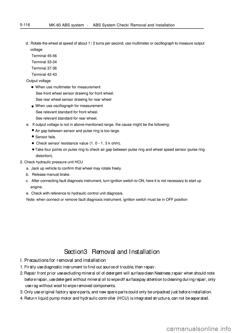
4. Return liquid pump motor and hydraulic controller (HCU) is integrated structure, can not be separated.MK-60 ABS system -ABS System Check/ Removal and Installation5-116 d. Rotate the wheel at speed of about 1 / 2 turns per second, use multimeter or oscillograph to measure output
voltage
Terminal 45-46
Terminal 33-34
Terminal 37-36
Terminal 42-43
Output voltage
When use multimeter for measurement
See front wheel sensor drawing for front wheel.
See rear wheel sensor drawing for rear wheel
When use oscillograph for measurement
See relevant standard for front wheel.
See relevant standard for rear wheel.
e. If output voltage is not in above-mentioned range, the cause might be the following:
Air gap between sensor and pulse ring is too large.
Sensor fails.
Check sensor resistance value (1. 0 - 1. 3 k ohm).
Take four points on pulse ring to check air gap between pulse ring and wheel speed sensor (pulse ring
distortion).
2. Check hydraulic pressure unit HCU
a. Jack up vehicle to confirm that wheel may rotate freely.
b. Release manual brake.
c. After connecting fault diagnosis instrument, turn ignition switch to ON, here it is not necessary to start up
engine.
e. Check with reference to hydraulic control unit diagnosis.
Note: when connect or remove fault diagnosis instrument, ignition switch must be in OFF position
Page 304 of 416

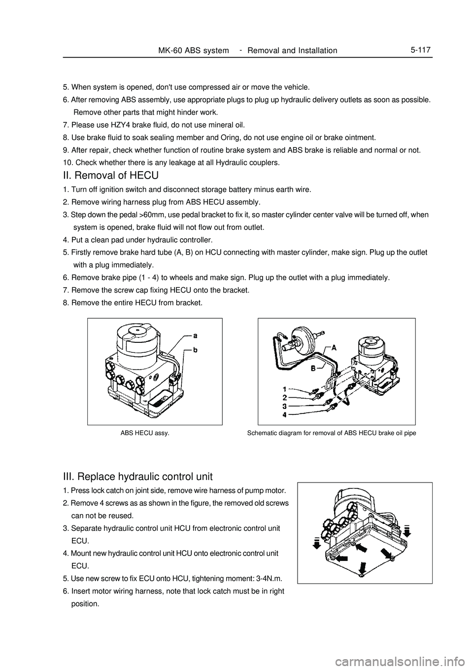
ABS HECU assy.III. Replace hydraulic control unit1. Press lock catch on joint side, remove wire harness of pump motor.
2. Remove 4 screws as as shown in the figure, the removed old screws
can not be reused.
3. Separate hydraulic control unit HCU from electronic control unit
ECU.
4. Mount new hydraulic control unit HCU onto electronic control unit
ECU.
5. Use new screw to fix ECU onto HCU, tightening moment: 3-4N.m.
6. Insert motor wiring harness, note that lock catch must be in right
position.MK-60 ABS system -
Removal and Installation5-117Schematic diagram for removal of ABS HECU brake oil pipe5. When system is opened, don't use compressed air or move the vehicle.
6. After removing ABS assembly, use appropriate plugs to plug up hydraulic delivery outlets as soon as possible.
Remove other parts that might hinder work.
7. Please use HZY4 brake fluid, do not use mineral oil.
8. Use brake fluid to soak sealing member and Oring, do not use engine oil or brake ointment.
9. After repair, check whether function of routine brake system and ABS brake is reliable and normal or not.
10. Check whether there is any leakage at all Hydraulic couplers.II. Removal of HECU1. Turn off ignition switch and disconnect storage battery minus earth wire.
2. Remove wiring harness plug from ABS HECU assembly.
3. Step down the pedal >60mm, use pedal bracket to fix it, so master cylinder center valve will be turned off, when
system is opened, brake fluid will not flow out from outlet.
4. Put a clean pad under hydraulic controller.
5. Firstly remove brake hard tube (A, B) on HCU connecting with master cylinder, make sign. Plug up the outlet
with a plug immediately.
6. Remove brake pipe (1 - 4) to wheels and make sign. Plug up the outlet with a plug immediately.
7. Remove the screw cap fixing HECU onto the bracket.
8. Remove the entire HECU from bracket.
Page 307 of 416

Fault symptom
Flameout, poor idle speedChapter 9 Engine EFI SystemI. Outline This system includes sensor that detects engine functioning. Engine ECU utilizes sensors installed at differ-
ent parts of engine to measure various working parameters of engine, accurately control oil injection quantity
according to control procedure set in engine electronic control unit, so engine could work in optimum mode
under various operating conditions, i. e. optimal power output, the most economical oil consumption, optimal
exhaust emissions. Engine ECU is capable of start up control, idle speed closed-loop control, air fuel ratio
closed-loop control, canister control, transient operation control, angle of ignition control, knocking control, air
conditioning control, coasting fuel cutoff and overspeed fuel cutoff control, ternary catalyst heating and protec-
tion control, system self-diagnosis etc.II. Inspection of control element1. Manifold intake pressure temperature sensor
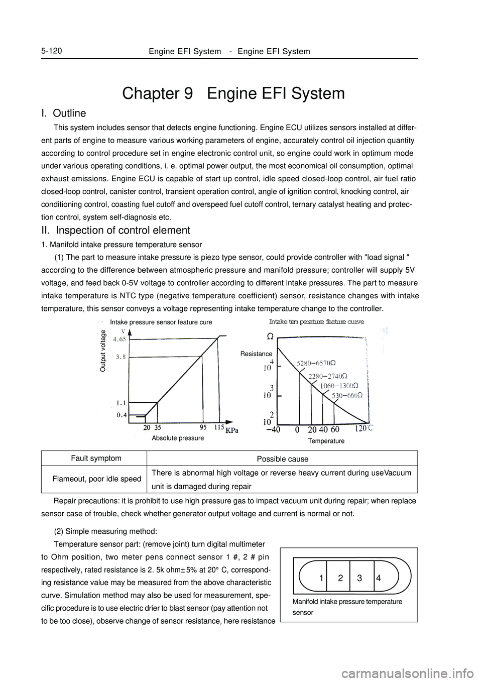
(1) The part to measure intake pressure is piezo type sensor, could provide controller with "load signal "
according to the difference between atmospheric pressure and manifold pressure; controller will supply 5V
voltage, and feed back 0-5V voltage to controller according to different intake pressures. The part to measure
intake temperature is NTC type (negative temperature coefficient) sensor, resistance changes with intake
temperature, this sensor conveys a voltage representing intake temperature change to the controller.
(2) Simple measuring method:
Temperature sensor part: (remove joint) turn digital multimeter
to Ohm position, two meter pens connect sensor 1 #, 2 # pinrespectively, rated resistance is 2. 5k ohm±5% at 20°C, correspond-ing resistance value may be measured from the above characteristic
curve. Simulation method may also be used for measurement, spe-
cific procedure is to use electric drier to blast sensor (pay attention not
to be too close), observe change of sensor resistance, here resistanceEngine EFI System-Engine EFI System5-120Possible cause
There is abnormal high voltage or reverse heavy current during useVacuum
unit is damaged during repair
Repair precautions: it is prohibit to use high pressure gas to impact vacuum unit during repair; when replace
sensor case of trouble, check whether generator output voltage and current is normal or not.1 2 3 4Manifold intake pressure temperature
sensor Intake pressure sensor feature cureIntake temperature feature curve
Output voltageAbsolute pressureTemperatureResistance
Page 310 of 416

Symptom Possible cause
Fail to start Man made faultSpeed sensor1 2 3Fault symptom Common cause
Dischrge overproof, increased oil consumption Man made fault5-1234#(black) pin respectively, now voltage should fluctuate quickly between 0. 1-0. 9V.
6. Speed sensor
(1) Use with oscillator. Oscillator is a fluted disc, originally has 60 teeth, but two teeth are absent. Oscillator
is mounted on crankshaft, and rotates with the crankshaft. When tooth tip passes by sensor end closely, the
oscillator which is made of ferromagnetic material cuts magnetic line of permanent magnet in the sensor, and
generates induced voltage in coil, which is output as rotating speed signal. Mounting torque: 8 ± 2 N.m
Repair precautions: use pressing in instead of hammering method for installation during repair.
(2) Simple measuring method:
(Remove joint) turn digital multimeter to ohm position, connect
two meter pens with sensor 2#, 3# pins respectively, rated resistance
at 20°C is 770-950 ohm.
(Connect joint) turn digital multimeter to AC voltage position,
connect two meter pens with sensor 2 #, 3# pins respectively, start up
engine, now voltage output should be available.
Suggestion: use oscillograph for vehicle use to check.
7. Phase sensor
(1) This sensor consists of a hall sensor and a rotor made of steel plate. Fix hall sensor, mount rotor on camshaft.
Rotor is a 180( range cylindrical face steel blade. When the blade covers hall sensor, high Level signal is output;
otherwise low level signal is output. This differentiates two different upper dead points. Repair precautions: avoid removing end cover as far as possible during repair, so as to avoid ingress of foreign
matter, which might result in abnormal damage of magnetic gate.
(2) Simple measuring method:
(Connect joint) turn on ignition switch but not start up engine, turn digital multimeter to DC voltage position,
connect two meter pens with sensor red, black conductors respectively, ensure reference voltage of 5V is available.
Start up engine, voltage output between green and black conductors should be available.
Suggestion: use oscillograph for vehicle use to check.
8. Idle speed regulator
(1) Idle speed regulator consists of a step motor and a sealing plug on its shaft, sealing plug may generate radial
displacement driven by step motor shaft, position of sealing plug determines extent of opening of by-pass airway,
so as to adjust the size of by-pass air quantity. Position of sealing plug is controlled by ECU output.Fault symptom
Too high idle speed, flameout at idle speedPossible cause
Since interior contamination is severe, regulating element
is blocked and leads to malfunction.
Repair precautions: dust and sand grain will result in damage of idle speed regulator. Intake air should be
filtered by dry air cleaner before entering idle speed regulator, filtration efficiency should exceed 99 %. ToEngine EFI System-Engine EFI System
Page 312 of 416

Symptom
Poor idle speed, malfunction etc
Symptom
Fail to start5-125 Repair precautions:
1. according to engine requirement, electric fuel pumps with different flows are available, they have the same
appearance, mountable fuel pump may not be exactly suitable, during repair, part number of fuel pump used must
be consistent with original one, wrong replacement is not permitted;
2. in order to prevent fuel pump from damaging, please do not run it in dry state for a long time;
3. in case fuel pump needs to be replaced, please pay attention to clean fuel tank and pipeline and replace fuel
filter.
(2) Simple measuring method:
(Remove joint) turn digital multimeter to ohm position, connect two meter pens with fuel pump pins
respectively, measure internal resistance, it should not be zero or infinite (namely not in short circuit, open circuit
condition).
(Connect joint) connect fuel pressure gauge on sucker, start up engine, run the engine at idle speed, now fuel
pressure of engine should be about 260kPa; unplug fuel pressure regulator vacuum tube, now fuel pressure should
be about 300KPa.
11. Canister control valve
(1) Canister in fuel evaporation control system adsorbs oil vapor from oil tank until saturated. Electronic
control unit controls opening of canister control valve, fresh air and saturated fuel vapor in canister form
regeneration stream, which is led into engine intake pipe again. Electronic control unit changes duty ratio of pulsing
signal to canister control valve solenoid according to different operating conditions of engine, thus controls flow
of regeneration stream. In addition, this flow is also influenced by pressure difference at both ends.
Possible cause
Entering of foreign matter into valve inside results in
corrosion or poor leak tightness etc
Repair precautions:
1. To install, airflow direction must meet the specification;
2. when black granules inside valve body result in malfunction of control valve, and control valve needs to be
replaced, please check the condition of canister;
3. avoid water, oil etc liquids from entering valve as far as possible during repair;
4. in order to avoid transfer of solid-borne noise, it is recommended to install canister control valve suspending
on the hose or use soft rubber to fix.
(2) Simple measuring method:
(Remove joint) turn digital multimeter to ohm position, connect two meter pens with canister control valve pins
respectively, rated resistance at 20°C is 22 - 30 ohm.
12. Ignition coil
(1) When earthing channel of primary winding is connected, this primary winding is charged. Once ECU cut
off primary winding circuit, charging stops, high voltage is induced in secondary winding at the same time, so spark
plug discharges. Ignition coil ZSK 22 (both ends of 2 secondary windings are connected with a spark plug
respectively, so these two spark plugs ignite simultaneously.
Possible cause
Too heavy current leads to burnout, damaged by external force Repair precautions: it is prohibited to use "short circuit ignition testing method" to test ignition function, soEngine EFI System-
Engine EFI System
Page 313 of 416

Engine ECU5-126as to avoid damaging electronic control unit.
(1) Simple measuring method:
(Remove joint) turn digital multimeter to ohm position, connect two meter pens with primary winding pinsrespectively, rated resistance at 2 0°C is 0. 4-0. 6 ohm for 2X2 type; on secondary winding, 11-15k ohm for 2x2 type.13. Electronic control unit ECU
Possible cause
Electric overload of externally connected
device leads to burnout of components inside
ECU and results in malfunction Symptom
Unsteady idle speed, poor speedup, failure to start, too high
idle, tail gas overproof, difficult to start, malfunction of air
conditioner, malfunction of fuel injector control, flameout
Repair precautions:
1. Don't remove ECU at discretion during repair;
2. ECU may be removed more than 1 minute after removing storage battery head;
3. Store removed ECU properly;
4. It is prohibited to attach any circuit onto connecting wire of ECU.
Simple measuring method:
1. (Connect joint) use engine data K-line to read engine trouble record;
2. (Remove joint) check whether ECU connecting wire is in good condition or not, mainly check whether ECU
power supply grounded circuit is normal or not;
3. Check whether external sensor works normally, whether output signal is credible, whether circuit is in good
condition;
4. Check whether actuator works normally, whether its circuit is in good condition;
5. Finally replace ECU to conduct test.
Judgment principle: "two interchange principle" ---interchange ECU, interchange fault symptom.III. Diagnostic system Description:
When engine ECU detects a trouble, engine trouble warning lamp on instrument will illuminate. In addition,
relevant diagnostic code will be recorded in ECU memory. Connect handheld tester with diagnostic interface on
automobile, read various data from automobile ECU. Connect handheld tester with diagnostic interface. Technical
personnel may also read fault code via blinking of instrument fault warning lamp.Engine EFI System-
Engine EFI System
Page 314 of 416

Flashing way of malfuntion code 17 for O2 sensor (3) Each fault code will blink for three times, interval time is 3s, after blinking for the third times, after an
interval of 3s, next fault code will blink. After blinking of all fault codes is finished, they will blink from begining
again. The following diagram shows engine fault warning lamp blinking mode for oxygen sensor fault code 17.5-127Terminal No. Terminal definition
4 Power supply (-)
7 Bus (signal)
16 Power supply (+)Diagnosis connector Notes: use tester cable to connect handheld tester with diagnostic interface, turn ignition switch to ON position,
operate tester, if tester displays that communication is not possible, the vehicle or tester fails.
Inspection diagnosis
1. Check engine fault warning lamp
(1) When ignition switch is turned to ON position and engine does not run, engine warning lamp on
instrument should illuminate.
(2) When engine runs, engine fault warning lamp should go out. If it still illuminates, diagnostic system
detects system fault or abnormity.
2. Use handheld tester to check diagnostic code
(1) Connect handheld tester according to corresponding pin.
(2) Turn ignition switch to ON position, turn on main switch of handheld tester.
(3) Use handheld tester to detect and check diagnostic code, refer to fault diagnostic code table. (For
operation of handheld tester, see instruction manual of handheld tester)
3. Engine fault warning lamp displays fault code through blinking code, so professional may make fault
judgment in case of emergency.
(1)Turn ignition switch to ON position.
(2) Short signal pin (9#) and negative pole (4#) for more than 2. 5s,then disconnect them,detection fault lamp
on dashboard will blink the faults in fault code according to their occurrence sequence.See from terminal outlet
endConnect in jump way over 2.5s and
disconnect
Diagnosis connectorDiagnosis connectorEngine EFI System-
Engine EFI System