check engine GEELY MK 2008 Owner's Manual
[x] Cancel search | Manufacturer: GEELY, Model Year: 2008, Model line: MK, Model: GEELY MK 2008Pages: 416, PDF Size: 25.19 MB
Page 59 of 416
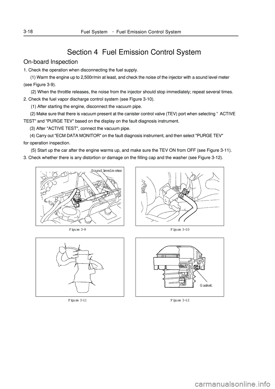
Section 4 Fuel Emission Control SystemOn-board Inspection1. Check the operation when disconnecting the fuel supply.
(1) Warm the engine up to 2,500r/min at least, and check the noise of the injector with a sound level meter
(see Figure 3-9).
(2) When the throttle releases, the noise from the injector should stop immediately; repeat several times.
2. Check the fuel vapor discharge control system (see Figure 3-10).
(1) After starting the engine, disconnect the vacuum pipe.
(2) Make sure that there is vacuum present at the canister control valve (TEV) port when selecting ”ACTIVE
TEST" and "PURGE TEV" based on the display on the fault diagnosis instrument.
(3) After "ACTIVE TEST", connect the vacuum pipe.
(4) Carry out "ECM DATA MONITOR" on the fault diagnosis instrument, and then select "PURGE TEV"
for operation inspection.
(5) Start up the car after the engine warms up, and make sure the TEV ON from OFF (see Figure 3-11).
3. Check whether there is any distortion or damage on the filling cap and the washer (see Figure 3-12).Figure 3-9 Figure 3-10Fuel SystemFuel Emission Control System3-18Figure 3-11 Figure 3-12Sound level meter
Gasket -
Page 63 of 416
2. Check the engine coolant quantity in the compensating tank.
The coolant level should be between LOW and FULL.
3. Check the coolant quality.
(1) Remove the radiator cover.
Do not remove the radiator cover when the engine and the radiator are still hot in order to avoid scalding
since the liquid vapor may inject.
(2) Check whether there are excessive deposit and rust or sundries around the radiator cover. The coolant is
not allowed to contact with oil.
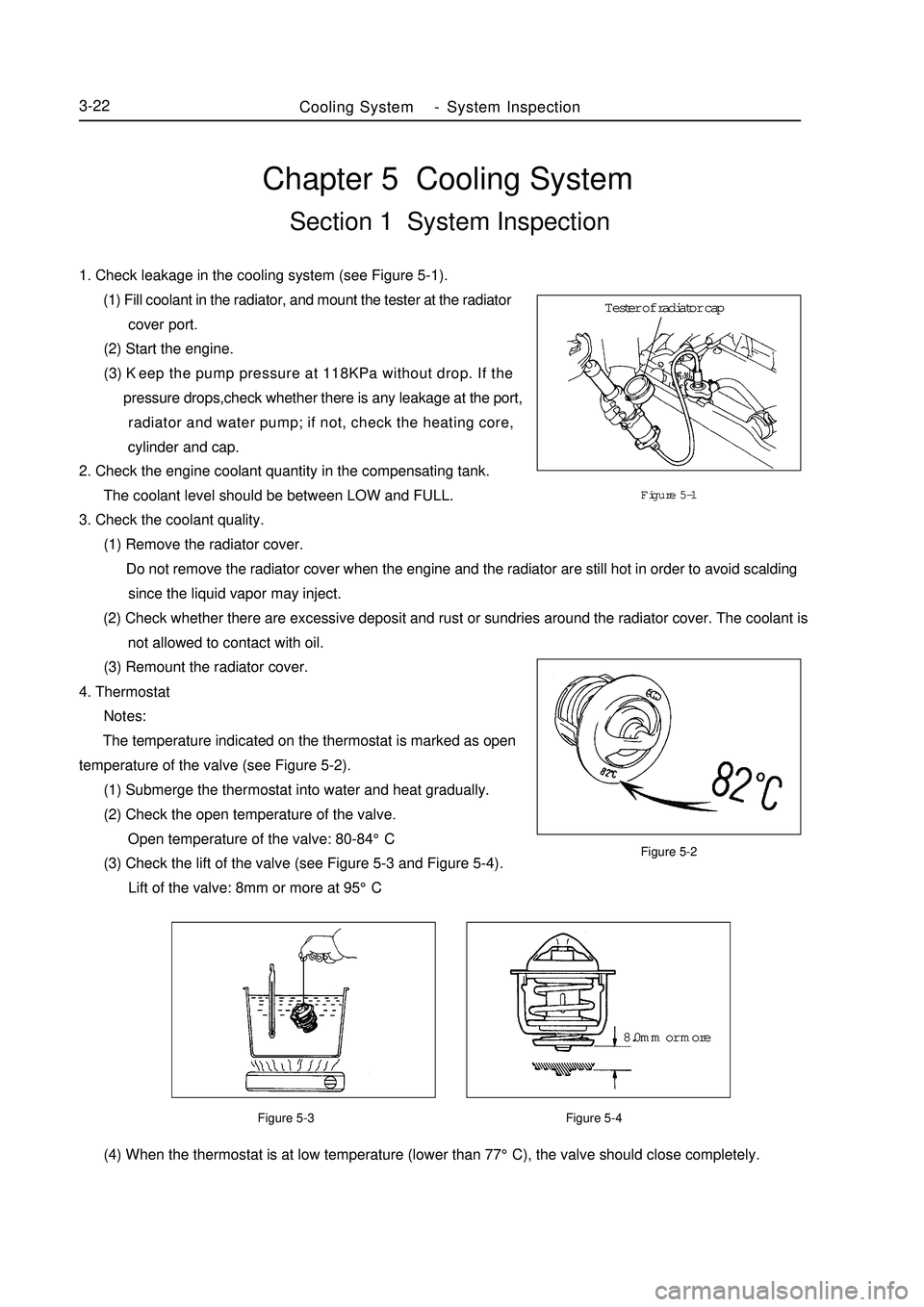
(3) Remount the radiator cover.Chapter 5 Cooling SystemSection 1 System Inspection1. Check leakage in the cooling system (see Figure 5-1).
(1) Fill coolant in the radiator, and mount the tester at the radiator
cover port.
(2) Start the engine.
(3) Keep the pump pressure at 118KPa without drop. If the
pressure drops,check whether there is any leakage at the port,
radiator and water pump; if not, check the heating core,
cylinder and cap.Figure 5-1
Figure 5-2
Figure 5-3 Figure 5-4 (4) When the thermostat is at low temperature (lower than 77°C), the valve should close completely.Cooling SystemSystem Inspection3-224. Thermostat
Notes:
The temperature indicated on the thermostat is marked as open
temperature of the valve (see Figure 5-2).
(1) Submerge the thermostat into water and heat gradually.
(2) Check the open temperature of the valve.
Open temperature of the valve: 80-84°C
(3) Check the lift of the valve (see Figure 5-3 and Figure 5-4).
Lift of the valve: 8mm or more at 95°CTester of radiator cap
8.0mm or more -
Page 64 of 416

Figure 5-6
Figure 5-7Above 93°CFigure 5-5Cooling SystemSystem Inspection3-235. Fan
(1) At low temperature (lower than 83°C), check the operation of
the cooling fan.
a. The ignition switch is set to ON.
b. The cooling fan should stop.
c. Disconnect the connector of the water temperature sensor.
(see Figure 5-5)
d.Touch the ground with a wire.
e.Check if the cooling fan rotates.
f. Re-connect the connector of the water temperature sensor.
(2) At high temperature (more than 93°C), check the operation of
the fan (see Figure 5-6).
a. Start the engine, and enable the coolant temperature higher
than 93°C.
b.Check whether the cooling fan rotates.
If not, replace the water temperature switch.
(3) Check the cooling fan (see Figure 5-7).
a. Disconnect the joint of the cooling fan.
b. Connect the battery and the ammeter with the connector.
c. The cooling fan should rotate stably and check the current
readings.
Standard current: 5.7-7.7A.
d. Connect the connector of the cooling fan.disconnectBattery Amper meter -
Page 71 of 416
The valve body fails.
12. The vehicle shifts before or after some gear points in the running status.
The vehicle switch or parking switch fails.
13. The vehicle has poor acceleration in running.
(1)The clutch or brake fails.
(2)The engine system fails.
14. The vehicle vibrates when it runs at a constant speed or accelerating speed.
(1)The hydraulic torque clutch pressure or hydraulic torque meter fails.
(2)The engine system or valve fails.
15. The acceleration switch system fails.
(1)The acceleration switch or ignition switch fails.
(2)The connector or automatic transmission control unit fails.I. Automatic transmissions Removal1. Put the select lever in "N" position
2. Remove 3 bolts of the flexibility plate (engine side)
3. Remove starter and 2 cooling hoses.
4. Disconnect neutral switch connector and odometer sensor.
5. Loosen the drain screw under the housing to bleed ATF and tighten the drain screw with sealing glue when
assembling. Tightening torque is 29~35N.m
6. Loosen the locking bolt for select lever cable.
7. Remove Drive Shaft LH&RH, using plastic stopper in the oil sealing of differential.
8. Detach suspension bolts.
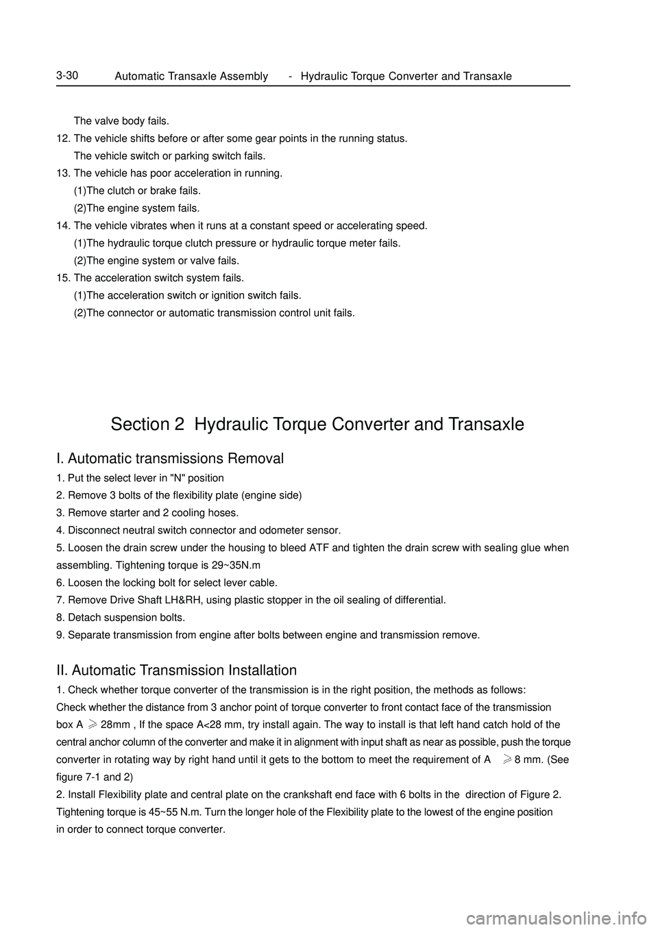
9. Separate transmission from engine after bolts between engine and transmission remove.II. Automatic Transmission Installation1. Check whether torque converter of the transmission is in the right position, the methods as follows:
Check whether the distance from 3 anchor point of torque converter to front contact face of the transmission
box A 28mm , If the space A<28 mm, try install again. The way to install is that left hand catch hold of the
central anchor column of the converter and make it in alignment with input shaft as near as possible, push the torque
converter in rotating way by right hand until it gets to the bottom to meet the requirement of A 28 mm. (See
figure 7-1 and 2)
2. Install Flexibility plate and central plate on the crankshaft end face with 6 bolts in the direction of Figure 2.
Tightening torque is 45~55 N.m. Turn the longer hole of the Flexibility plate to the lowest of the engine position
in order to connect torque converter.Section 2 Hydraulic Torque Converter and TransaxleAutomatic Transaxle Assembly Hydraulic Torque Converter and Transaxle3-30 -
Page 73 of 416
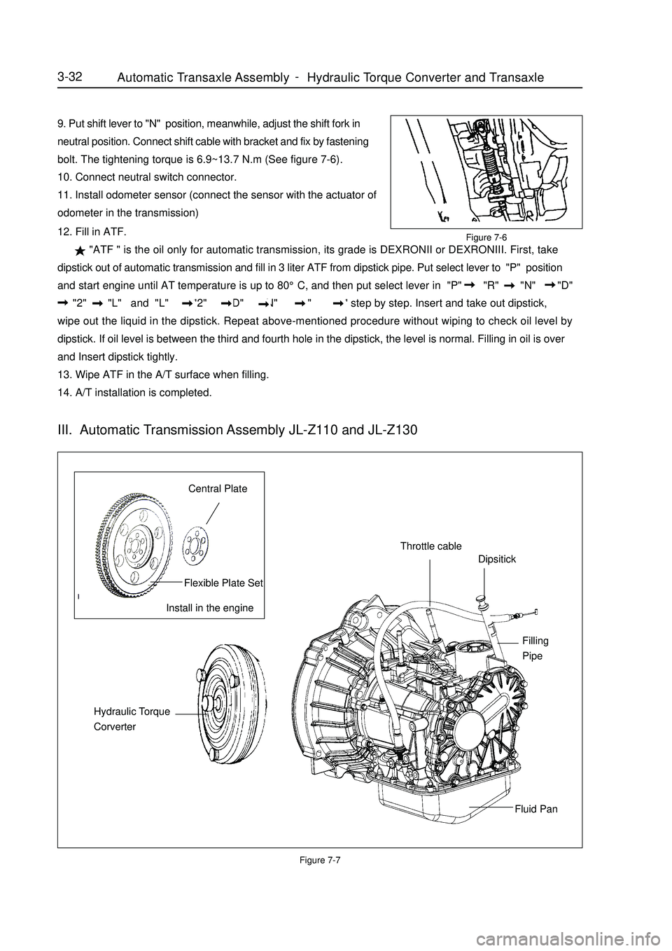
9. Put shift lever to "N" position, meanwhile, adjust the shift fork in
neutral position. Connect shift cable with bracket and fix by fastening
bolt. The tightening torque is 6.9~13.7 N.m (See figure 7-6).
10. Connect neutral switch connector.
11. Install odometer sensor (connect the sensor with the actuator of
odometer in the transmission)Figure 7-712. Fill in ATF.
"ATF " is the oil only for automatic transmission, its grade is DEXRONII or DEXRONIII. First, take
dipstick out of automatic transmission and fill in 3 liter ATF from dipstick pipe. Put select lever to "P" position
and start engine until AT temperature is up to 80°C, and then put select lever in "P" "R" "N" "D"
"2" "L" and "L" "2" "D" "N" "R" "P" step by step. Insert and take out dipstick,
wipe out the liquid in the dipstick. Repeat above-mentioned procedure without wiping to check oil level by
dipstick. If oil level is between the third and fourth hole in the dipstick, the level is normal. Filling in oil is over
and Insert dipstick tightly.
13. Wipe ATF in the A/T surface when filling.
14. A/T installation is completed.3-32Install in the engineCentral PlateFlexible Plate SetThrottle cableDipsitickFilling
PipeFluid Pan Hydraulic Torque
CorverterIII. Automatic Transmission Assembly JL-Z110 and JL-Z130Figure 7-6Automatic Transaxle Assembly Hydraulic Torque Converter and Transaxle -
Page 77 of 416
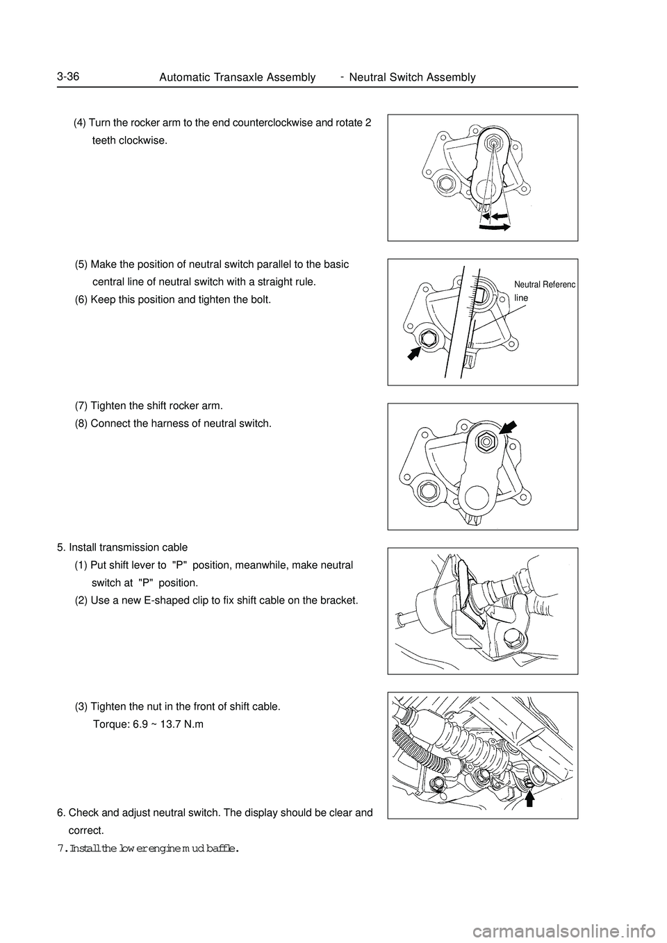
Automatic Transaxle Assembly Neutral Switch Assembly3-36 (4) Turn the rocker arm to the end counterclockwise and rotate 2
teeth clockwise.
(5) Make the position of neutral switch parallel to the basic
central line of neutral switch with a straight rule.
(6) Keep this position and tighten the bolt.
(7) Tighten the shift rocker arm.
(8) Connect the harness of neutral switch.
5. Install transmission cable
(1) Put shift lever to "P" position, meanwhile, make neutral
switch at "P" position.
(2) Use a new E-shaped clip to fix shift cable on the bracket.
(3) Tighten the nut in the front of shift cable.
Torque: 6.9 ~ 13.7 N.m
6. Check and adjust neutral switch. The display should be clear and
correct.
7. Install the lower engine mud baffle.Neutral Referencline -
Page 78 of 416

Part IV ChassisChapter 1 Transmission ControlSection 1 Introduction of Transmission ControlI. Description on Transmission ControlThis model is equipped with cable Transmission Controls, respectively used for 1.3L, 1.5L and 1.6L engine. Their
gears are: 5 forward gears + 1 reverse gear.II. Symptom TableUse the table below to help you find the cause of the problem. The numbers indicate the priority of the likely cause
of the problem. Check each part in order. If necessary, replace these parts.
Suspected Area
1. Transmission Control selector (position changing) cable
(improperly assembled)
2. Cable or shift lever (worn)
3. Cable assembly (incorrect)
4. Transmission (faulty)
1. Transmission control selector (position changing ) cable
(improperly assembled)
2. Cable or shift lever (worn)
3. Cable assembly (incorrect)
4. Transmission (faulty) Symptom
Transmission out of gear
Transmission shift difficultChassisTransmission Control4-1 -
Page 87 of 416
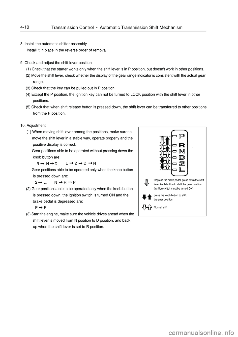
4-108. Install the automatic shifter assembly
Install it in place in the reverse order of removal.
9. Check and adjust the shift lever position
(1) Check that the starter works only when the shift lever is in P position, but doesn't work in other positions.
(2) Move the shift lever, check whether the display of the gear range indicator is consistent with the actual gear
range.
(3) Check that the key can be pulled out in P position.
(4) Except the P position, the ignition key can not be turned to LOCK position with the shift lever in other
positions.
(5) Check that when shift release button is pressed down, the shift lever can be transferred to other positions
from the P position.
10. Adjustment
(1) When moving shift lever among the positions, make sure to
move the shift lever in a stable way, operate properly and the
positive display is correct.
Gear positions able to be operated without pressing down the
knob button are:
R N D,L 2 D N
Gear positions able to be operated only when the knob button
is pressed down are:
2 L,N R P
(2) Gear positions able to be operated only when the knob button
is pressed down, the ignition switch is turned ON and the
brake pedal is depressed are:
P R
(3) Start the engine, make sure the vehicle drives ahead when the
shift lever is moved from N position to D position, and back
up when the shift lever is set to R position.Depress the brake pedal, press down the shift
lever knob button to shift the gear position.
(ignition switch must be turned ON)
press the knob button to shift
the gear position
Normal shiftTransmission ControlAutomatic Transmission Shift Mechanism -
Page 88 of 416

Chapter 2 Accelerator Pedal DeviceSection 1 Introduction of Accelerator PedalComponent View
Replacement1. Disconnect the accelerator cables.
Loosen the accelerator cables and the bolts on the accelerator cable frame of the engine, and then disconnect
the accelerator cables from the rocker of the motor restrictor.
2. Remove the accelerator pedal.
(1)Remove the two bolts that connect the accelerator pedal and the body.
(2)Disconnect the accelerator cables.
3. Remove the accelerator cables.Accderator
Pedal Rotation
AssemloyAccelerator pedal
bracket assemblyLubrication
bushingSpeaial
Spring ClipAccelerator cable assemblyHex. flange nut22~29N .mAccelerator cableAccelerator Pedal DeviceIntroduction of Accelerator Pedal4-114. Install the accelerator cables and accelerator pedal assembly in a reverse order.
Note:
(1)The torque of the bolt is 20~25N.m.
(2)Adjust the position of the accelerator cables properly to obtain a proper tension.
(3)Check that the acceleration runs freely and reliably. -
Page 89 of 416

Chapter 3 Clutch Control SystemSection 1 Introduction of Clutch CentrolI. Description A hydraulic clutch control system is equipped which can be used in cars with various displacements (including
1.3L, 1.5L and1.6L).II. Symptom Table The table below lists the common symptoms and possible causes of the failures. The number means the
possible sequence of the causes. Check the parts, and replace the corresponding parts if necessary.
Suspected area
1. Engine fixture is loosened.
2. Clutch disc shakes seriously.
3. Clutch disc is contaminated by oil or wore down.
4. Torque spring of the clutch disc is damaged.
5. Clutch disc is hardened.
6. Diaphragm spring is not aligned on the top.
1. There is air in the clutch oil pipe.
2. Cup of the master cylinder is damaged.
3. Cup of the wheel cylinder is damaged.
1. Clutch release bearing is worn out, contaminated or damaged.
2. Torque spring of the clutch disc is damaged.
1. Clutch pedal has maladjusted free stroke.
2. Clutch disc is contaminated by oil.
3. Clutch disc is worn.
4. Diaphragm spring is damaged.
5. Platen is deformed.
6. Flywheel is deformed.
1. Clutch pedal has maladjusted free stroke.
2. There is air in the clutch oil pipe.
3. Cup of the master cylinder is damaged.
4. Cup of the wheel cylinder is damaged.
5. Clutch disc id deformed or wiggled.
6. Clutch disc is worn out.
7. Clutch disc is contaminated or burned out.
8. Clutch disc is contaminated by oil.
9. Clutch disc has no lube on its spline. Symptom
Clutch is trapped or shaken.
Clutch pedal is loosened.
Abnormal noise occurs.
Clutch skids.
Clutch can not be separated.Clutch Control SystemIntroduction of Clutch Centrol4-12 -