air conditioning GEELY MK 2008 Workshop Manual
[x] Cancel search | Manufacturer: GEELY, Model Year: 2008, Model line: MK, Model: GEELY MK 2008Pages: 416, PDF Size: 25.19 MB
Page 3 of 416
Geely “MK” series sedans (JL7132U,JL7132HU,JL7152U,JL7152HU,JL7162U) are brand
new superior models developed by Geely Group who has fully proprietary intellectual property
rights. As a result of the three years of involvements and efforts of the experts from Geely Automo-
bile Research Institute, these sedans reach international leading level in model design, power,
sense of comfort, safety and manufacturing technology while featured in beautiful appearance,
economy, environment protection and safety. The meaning of MK implied that Geely Automobile
has a great development from caterpillar to butterfly. With respect to the power, Geely “MK” series
sedans are equipped with 1.3L, 1.5L, and 1.6L EFI engines developed and manufactured by Geely
itself, and has reached “Chinese III” (Euro III) emission standard.
This manual contains a detailed description of the structures and principles, servicing and adjustment,
removal, assembling technology and matching clearance of the parts of the Geely “MK” sedans
with torque information of the bolts and nuts as well as schematic diagram for special tool operation.
This manual also introduces the transmission control system of the automatic transmission models,
vehicle electric circuits and elaborates ABS system, SRS, BOSCH M7.9.7 electronic control fuel
injection and ignition system, rear parking radar, sound, air conditioning and onboard hands-free
phone system. You can refer to this manual for the information about the regular maintenance,
servicing, adjustment, troubleshooting, removal and installation procedure, specific operations of
the “MK” sedans.
This manual covers the matching relation among the engine assembly, transmission assembly and
the vehicle, but does not have the further description of the structures and principles of the engine
and transmission assemblies and their servicing process. You can refer to the service manuals
solely prepared for engine assembly and transmission assembly for these information.
All information in this manual is based on the latest products released at the time of publication of
this manual. However, the specifications and procedures may need to be modified, and the subse-
quent change will be revealed in later versions.
This manual is prepared by Geely Automobile Research Institute under the assistance of technical
staff from Zhejiang Geely Automobile Co., Ltd and Geely International Corporation. Readers
discovering during the use of this manual the errors and careless omissions due to limited skills of
the preparers and tight schedule are encouraged and pled to contact Geely International in time for
our timely correction of the mistakes.ForewordGeely International Corporation
Nov . 2007
Page 8 of 416
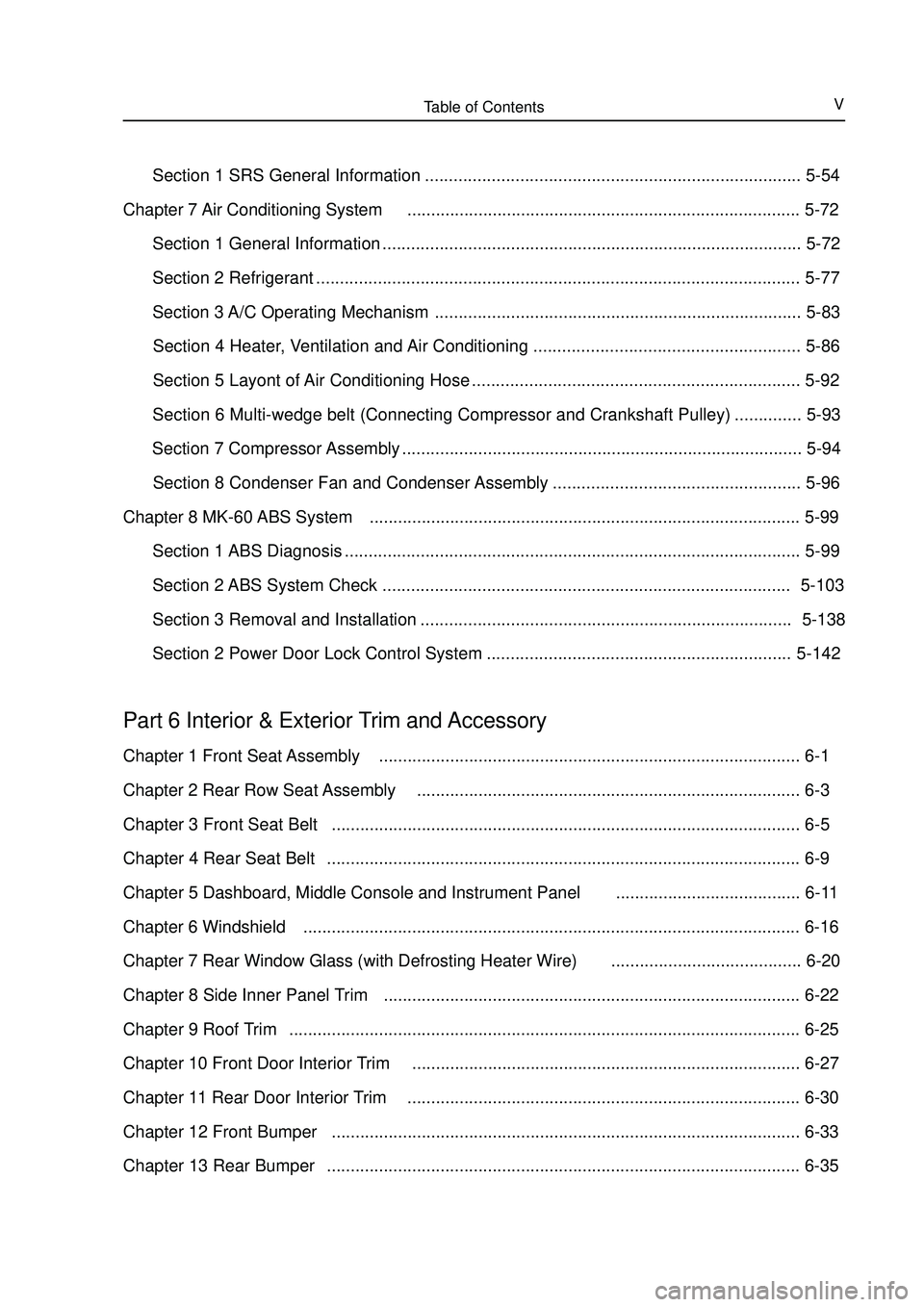
Table of ContentsV Section 1 SRS General Information ............................................................................... 5-54
Chapter 7 Air Conditioning System................................................................................... 5-72
Section 1 General Information ........................................................................................ 5-72
Section 2 Refrigerant ...................................................................................................... 5-77
Section 3 A/C Operating Mechanism ............................................................................. 5-83
Section 4 Heater, Ventilation and Air Conditioning ........................................................ 5-86
Section 5 Layont of Air Conditioning Hose ..................................................................... 5-92
Section 6 Multi-wedge belt (Connecting Compressor and Crankshaft Pulley) .............. 5-93
Section 7 Compressor Assembly .................................................................................... 5-94
Section 8 Condenser Fan and Condenser Assembly .................................................... 5-96
Chapter 8 MK-60 ABS System........................................................................................... 5-99
Section 1 ABS Diagnosis ................................................................................................ 5-99
Section 2 ABS System Check ...................................................................................... 5-103
Section 3 Removal and Installation .............................................................................. 5-138
Section 2 Power Door Lock Control System ................................................................5-142Part 6 Interior & Exterior Trim and AccessoryChapter 1 Front Seat Assembly......................................................................................... 6-1
Chapter 2 Rear Row Seat Assembly................................................................................. 6-3
Chapter 3 Front Seat Belt................................................................................................... 6-5
Chapter 4 Rear Seat Belt.................................................................................................... 6-9
Chapter 5 Dashboard, Middle Console and Instrument Panel....................................... 6-11
Chapter 6 Windshield......................................................................................................... 6-16
Chapter 7 Rear Window Glass (with Defrosting Heater Wire)........................................ 6-20
Chapter 8 Side Inner Panel Trim........................................................................................ 6-22
Chapter 9 Roof Trim............................................................................................................ 6-25
Chapter 10 Front Door Interior Trim.................................................................................. 6-27
Chapter 11 Rear Door Interior Trim................................................................................... 6-30
Chapter 12 Front Bumper................................................................................................... 6-33
Chapter 13 Rear Bumper.................................................................................................... 6-35
Page 30 of 416
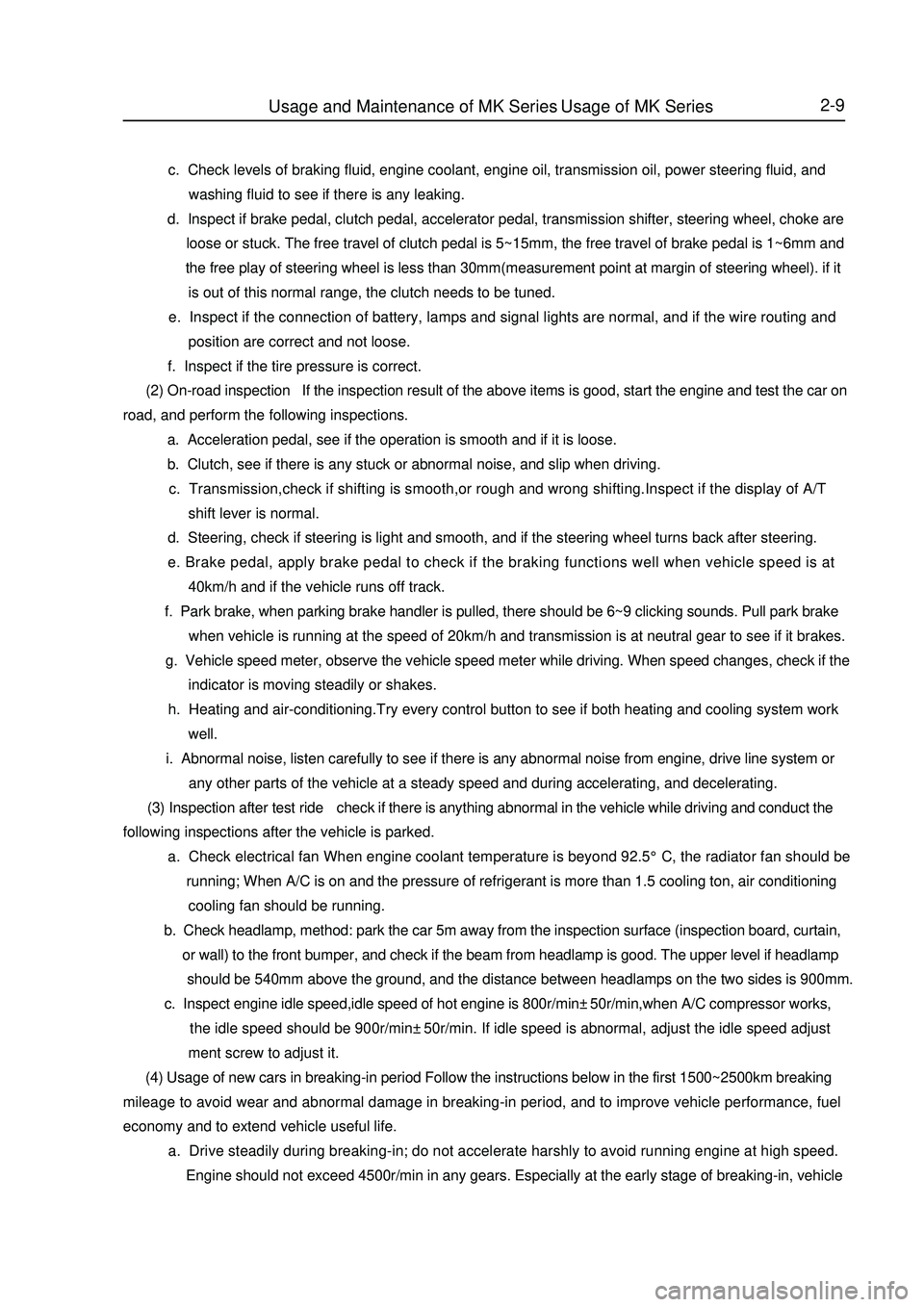
2-9 c. Check levels of braking fluid, engine coolant, engine oil, transmission oil, power steering fluid, and
washing fluid to see if there is any leaking.
d. Inspect if brake pedal, clutch pedal, accelerator pedal, transmission shifter, steering wheel, choke are
loose or stuck. The free travel of clutch pedal is 5~15mm, the free travel of brake pedal is 1~6mm and
the free play of steering wheel is less than 30mm(measurement point at margin of steering wheel). if it
is out of this normal range, the clutch needs to be tuned.
e. Inspect if the connection of battery, lamps and signal lights are normal, and if the wire routing and
position are correct and not loose.
f. Inspect if the tire pressure is correct.
(2) On-road inspection If the inspection result of the above items is good, start the engine and test the car on
road, and perform the following inspections.
a. Acceleration pedal, see if the operation is smooth and if it is loose.
b. Clutch, see if there is any stuck or abnormal noise, and slip when driving.
c. Transmission,check if shifting is smooth,or rough and wrong shifting.Inspect if the display of A/T
shift lever is normal.
d. Steering, check if steering is light and smooth, and if the steering wheel turns back after steering.
e. Brake pedal, apply brake pedal to check if the braking functions well when vehicle speed is at
40km/h and if the vehicle runs off track.
f. Park brake, when parking brake handler is pulled, there should be 6~9 clicking sounds. Pull park brake
when vehicle is running at the speed of 20km/h and transmission is at neutral gear to see if it brakes.
g. Vehicle speed meter, observe the vehicle speed meter while driving. When speed changes, check if the
indicator is moving steadily or shakes.
h. Heating and air-conditioning.Try every control button to see if both heating and cooling system work
well.
i. Abnormal noise, listen carefully to see if there is any abnormal noise from engine, drive line system or
any other parts of the vehicle at a steady speed and during accelerating, and decelerating.
(3) Inspection after test ride check if there is anything abnormal in the vehicle while driving and conduct the
following inspections after the vehicle is parked.
a. Check electrical fan When engine coolant temperature is beyond 92.5°C, the radiator fan should be
running; When A/C is on and the pressure of refrigerant is more than 1.5 cooling ton, air conditioning
cooling fan should be running.
b. Check headlamp, method: park the car 5m away from the inspection surface (inspection board, curtain,
or wall) to the front bumper, and check if the beam from headlamp is good. The upper level if headlamp
should be 540mm above the ground, and the distance between headlamps on the two sides is 900mm.
c. Inspect engine idle speed,idle speed of hot engine is 800r/min±50r/min,when A/C compressor works,
the idle speed should be 900r/min±50r/min. If idle speed is abnormal, adjust the idle speed adjust
ment screw to adjust it.
(4) Usage of new cars in breaking-in period Follow the instructions below in the first 1500~2500km breaking
mileage to avoid wear and abnormal damage in breaking-in period, and to improve vehicle performance, fuel
economy and to extend vehicle useful life.
a. Drive steadily during breaking-in; do not accelerate harshly to avoid running engine at high speed.
Engine should not exceed 4500r/min in any gears. Especially at the early stage of breaking-in, vehicleUsage and Maintenance of MK Series - Usage of MK Series
Page 259 of 416
Item
Temperature regulation method
CompressorNominal refrigerating capacity / w
Displacement / (ml /r)
Model
Power consumed by magnetic clutch /W
Lubricating oil / ml
BlowerMaximum air quantity / (m3/h)
Air regulation
Motor power / W
Dimension /mm
Heat exchange quantity / W
Fan motor current / A
Fan motor revolution / (r/min)
Dimension /mm
Refrigerating capacity /W
Thermostatic expansion valve Condenser
Evaporator
Driving belt
Refrigerant filling amount/gChapter 7 Air Conditioning SystemSection 1 General InformationOverview:Air-conditioning system consists of refrigeration and heating parts. Refrigerating system mainly consists of
compressor, condenser and evaporator etc, it adsorbs heat in the air through circulation of refrigerant, so as to
reduce air temperature in car body and eliminate water vapour in air, to achieve the purpose of temperature drop
and dehumidification. Heating system mainly consists of heat exchanger and heater unit. It utilizes heat of engine
cooling water to heat air via heat exchanger, so as to achieve the purpose of heating. Regulation and control of
temperature, humidity and flow rate of air in car body is realized via heating and refrigeration systems separately
or jointly.
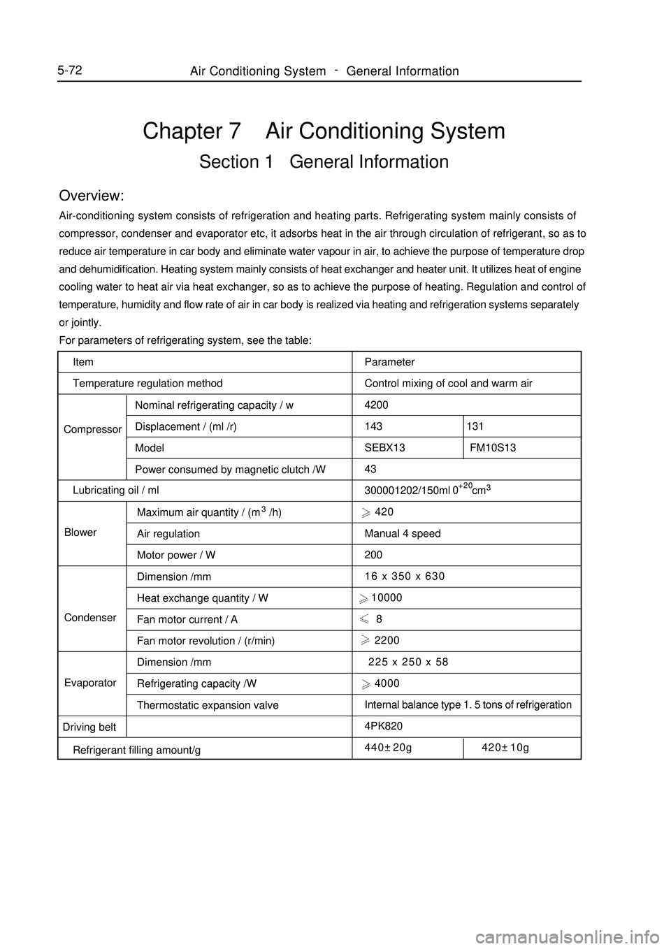
For parameters of refrigerating system, see the table:
Parameter
Control mixing of cool and warm air
4200
143 131
SEBX13 FM10S13
43
300001202/150ml cm3 420
Manual 4 speed
200
16 x 350 x 630
10000
8
2200
225 x 250 x 58
4000
Internal balance type 1. 5 tons of refrigeration
4PK820
440±20g 420±10g+20
05-72Air Conditioning System -
General Information
Page 260 of 416
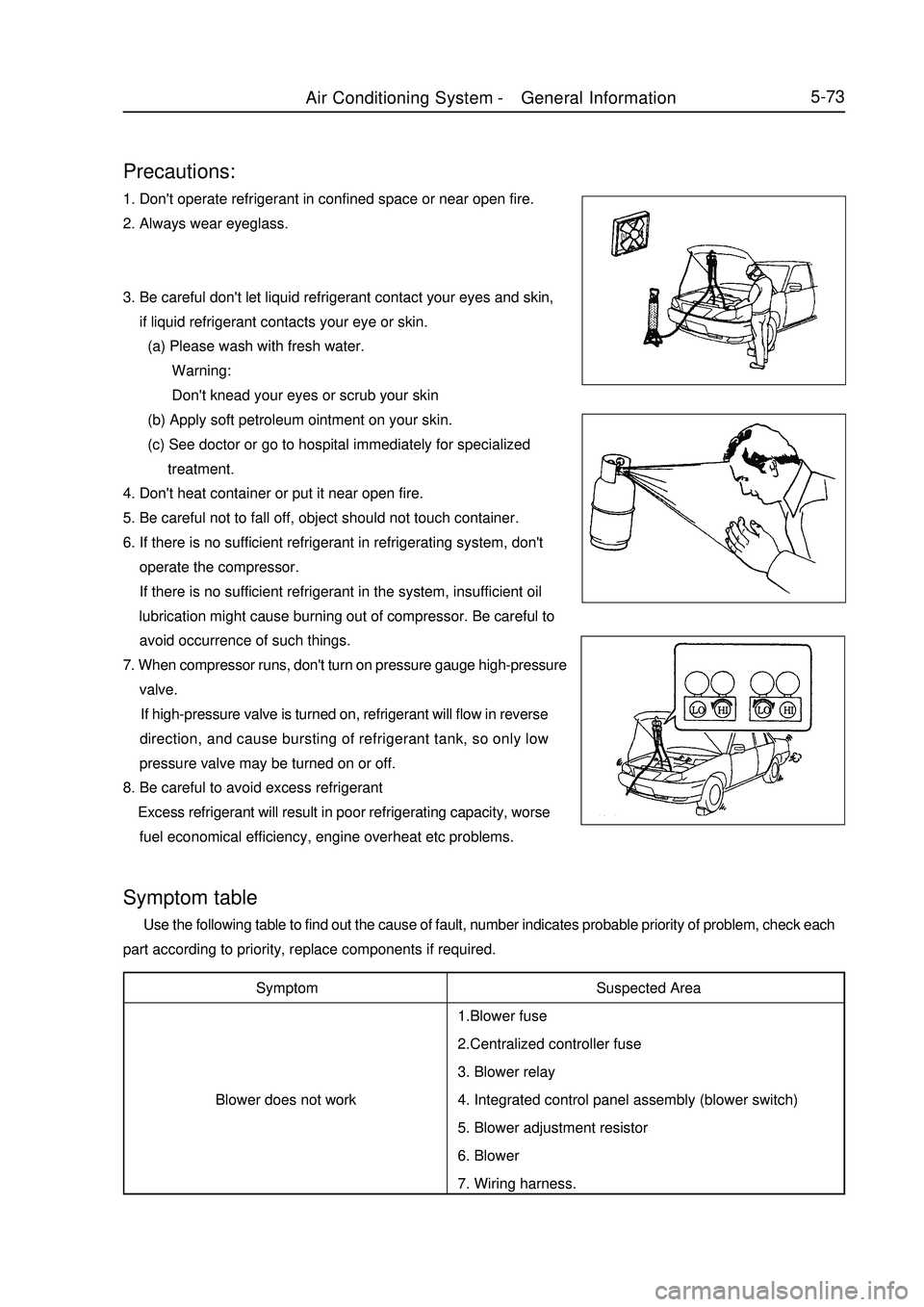
5-73Precautions:1. Don't operate refrigerant in confined space or near open fire.
2. Always wear eyeglass.
3. Be careful don't let liquid refrigerant contact your eyes and skin,
if liquid refrigerant contacts your eye or skin.
(a) Please wash with fresh water.
Warning:
Don't knead your eyes or scrub your skin
(b) Apply soft petroleum ointment on your skin.
(c) See doctor or go to hospital immediately for specialized
treatment.
4. Don't heat container or put it near open fire.
5. Be careful not to fall off, object should not touch container.
6. If there is no sufficient refrigerant in refrigerating system, don't
operate the compressor.
If there is no sufficient refrigerant in the system, insufficient oil
lubrication might cause burning out of compressor. Be careful to
avoid occurrence of such things.
7. When compressor runs, don't turn on pressure gauge high-pressure
valve.
If high-pressure valve is turned on, refrigerant will flow in reverse
direction, and cause bursting of refrigerant tank, so only low
pressure valve may be turned on or off.
8. Be careful to avoid excess refrigerant
Excess refrigerant will result in poor refrigerating capacity, worse
fuel economical efficiency, engine overheat etc problems.Symptom
Blower does not workSymptom table Use the following table to find out the cause of fault, number indicates probable priority of problem, check each
part according to priority, replace components if required.
Suspected Area
1.Blower fuse
2.Centralized controller fuse
3. Blower relay
4. Integrated control panel assembly (blower switch)
5. Blower adjustment resistor
6. Blower
7. Wiring harness.Air Conditioning System -General Information
Page 261 of 416
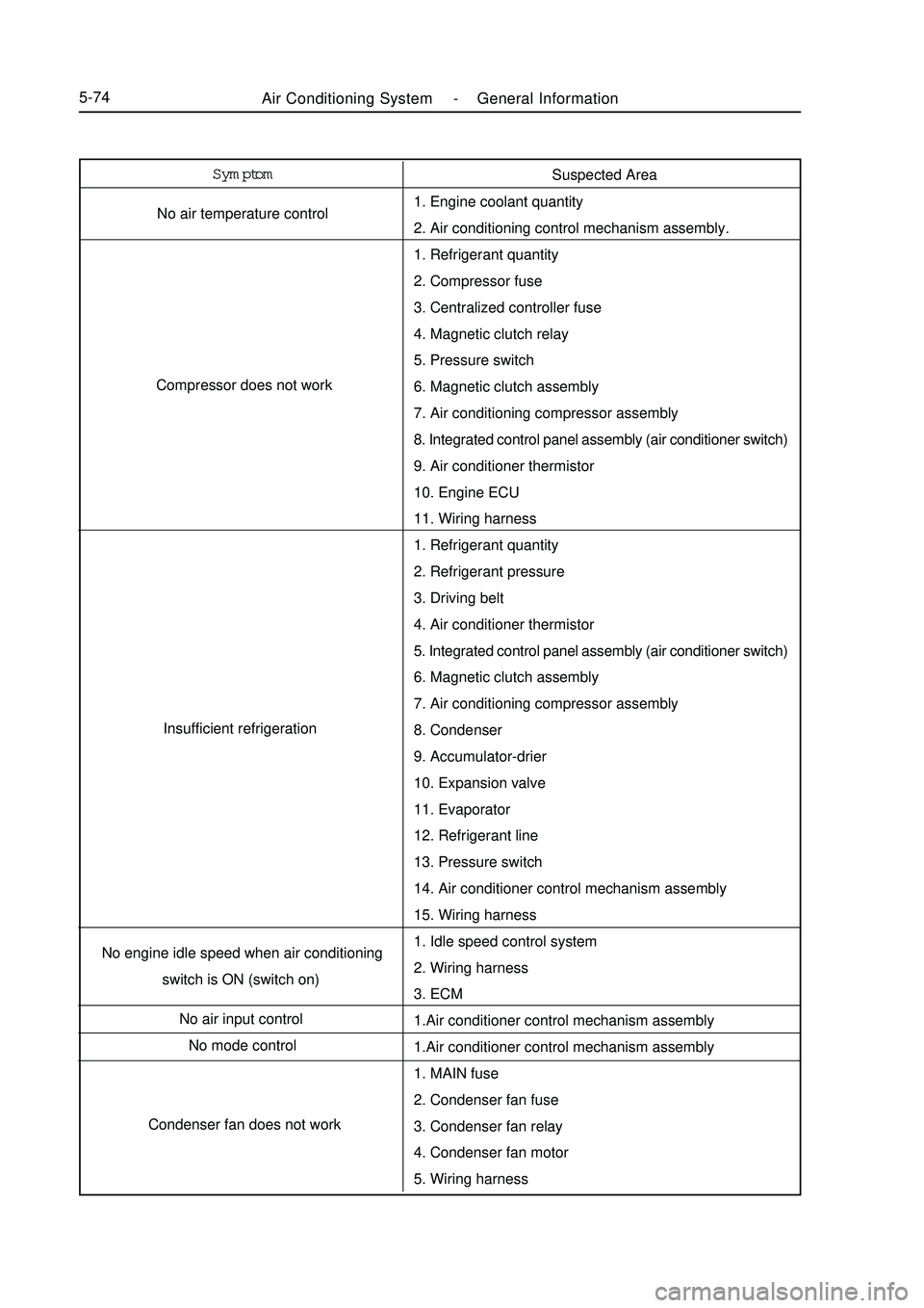
Air Conditioning System -General Information5-74Symptom
No air temperature control
Compressor does not work
Insufficient refrigeration
No engine idle speed when air conditioning
switch is ON (switch on)
No air input control
No mode control
Condenser fan does not workSuspected Area
1. Engine coolant quantity
2. Air conditioning control mechanism assembly.
1. Refrigerant quantity
2. Compressor fuse
3. Centralized controller fuse
4. Magnetic clutch relay
5. Pressure switch
6. Magnetic clutch assembly
7. Air conditioning compressor assembly
8. Integrated control panel assembly (air conditioner switch)
9. Air conditioner thermistor
10. Engine ECU
11. Wiring harness
1. Refrigerant quantity
2. Refrigerant pressure
3. Driving belt
4. Air conditioner thermistor
5. Integrated control panel assembly (air conditioner switch)
6. Magnetic clutch assembly
7. Air conditioning compressor assembly
8. Condenser
9. Accumulator-drier
10. Expansion valve
11. Evaporator
12. Refrigerant line
13. Pressure switch
14. Air conditioner control mechanism assembly
15. Wiring harness
1. Idle speed control system
2. Wiring harness
3. ECM
1.Air conditioner control mechanism assembly
1.Air conditioner control mechanism assembly
1. MAIN fuse
2. Condenser fan fuse
3. Condenser fan relay
4. Condenser fan motor
5. Wiring harness
Page 262 of 416
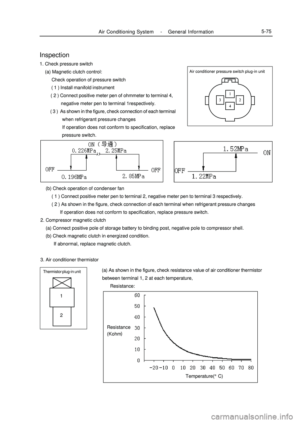
Air Conditioning System -General Information5-75Air conditioner pressure switch plug-in unitInspection1. Check pressure switch
(a) Magnetic clutch control:
Check operation of pressure switch
( 1 ) Install manifold instrument
( 2 ) Connect positive meter pen of ohmmeter to terminal 4,
negative meter pen to terminal 1respectively.
( 3 ) As shown in the figure, check connection of each terminal
when refrigerant pressure changes
If operation does not conform to specification, replace
pressure switch.
(b) Check operation of condenser fan
( 1 ) Connect positive meter pen to terminal 2, negative meter pen to terminal 3 respectively.
( 2 ) As shown in the figure, check connection of each terminal when refrigerant pressure changes
If operation does not conform to specification, replace pressure switch.
2. Compressor magnetic clutch
(a) Connect positive pole of storage battery to binding post, negative pole to compressor shell.
(b) Check magnetic clutch in energized condition.
If abnormal, replace magnetic clutch.
3. Air conditioner thermistorThermistor plug-in unit (a) As shown in the figure, check resistance value of air conditioner thermistor
between terminal 1, 2 at each temperature,
Resistance:1
2Temperature(°C)Resistance
(K ohm)
Page 263 of 416

Condition/ circuit Tester connection Specification
OFF OFF
LO E D1 ON
ML E D1 D2 ON
MH E D1 D4 ON
HI E D1 D5 ONBlower switch connector unitD2 D4 D5
D1 D6 E4. Integrated control panel assembly
(a) Check connection of blower switch. If connection does not conform to specification, replace integrated control panel assembly.
(b) Check lighting operation
Connect positive wire of storage battery to terminal D6, negative wire to terminal E, then check whether
illuminating lamp illuminates. If bulb does not illuminate, replace the bulb.
(c) Check connection of air conditioning switch
As shown in the table, check connection of terminal when switch is pressedA/C switch connectorTester connection Specification
2 5 ON If connection does not conform to specification, replace air
conditioning switch.
(d) Check indicator work
Connect positive wire of storage battery to terminal 1, negative
wire to terminal 3, then check whether illuminating lamp
illuminates.
If connection does not conform to specification, replace
integrated control panel assembly.
4. Blower adjustment resistor
(a) Measure resistance between terminals, as shown in the table
Tester connection Specification
1-2 About 0. 38 Ohm
2-3 About 1. 47 Ohm
1-4 About 2. 71 OhmSpeed regulating resistance connector unit If resistance does not conform to specification, replace blower
resistance.
5. Blower assembly
(a) Connect positive wire of storage battery to terminal 2, negative
wire to terminal 1, check work smoothness of motor.
If work does not conform to specification, replace blower
assembly5-76Air Conditioning System -General Information
Page 264 of 416
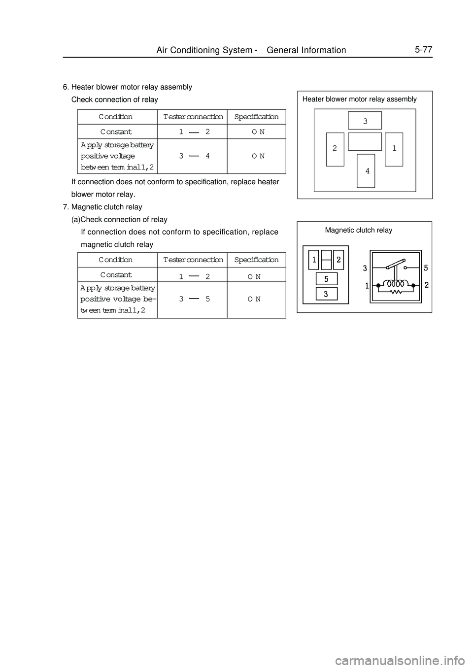
5-776. Heater blower motor relay assembly
Check connection of relayHeater blower motor relay assembly3
21
4 If connection does not conform to specification, replace heater
blower motor relay.
7. Magnetic clutch relay
(a)Check connection of relay
If connection does not conform to specification, replace
magnetic clutch relayCondition Tester connection Specification
Constant1 2 ON
3 4 ON Apply storage battery
positive voltage
between terminal 1, 2Condition Tester connection Specification
Constant
1 2 ON
3 5 ON Apply storage battery
positive voltage be-
tween terminal 1, 2Magnetic clutch relayAir Conditioning System -General Information
Page 265 of 416

Section 2 RefrigerantRefrigerant inspection1. Check refrigerant quantity
(a) Observe sight glass on refrigerating liquid pipe.
Test condition:
Engine speed: 1500 rpm
Blower speed control switch: HI "high "
Air conditioning switch: switch on
Temperature setting: maximum refrigeration
Refrigeration runs for 5 minutes
Open door
*: If refrigerating capacity is sufficient, environmental temperature is higher than normal condition, bubble
in sight glass may be deemed as normal.Symptom Refrigerant quantity Correct treatment2. Use manifold meter to check refrigerant pressure
( a ) This method is to utilize installed instrument to determine
where the fault is. Use manifold pressure meter reading to evaluate
fault condition.
Test condition:
Switch sets temperature of cyclical air inlet: 30-35°C
Engine speed: 1500 rpm
Blower speed control switch: high
Temperature control panel: refrigeration5-78With foam
Without foam
No temperature difference be-
tween input and output of
compressor
There is considerable tem-
perature difference between
compressor input and output
After air conditioner is turned
off, refrigerant should be
cleared immediately
After air conditioner is turned
off, refrigerant foams
immediately, then clears 1
2
3
4
5
6Insufficient *
Empty, insufficient or beyond
Empty or nearly full
Proper or beyond
Excess
Appropriate quantity1. Check gas leakage, repair if necessary
2. Add refrigerant until foam disappears
Refer to 3 and 4
1. Use detector to check gas leakage,
repair if necessary
2. Add refrigerant until foam disappears.
Refer to 5 and 6
1. Discharge refrigerant
2. Eliminate air, add appropriate quantity
of pure refrigerantSight glassAir Conditioning System -
Refrigerant