relay GENESIS G80 2017 User Guide
[x] Cancel search | Manufacturer: GENESIS, Model Year: 2017, Model line: G80, Model: GENESIS G80 2017Pages: 496, PDF Size: 12.82 MB
Page 451 of 496

7-74
Maintenance
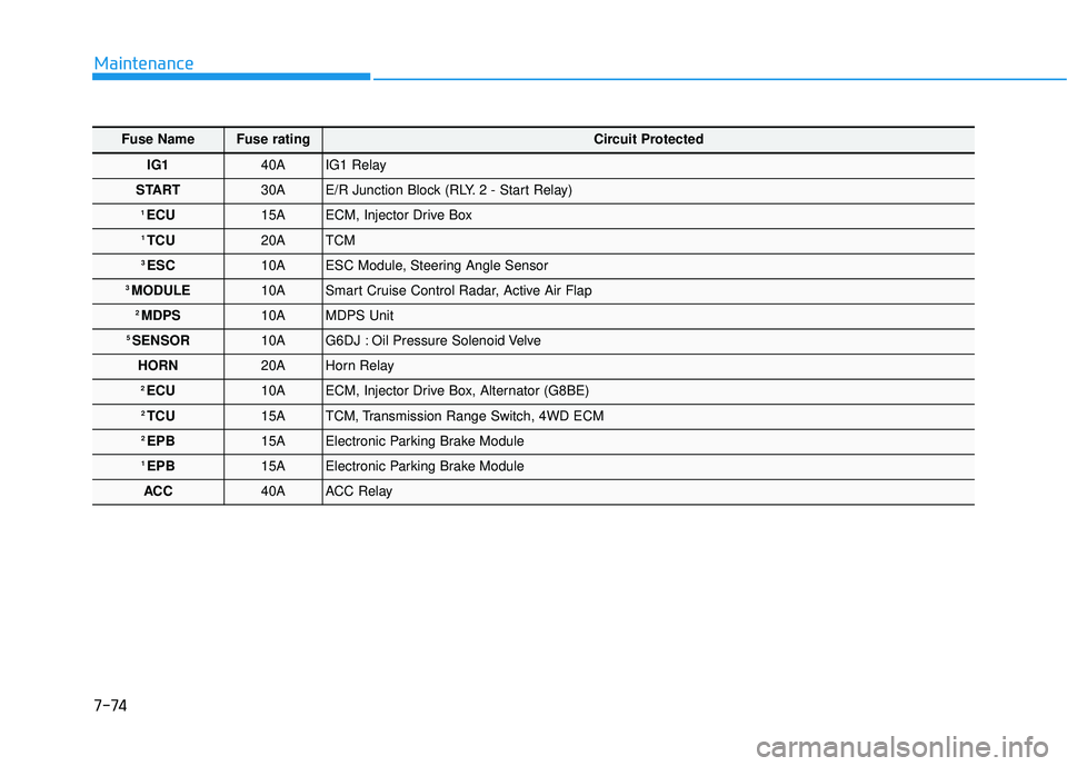
Fuse NameFuse ratingCircuit Protected
IG1 40A IG1 Relay
START 30A E/R Junction Block (RLY. 2 - Start Relay)
1 ECU15A ECM, Injector Drive Box
1 TCU20A TCM
3 ESC10A ESC Module, Steering Angle Sensor
3 MODULE 10A Smart Cruise Control Radar, Active Air Flap
2 MDPS10A MDPS Unit
5 SENSOR10A G6DJ : Oil Pressure Solenoid Velve
HORN 20A Horn Relay
2 ECU 10A ECM, Injector Drive Box, Alternator (G8BE)
2 TCU15A TCM, Transmission Range Switch, 4WD ECM
2 EPB15A Electronic Parking Brake Module
1 EPB15A Electronic Parking Brake Module
ACC 40A ACC Relay
Page 452 of 496

7-75
7
Maintenance
Trunk fuse panel (Rear fuse box panel)
Inside the fuse/relay box covers, you
can find the fuse/relay label describ-
ing fuse/relay name and capacity.
✽ ✽ NOTICE
Not all fuse panel descriptions in
this manual may be applicable to
your vehicle. It is accurate at the
time of printing. When you inspect
the fuse box on your vehicle, refer to
the fuse box label.ODH074052N
ODH073036
Page 453 of 496

7-76
Maintenance
Fuse NameFuse ratingCircuit Protected
P/TRUNK 30A Power Trunk Lid Control Module
P/DOOR RR RH 15A Rear Door Latch RH
2 DR LOCK15A Passenger Door Module
P/DOOR RR LH 15A Rear Door Latch LH
3 SPARE15A Spare Fuse
1 SPARE10A Spare Fuse
2 P/SEAT PASS 25A Passenger Power Seat Relay Box
F/LID 10A Fuel Lid Open Relay, Crash Pad Switch
ECS 15A ECS Unit
1 DR LOCK10A Driver Door Module
5 SPARE15A Spare Fuse
TRUNK 10A Trunk Lid Relay, Power Trunk Module Buzzer
S/HEATER RR RH 20A Rear Seat Warmer Control Module RH
FOG LAMP RR 10A Not Used
AMP 25A AMP
S/HEATER RR LH 20A Rear Seat Warmer Control Module LH
P/WDW RH 30A Passenger Power Window Module, Rear Power Window Module RH
F/PUMP 20A Fuel Pump Relay
RR HTD 40A Rear Defogger Relay
Page 454 of 496

7-77
7
Maintenance
Trunk fuse panel (Battery box fuse panel)
Inside the fuse/relay box covers, you
can find the fuse/relay label describ-
ing fuse/relay name and capacity.
✽ ✽ NOTICE
Not all fuse panel descriptions in
this manual may be applicable to
your vehicle. It is accurate at the
time of printing. When you inspect
the fuse box on your vehicle, refer to
the fuse box label.
ODH073037
ODH074038N
• Battery box fuse panel
Page 491 of 496

I-5
Fog light ........................................................................\
3-115
Front seats ........................................................................\
.2-6
Fuel filler door ................................................................3-59
Fuel gauge .......................................................................3\
-65
Fuel requirements .............................................................F-6
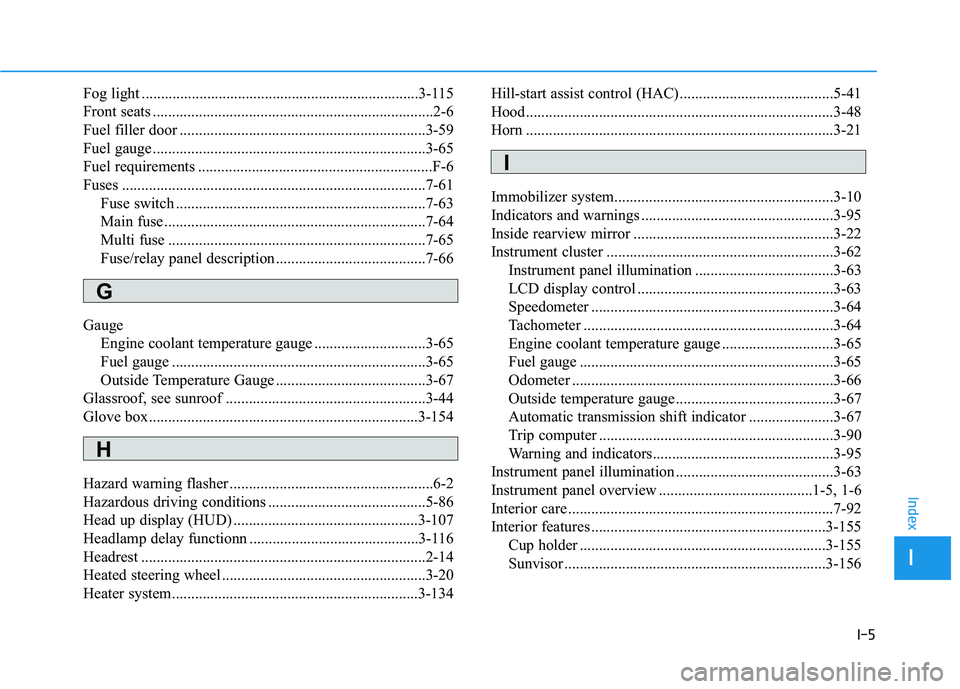
Fuses ........................................................................\
.......7-61Fuse switch .................................................................7-63
Main fuse ....................................................................7-64\
Multi fuse ...................................................................7-65
Fuse/relay panel description .......................................7-66
Gauge Engine coolant temperature gauge .............................3-65
Fuel gauge ..................................................................3-65
Outside Temperature Gauge .......................................3-67
Glassroof, see sunroof ....................................................3-44
Glove box......................................................................3-\
154
Hazard warning flasher .....................................................6-2
Hazardous driving conditions .........................................5-86
Head up display (HUD) ................................................3-107
Headlamp delay functionn ............................................3-116
Headrest ........................................................................\
..2-14
Heated steering wheel .....................................................3-20
Heater system................................................................3-134 Hill-start assist control (HAC)........................................5-41
Hood........................................................................\
........3-48
Horn ........................................................................\
........3-21
Immobilizer system.........................................................3-10
Indicators and warnings ..................................................3-95
Inside rearview mirror ....................................................3-22
Instrument cluster ...........................................................3-62
Instrument panel illumination ....................................3-63
LCD display control ...................................................3-63
Speedometer ...............................................................3-64
Tachometer .................................................................3-64
Engine coolant temperature gauge .............................3-65
Fuel gauge ..................................................................3-65
Odometer ....................................................................3-66\
Outside temperature gauge .........................................3-67
Automatic transmission shift indicator ......................3-67
Trip computer .............................................................3-90
Warning and indicators...............................................3-95
Instrument panel illumination .........................................3-63
Instrument panel overview ........................................1-5, 1-6
Interior care .....................................................................7-9\
2
Interior features .............................................................3-155 Cup holder ................................................................3-155
Sunvisor ....................................................................3-15\
6
I
Index
H
I
G