relay GENESIS G80 2017 Owner's Manual
[x] Cancel search | Manufacturer: GENESIS, Model Year: 2017, Model line: G80, Model: GENESIS G80 2017Pages: 496, PDF Size: 12.82 MB
Page 107 of 496

3-19
Convenient features of your vehicle
3
S
ST
T E
EE
ER
R I
IN
N G
G
W
W H
HE
EE
EL
L
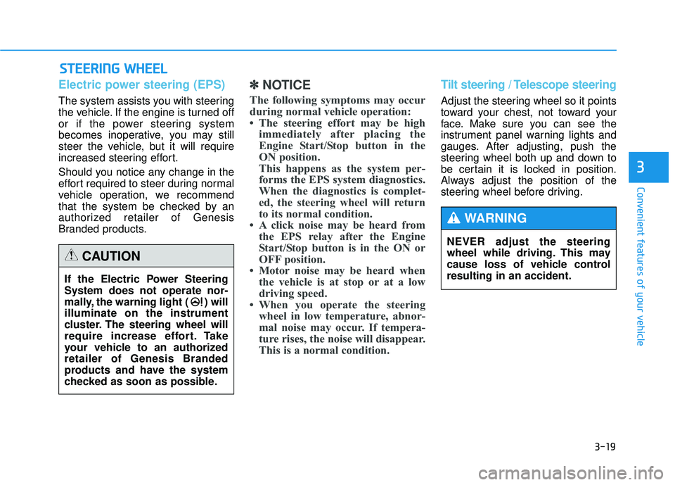
Electric power steering (EPS)
The system assists you with steering
the vehicle. If the engine is turned off
or if the power steering system
becomes inoperative, you may still
steer the vehicle, but it will require
increased steering effort.
Should you notice any change in the
effort required to steer during normal
vehicle operation, we recommend
that the system be checked by an
authorized retailer of Genesis
Branded products.
✽ ✽
NOTICE
The following symptoms may occur
during normal vehicle operation:
• The steering effort may be high
immediately after placing the
Engine Start/Stop button in the
ON position.
This happens as the system per-
forms the EPS system diagnostics.
When the diagnostics is complet-
ed, the steering wheel will return
to its normal condition.
• A click noise may be heard from the EPS relay after the Engine
Start/Stop button is in the ON or
OFF position.
• Motor noise may be heard when the vehicle is at stop or at a low
driving speed.
• When you operate the steering wheel in low temperature, abnor-
mal noise may occur. If tempera-
ture rises, the noise will disappear.
This is a normal condition.
Tilt steering / Telescope steering
Adjust the steering wheel so it points
toward your chest, not toward your
face. Make sure you can see the
instrument panel warning lights and
gauges. After adjusting, push the
steering wheel both up and down to
be certain it is locked in position.
Always adjust the position of the
steering wheel before driving.
If the Electric Power Steering
System does not operate nor-
mally, the warning light ( ) will
illuminate on the instrument
cluster. The steering wheel will
require increase effort. Take
your vehicle to an authorized
retailer of Genesis Branded
products and have the system
checked as soon as possible.
CAUTION
NEVER adjust the steering
wheel while driving. This may
cause loss of vehicle control
resulting in an accident.
WARNING
Page 379 of 496

7
Summer tires ....................................................................7-58\
Snow tires ........................................................................\
.7-58
Radial-ply tires ................................................................7-59
Low aspect ratio tires ....................................................7-59
Fuses ......................................................................7-\
61
Instrument panel fuse replacement ...........................7-62
Engine compartment panel fuse replacement.........7-64
Fuse/Relay panel description ......................................7-66
Light bulbs.............................................................7-79
Headlamp, position lamp, turn signal lamp, side
marker and front fog lamp bulb replacement .........7-79
Side repeater lamp replacement .................................7-83
Rear combination light bulb replacement .................7-83
High mounted stop lamp ...............................................7-85
License plate light bulb replacement .........................7-86
Interior light bulb replacement ....................................7-86
Appearance care ..................................................7-87
Exterior care ....................................................................7-87\
Interior care......................................................................7-\
92
Emission control system .....................................7-94
California perchlorate notice .............................7-98
Page 443 of 496

7-66
Maintenance
Fuse/Relay panel description
Instrument panel fuse panel
Inside the fuse/relay box cover, you
can find the fuse/relay label describ-
ing fuse/relay name and capacity.
✽ ✽NOTICE
Not all fuse panel descriptions in
this manual may be applicable to
your vehicle; the information is
accurate at the time of printing.
When you inspect the fuse box on
your vehicle, refer to the fuse box
label.
ODH073035
ODH074051N
Page 444 of 496

7-67
7
Maintenance
Instrument panel fuse panel
Fuse NameFuse ratingCircuit Protected
P/HANDLE 15A Steering Tilt & Telescopic Module
3MEMORY10A Passenger Power Outside Mirror
CLUSTER 10A Instrument Cluster, Head-Up Display
GATEWAY 10A Gateway (IG1 (MCU))
A/BAG IND 10A Instrument Cluster, A/C Control Module
3 SMART KEY10A Smart Key Control Module
3 MODULE10A BCM, Sport Mode Switch, Stop Lamp Switch, Driver/Passenger Door Module, Rear Door Module LH/RH
S/HEATER PASS 20A Passenger CCS Module, Passenger Seat Warmer Control Module
2MEMORY 10A Driver Power Outside Mirror
1MULTI MEDIA20A Fuse - MULTIMEDIA 2, A/V & Navigation Head Unit
B/A HORN 10A Burglar Alarm Horn Relay
9MODULE10A Multifunction Switch
4MODULE 10A
Steering Tilt & Telescopic Module, Blind Spot Detection Radar LH/RH Crash Pad Switch,
Tire Pressure Monitoring Module, Console Switch LH/RH, Front Parking Assist Sensor LH/RH,
Front Parking Assist Sensor (Center), ECS Unit, Electronic Parking Brake Switch,
Rear Parking Assist Sensor LH/RH, Rear Parking Assist Sensor (Center), LKAS Module
5MODULE 10A Multipurpose Check Connector, A/V & Navigation Head Unit, Electro Chromic Mirror, A/C Control Module,
I-Box, AMP, Driver/Passenger CCS Module, Driver Power Seat Switch, Driver/Passenger Seat Warmer
Control Module, Rear Seat Warmer Control Module LH/RH, Driver IMS Control Module
Page 445 of 496

7-68
Maintenance
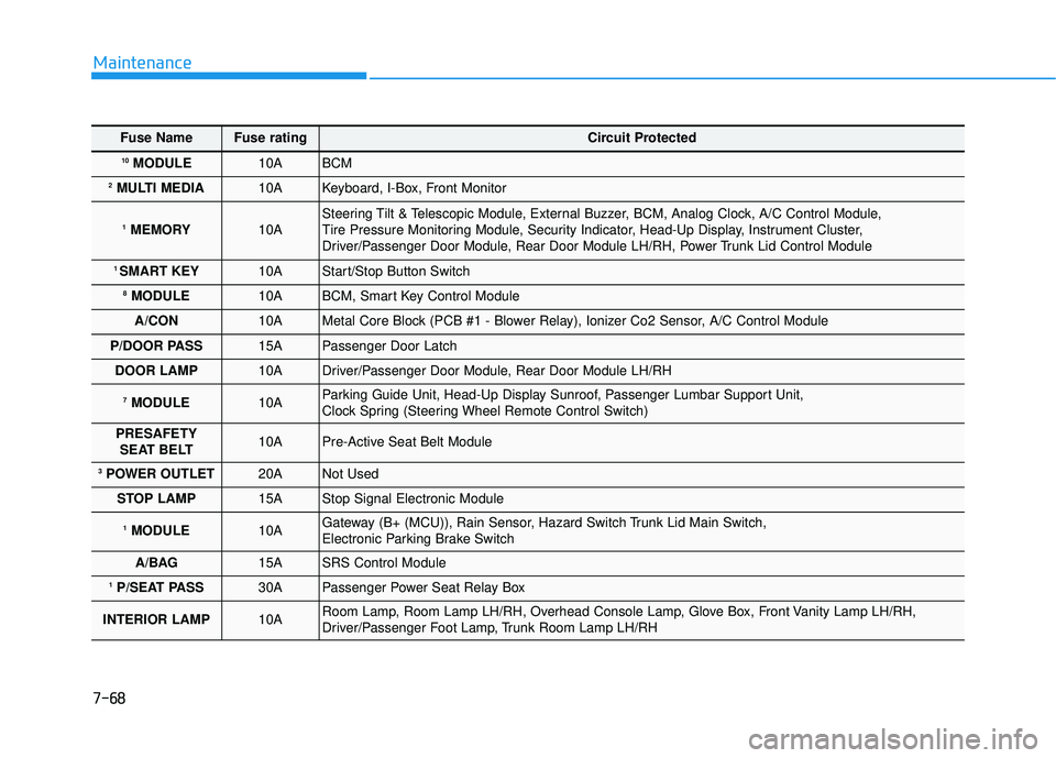
Fuse NameFuse ratingCircuit Protected
10MODULE10A BCM
2MULTI MEDIA 10A Keyboard, I-Box, Front Monitor
1MEMORY10A Steering Tilt & Telescopic Module, External Buzzer, BCM, Analog Clock, A/C Control Module,
Tire Pressure Monitoring Module, Security Indicator, Head-Up Display, Instrument Cluster,
Driver/Passenger Door Module, Rear Door Module LH/RH, Power Trunk Lid Control Module
1 SMART KEY10A Start/Stop Button Switch
8MODULE10A BCM, Smart Key Control Module
A/CON 10A Metal Core Block (PCB #1 - Blower Relay), Ionizer Co2 Sensor, A/C Control Module
P/DOOR PASS 15A Passenger Door Latch
DOOR LAMP 10A Driver/Passenger Door Module, Rear Door Module LH/RH
7MODULE 10A Parking Guide Unit, Head-Up Display Sunroof, Passenger Lumbar Support Unit,
Clock Spring (Steering Wheel Remote Control Switch)
PRESAFETY SEAT BELT 10A Pre-Active Seat Belt Module
3POWER OUTLET 20A Not Used
STOP LAMP 15A Stop Signal Electronic Module
1MODULE10A Gateway (B+ (MCU)), Rain Sensor, Hazard Switch Trunk Lid Main Switch,
Electronic Parking Brake Switch
A/BAG 15A SRS Control Module
1P/SEAT PASS 30A Passenger Power Seat Relay Box
INTERIOR LAMP 10A Room Lamp, Room Lamp LH/RH, Overhead Console Lamp, Glove Box, Front Vanity Lamp LH/RH,
Driver/Passenger Foot Lamp, Trunk Room Lamp LH/RH
Page 446 of 496

7-69
7
Maintenance
Fuse NameFuse ratingCircuit Protected
2SMART KEY15A Smart Key Control Module
1 POWER OUTLET 20A Front Power Outlet & Cigarette Lighter
6MODULE 15A Head Lamp LH/RH, Auto Hold & Drive Mode Switch, Auto Head Lamp Leveling Device Module, A/T Shift
Lever IND.
P/WDW LH 30A Driver Power Window Module, Rear Door Module LH, Rear Power Window Module LH
SUNROOF 25A Sunroof Motor
BRAKE SWITCH 10A Stop Lamp Switch, Smart Key Control Module
2POWER OUTLET 20A Front Power Outlet & Cigarette Lighter
HTD STRG 15A Clock Spring (Steering Wheel Heated Module)
1P/SEAT DRV 30A Driver IMS Control Module, Driver Power Seat Relay Box
P/DOOR DRV 15A Driver Door Latch
2MODULE10A BCM, Smart Key Control Module, Overhead Console Lamp, Analog Clock, A/V & Navigation Head Unit,
Keyboard, I-Box, Front Monitor, Parking Guide Unit
Page 447 of 496

7-70
Maintenance
Engine compartment fuse panel
Inside the fuse/relay box cover, you
can find the fuse/relay label describ-
ing fuse/relay name and capacity.
✽ ✽NOTICE
Not all fuse panel descriptions in
this manual may be applicable to
your vehicle; the information is
accurate at the time of printing.
When you inspect the fuse panel in
your vehicle, refer to the fuse panel
label.
ODH073033
ODH073034
Page 448 of 496

7-71
7
Maintenance
Engine compartment main fuse panel
Fuse NameFuse ratingCircuit Protected
ALT200AAlternator, Multifuse (BATT) - B+2/ B+5/ MDPS 1/ C/FAN, Fuse - P/SEAT DRV 2/ P/SEAT RR/ SEAT
LUMBAR/ ESC 1/ ESC 2
1 B+ 60A IGPM (Fuse - BRAKE SWITCH, Leak Current Autocut Device (Fuse - INTERIOR LAMP/ MULTI MEDIA 1/
MEMORY 1/ MEMORY 2/ MEMORY 3), IPS 1)
3B+ 60A IGPM (Fuse - SMART KEY 1/ SMART KEY 2/ MODULE 1/ B/A HORN, IPS 2/IPS 3/IPS 5/IPS 7)
4B+60A IGPM (Fuse - DOOR LAMP/ STOP LAMP, IPS 4/IPS 6)
6B+60A Metal Core Block (PCB #1 Fuse - ECU 3/ IG2/ MODULE 1)
7B+80A Metal Core Block (PCB #2 Fuse - HORN/ ACC/ EPB 1/ EPB 2)
2 B+ 60A IGPM (Fuse - P/HANDLE/ P/WDW LH/ P/SEAT PASS 1/ S/HEATER PASS/ MODULE 10/ SUNROOF/
P/DOOR DRV/ P/DOOR PASS)
C/FAN 70A RLY. 1 (C/Fan Relay)
5 B+ 80A Metal Core Block (PCB #1 Fuse - BLOWER/ DEICER/ H/LAMP WASHER)
MDPS 1 125A MDPS Unit
B/UP LAMP 10A TCM, Transmission Range Switch, Rear Combination Lamp (IN) LH/RH, Electro Chr\
omic Mirror, A/V &
Navigation Head Unit
P/SEAT RR 30A Not Used
1 ESC40A ESC Module, Multipurpose Check Connector
2 ESC40A ESC Module, Multipurpose Check Connector
Page 449 of 496

7-72
Maintenance
Fuse NameFuse ratingCircuit Protected
SEAT LUMBAR 10A Driver/Passenger Power Seat Relay Box, Driver/Passenger Lumbar Support Unit
2P/SEAT DRV 25A Driver IMS Control Module, Driver Power Seat Switch, Driver Power Seat Relay Box
ACTIVE
HOOD LH 30A Not Used
ACTIVE
HOOD RH 30A Not Used
WIPER30A Wiper Motor
S/HEATER DRV 25A Driver CCS Module, Driver Seat Warmer Control Module
4WD 30A 4WD ECM
1 PRESAFETY SEAT BELT30A Pre-Active Seat Belt Module
2 PRESAFETYSEAT BELT30A Pre-Active Seat Belt Module
H/LAMP HI SOL 10A Metal Core Block (PCB #2 - Head Lamp High Solenoid Relay)
Page 450 of 496

7-73
7
Maintenance
Fuse NameFuse ratingCircuit Protected
IG230A IG2 Relay
3ECU30A Engine Control Relay
1 MODULE 10A 4WD ECM, Smart Cruise Control Radar, Active Air Flap
2WIPER10A Metal Core Block (PCB #2 - Wiper Relay)
WASHER 20A Washer Relay
2SENSOR 10A ECM, Oxygen Sensor #1/#2/#3/#4
1 SENSOR10A ECM, Oil Control Valve #1/#2/#3/#4, Canister Close Valve, Purge Control Solenoid Valve, Variable Intake
Solenoid Valve #1/#2
3 SENSOR10A ECM, Rear Junction Block (Fuel Pump Relay)
4 SENSOR10A C/Fan Relay, Camshaft Position Valve (G8BE)
INJECTOR 15A Injector Drive Box
IGN COIL 20A G6DJ : Condenser, Ignition Coil #1/#2/#3/#4/#5/#6, G8BE : Condenser #1/#2, Ignition Coil
#1/#2/#3/#4/#5/#6/#7/#8
DEICER 20A Metal Core Block (PCB #2 - Front Deicer Relay)
H/LAMP WASHER 25A Head Lamp Washer Relay
2A/CON10A A/C Control Module
BLOWER 40A Blower Relay