clock GENESIS G80 2021 User Guide
[x] Cancel search | Manufacturer: GENESIS, Model Year: 2021, Model line: G80, Model: GENESIS G80 2021Pages: 604, PDF Size: 11.47 MB
Page 505 of 604

08
8-13
IF YOU HAVE A FLAT TIRE (WITH SPARE TIRE, IF EQUIPPED)
WARNING
Changing a tire can be dangerous.
Follow the instructions in this section
when changing a tire to reduce the risk
of serious injury or death.
CAUTION
Be careful as you use the jack handle to
stay clear of the flat end. The flat end
has sharp edges that could cause cuts.
Jack and Tools
ORG3080043L
1. Jack handle
2. Jack
3. Wheel lug wrench
4. Centering pin
5. Towing hook
The jack, jack handle, and wheel lug
wrench are stored in the luggage
compartment under the luggage box
cover.
The jack is provided for emergency tire
changing only.
ORG3080044L
Turn the winged hold down bolt
counterclockwise to remove the spare
tire.
Store the spare tire in the same
compartment by turning the winged hold
down bolt clockwise.
To prevent the spare tire and tools from
“rattling”, store them in their proper
location.
ORG3080045L
If it is hard to loosen the tire hold-down
wing bolt by hand, you can loosen
it easily using the wheel lug wrench
(1). Turn the tire hold-down wing bolt
counterclockwise with the wheel lug
wrench.
Page 507 of 604

08
8-15
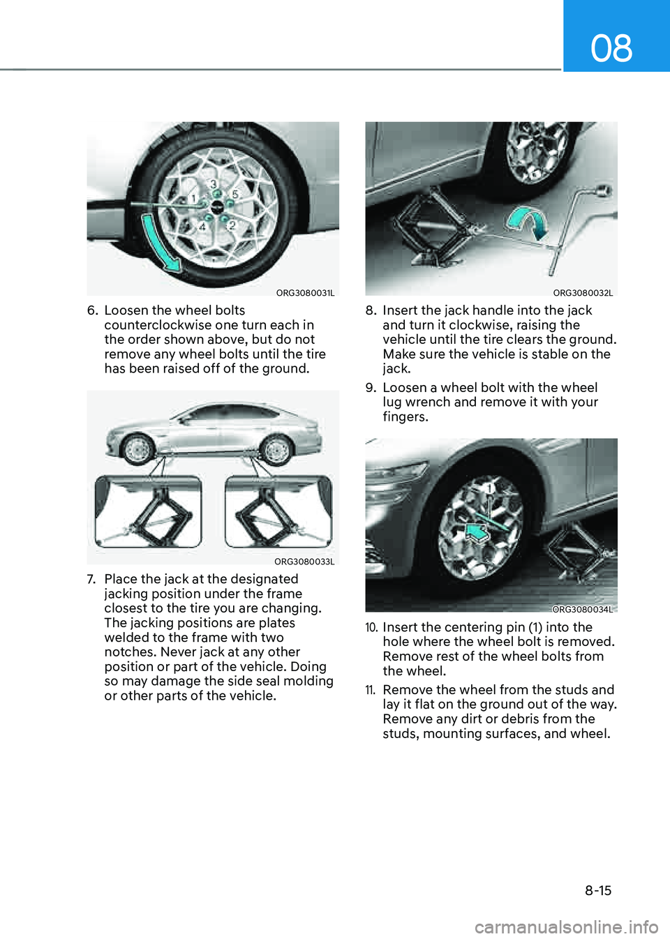
ORG3080031L
6. Loosen the wheel bolts
counterclockwise one turn each in
the order shown above, but do not
remove any wheel bolts until the tire
has been raised off of the ground.
ORG3080033L
7. Place the jack at the designated
jacking position under the frame
closest to the tire you are changing.
The jacking positions are plates
welded to the frame with two
notches. Never jack at any other
position or part of the vehicle. Doing
so may damage the side seal molding
or other parts of the vehicle.
ORG3080032L
8. Insert the jack handle into the jack
and turn it clockwise, raising the
vehicle until the tire clears the ground.
Make sure the vehicle is stable on the
jack.
9. Loosen a wheel bolt with the wheel
lug wrench and remove it with your
fingers.
ORG3080034L
10. Insert the centering pin (1) into the
hole where the wheel bolt is removed.
Remove rest of the wheel bolts from
the wheel.
11. Remove the wheel from the studs and
lay it flat on the ground out of the way.
Remove any dirt or debris from the
studs, mounting surfaces, and wheel.
Page 508 of 604

Emergency Situations
8-16
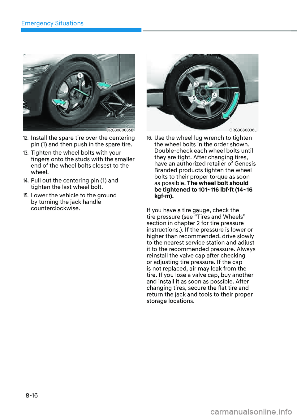
ORG3080035L
12. Install the spare tire over the centering
pin (1) and then push in the spare tire.
13. Tighten the wheel bolts with your
fingers onto the studs with the smaller
end of the wheel bolts closest to the
wheel.
14. Pull out the centering pin (1) and
tighten the last wheel bolt.
15. Lower the vehicle to the ground
by turning the jack handle
counterclockwise.
ORG3080036L
16. Use the wheel lug wrench to tighten
the wheel bolts in the order shown.
Double-check each wheel bolts until
they are tight. After changing tires,
have an authorized retailer of Genesis
Branded products tighten the wheel
bolts to their proper torque as soon
as possible. The wheel bolt should
be tightened to 101~116 lbf·ft (14~16
kgf·m).
If you have a tire gauge, check the
tire pressure (see “Tires and Wheels”
section in chapter 2 for tire pressure
instructions.). If the pressure is lower or
higher than recommended, drive slowly
to the nearest service station and adjust
it to the recommended pressure. Always
reinstall the valve cap after checking
or adjusting tire pressure. If the cap
is not replaced, air may leak from the
tire. If you lose a valve cap, buy another
and install it as soon as possible. After
changing tires, secure the flat tire and
return the jack and tools to their proper
storage locations.
Page 513 of 604

08
8-21
When towing your vehicle in an emergency without wheel dollies:
1. Release EPB before turning off the
engine.
2. Press the Engine Start/Stop button to
the OFF position.
3. Change the gear to N (Neutral) by
pressing the P release button (need to
remove cap-cover) while pressing the
brake pedal. For more details, refer to
“Automatic Transmission” section in
chapter 6.
4. Press the Engine Start/Stop button to
the ACC position.
CAUTION
Failure to shift the gear to N (Neutral)
may cause internal damage to the
transmission.
Removable Towing Hook
1. Open the trunk, and remove the
towing hook from the tool case.
„„Front
ORG3080021
„„Rear
ORG3080018
2. Remove the hole cover by pressing
the lower part of the cover on the
bumper.
3. Install the towing hook by turning it
clockwise into the hole until it is fully
secured.
4. Remove the towing hook and install
the cover after use.
Page 534 of 604

09
9-19
WARNING
Never remove the engine coolant radiator cap, coolant
cap or the drain plug while
the engine and radiator are
hot. Hot coolant and steam
may blow out under pressure,
causing serious injury.
Turn the vehicle off and wait until
the engine cools down. Use extreme
care when removing the radiator cap,
coolant cap. Wrap a thick towel around
it, and turn it counterclockwise slowly
to the first stop. Step back while the
pressure is released from the cooling
system. When you are sure all the
pressure has been released, press down
on the cap, using a thick towel, and
continue turning counterclockwise to
remove it.
Information
The coolant level is influenced by the
engine temperature. Before checking or
refilling the coolant, turn the engine off.
WARNING
The electric motor for the cooling fan may continue to
operate or start up when the
engine is not running and can
cause serious injury. Keep
hands, clothing and tools away
from the rotating fan blades of
the cooling fan.
Always turn off the vehicle unless the
vehicle has to be inspected with the
engine on. Be cautious as the cooling
fan may operate if the negative (-)
battery terminal is not disconnected.
WARNING
Make sure the coolant cap is properly
closed after refilling coolant. Otherwise
the engine could be overheated while
driving.
„„Engine compartment front view
OOSH089010L
1. Check if the coolant cap label is
straight in front.
OJX1099046
2. Make sure that the tiny protrusions
inside the coolant cap is securely
interlocked.
Page 544 of 604

09
9-29
• The negative battery cable must
be removed first and installed last
when the battery is disconnected.
Disconnect the battery charger in the
following order:
1. Turn off the battery charger main
switch.
2. Unhook the negative clamp from
the negative battery terminal.
3. Unhook the positive clamp from
the positive battery terminal.
• Always use a Genuine Genesis Part
approved battery when you replace
the battery.
NOTICE
AGM battery
• Absorbent Glass Matt (AGM)
batteries are maintenance-free and
we recommend that the AGM battery
be serviced by an authorized retailer
of Genesis Branded products. For
charging your AGM battery, use only
fully automatic battery chargers that
are specially developed for AGM
batteries.
• When replacing the AGM battery,
we recommend that you use parts
for replacement from an authorized
retailer of Genesis Branded products.
• Do not open or remove the cap on
top of the battery. This may cause
leaks of internal electrolyte that
could result in severe injury.
By jump starting
After a jump start from a good battery,
drive the vehicle for 20-30 minutes
before it is shutoff. The vehicle may
not restart if you shut it off before the
battery had a chance to adequately
recharge. See “Jump Starting” in chapter
6 for more information on jump starting
procedures.
Information
An inappropriately disposed battery can be harmful to the
environment and human health.
Dispose of the battery according
to your local law(s) or regulation.
Reset Items
The following items may need to be reset
after the battery has been discharged or
the battery has been disconnected.
• Fuel economy/Driving info/Since
refueling/Accumulated info (items in
Utility view) (see chapter 4)
• Integrated memory system (see
chapter 5)
• Power window (see chapter 5)
• Sunroof (see chapter 5)
• Power trunk (see chapter 5)
• Climate control system (see chapter 5)
• Rear door window shade (see chapter
5)
• Clock (see Infotainment system
manual)
• Infotainment system (see
Infotainment system manual)
Page 563 of 604

Maintenance
9-48
Instrument panel fuse panel
Fuse NameFuse Rating Circuit Protected
MODULE8 10ARear Radar LH/RH, ECS Unit, RWS Module, ADAS Unit
(Driving), ADAS Unit (Parking), Crash Pad Switch, Front
Console Switch, Steering Tilt & Telescopic Unit, LKAS Unit
MODULE5 10A
ICU Junction Block (ESU), Hazard Switch
MODULE3 10ARear Seat Console Remote Control Switch Switch, Active
Air Flap Module, Clock Spring, Steering Tilt & Telescopic
Unit, Multifunction Switch
P/WINDOW LH 30ADriver Power Window Module, Rear Power Window Module
LH
CURTAIN 10A
IBU
P/SEAT PASS2 25A
Passenger Power Seat Module
TRUNK 10A
Trunk Release Relay
AIR BAG1 15A
SRS Control Module
E-SHIFTER1 10A
Electronic ATM Shift Lever Dial
MODULE4 10A
Driver Door Module, Data Link Connector
P/SEAT DRV1 25A
Driver Power Seat Module
P/SEAT 10A
Driver/Passenger Lumbar Support Unit (3/5/7CELL)
POWER
HANDLE 15A
Steering Tilt & Telescopic Unit
IBU1 10AIAU, IBU, BLE Unit, Driver Door Outside Handle, Passenger
Door Outside Handle
POWER
OUTLET 20A
Armrest Power Outlet
P/SEAT DRV2 25A
Driver Power Seat Module
P/SEAT PASS1 25A
Passenger Power Seat Module
S/HEATER DRV 20A
Driver Power Seat Module
S/HEATER PASS 20A
Passenger Power Seat Module
DOOR LOCK 10A
Center Door Lock/Unlock Relay, Driver Door Unlock Relay
SPARE(B+) 10A
Not Used
MODULE6 10AArmrest Lamp, IBU, Low DC-DC Converter(AUX/AMP),
Electronic ATM Shift Lever Dial, Front Tray Lamp, IAU,
BRAKE SWITCH 10A
Stop Lamp Switch, IBU
Page 597 of 604

IndexI-8
Infotainment System ........................................................................\
..................5-125
Antenna
........................................................................\
.................................5-125
Bluetooth® Wireless Technology
.................................................................5-127
Infotainment System
........................................................................\
.............5-126
Lexicon Premium Sound System
.................................................................5-127
Steering Wheel Remote Controls
..................................................................5-125
USB Port
........................................................................\
...............................5-125
Voice Recognition
........................................................................\
.................5-126
Instrument Cluster
........................................................................\
.........................4-4
Gauges and Meters
........................................................................\
....................4-5
Instrument Cluster Control
........................................................................\
........4-5
LCD Display Messages
........................................................................\
...........4-22
Transmission Shift Indicator
........................................................................\
...4-10
Warning and Indicator Lights
........................................................................\
..4-11
Instrument Panel Overview (I)
........................................................................\
......2-5
Instrument panel Overview (III)
........................................................................\
....2-6
Integrated Memory System ........................................................................\
.......... 5-34
Recalling Memory Positions
........................................................................\
...5-35
Resetting the System
........................................................................\
...............5-35
Seat Easy Access
........................................................................\
.....................5-36
Storing Memory Positions ........................................................................\
....... 5-34
Interior Features
........................................................................\
.........................5-116
Clock
........................................................................\
.....................................5-121
Coat Hook
........................................................................\
.............................5-121
Cup Holder
........................................................................\
............................5-116
Floor Mat Anchor(s)
........................................................................\
..............5-122
Luggage Net Holder
........................................................................\
.............5-124
Power Outlet ........................................................................\
.......................... 5-118
Rear Mirror ........................................................................\
........................... 5-117
Rear Side Window Sunshades
......................................................................5-123
Rear Window Sunshade
........................................................................\
.......5-123
Sunvisor ........................................................................\
................................. 5-117
USB Charger
........................................................................\
.........................5-119
Wireless Smart Phone Charging System
......................................................5-119
Interior Overview (I) ........................................................................\
...................... 2-4