GMC SAVANA 1996 Owners Manual
Manufacturer: GMC, Model Year: 1996, Model line: SAVANA, Model: GMC SAVANA 1996Pages: 372, PDF Size: 18.81 MB
Page 111 of 372
Check Gages Light
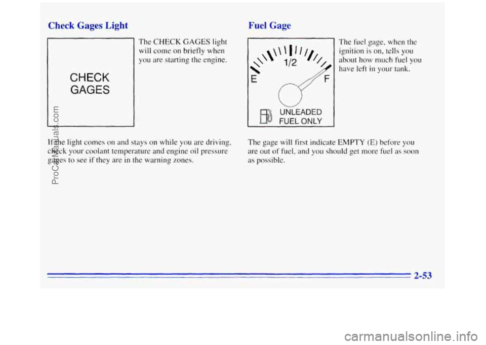
The CHECK GAGES light
will come on briefly when
you are starting
the engine.
CHECK
GAGES
Fuel Gage
*
\\'
E
FUEL ONLY
UNLEADED
The fuel gage, when the
ignition is on, tells you
about how much
fuel you
have left
in your tank.
If the light comes on and stays on while you are dri\iing,
check your coolant temperature and engine oil pressure
gages to see
if they are in the warning zones. The
gage will first indicate
EMPTY (E) before you
are out
of fuel, and you should get more fuel as soon
as
possible.
2-53
ProCarManuals.com
Page 112 of 372
Listed are four situations you may experience with your
fuel gage:
0
0
0
0
At the gas station, the fuel pump shuts off before the
gage reads
FULL (F).
It takes a little more or less fuel to fill up than the
fuel gage indicated. For example, the gage may have
indicated the tank was half
full, but it actually took a
little more or less than half the tank’s capacity to fill
the tank.
The gage moves a little when
you turn a corner or
speed
up.
The gage doesn’t go back to EMPTY (E) when you
turn off the ignition.
None
of these indicate a problem with the fuel gage.
Engine Coolant Temperature Gage
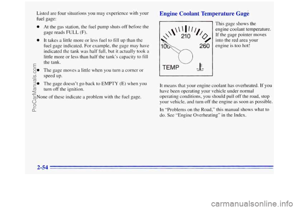
This gage shows the
If the gage pointer moves /I,
engine coolant temperature.
o/ into the red area your
260 engine is too hot!
TEMP -FA mr
It means that your engine coolant has overheated. If you
have been operating your vehicle under normal
operating conditions, you should pull off the road, stop
your vehicle, and
turn off the engine as soon as possible.
In “Problems on the Road,” this manual shows what to
do. See ”Engine Overheating”
in the Index.
2-54
ProCarManuals.com
Page 113 of 372
Voltmeter
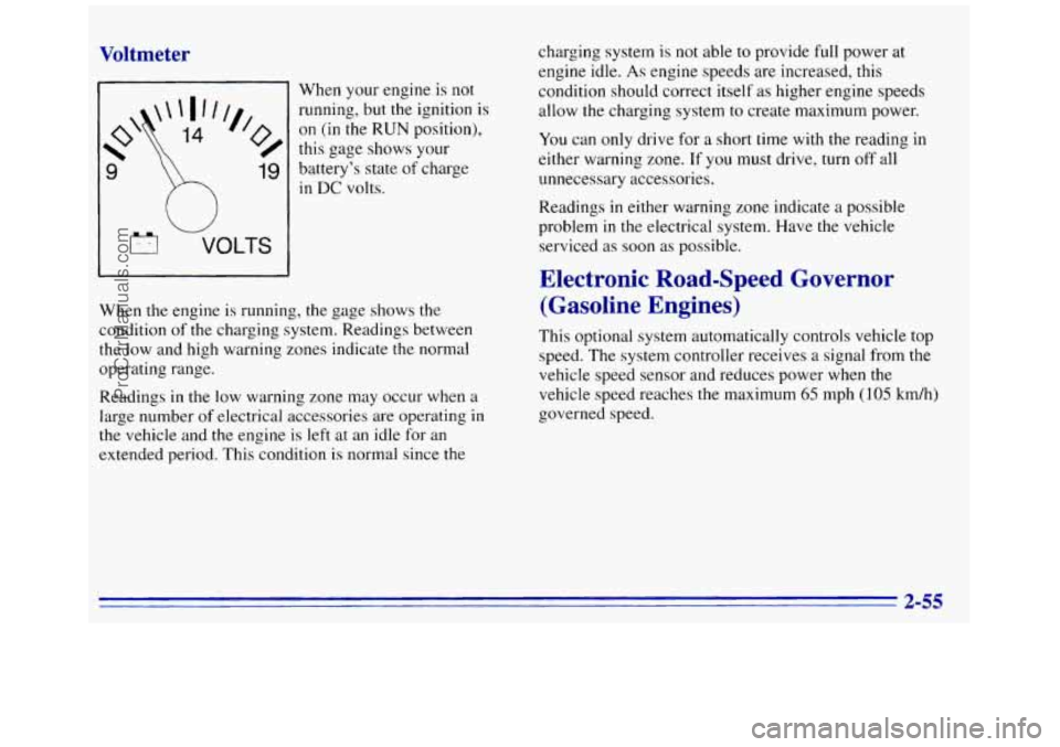
When your engine is not
running, but the ignition
is
on (in the RUN position),
this gage shows your
9
h
19 battery’s state of charge
in DC volts.
u
VOLTS
When the engine is running, the gage shows the
condition of
the charging system. Readings between
the low and high warning zones indicate the normal
operating range.
Readings
in the low warning zone may occur when a
large number of electrical accessories are operating in
the vehicle and the engine is left at an idle for an
extended period. This conditi.on is normal since the charging
system
is not able to provide full power at
engine idle.
As engine speeds are increased, this
condition should correct itself as higher engine speeds
allow
the charging system to create maximum power.
You can only drive for
a short time with the reading in
either warning zone. If you must drive, turn
off all
unnecessary accessories.
Readings
in either warning zone indicate a possible
problem in the electrical system. Have the vehicle
serviced
as soon as possible.
Electronic Road-Speed Governor (Gasoline Engines)
This optional system automatically controls vehicle top
speed. The system controller receives
a signal from the
vehicle speed sensor and reduces power when the
vehicle speed reaches
the maximum 65 mph (105 km/h)
governed speed.
2-55
ProCarManuals.com
Page 114 of 372
‘Center High-Mounted Stoplamp
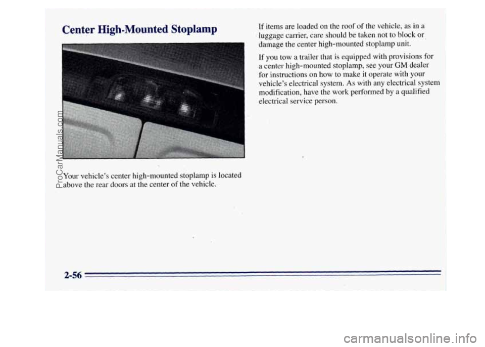
Your vehicle’s center high-mounted stoplamp is located
above the rear doors at the center of the vehicle.
If items are loaded on the roof of the vehicle, as in a
’ luggage carrier, care should be taken not to block or
damage the center high-mounted stoplamp unit.
If
you tow a trailer that is equipped with provisions for
a center high-mounted stoplamp, see your
GM dealer
for instructions on how to make it operate with your
vehicle’s electrical system.
As with any electrical system
modlfication, have the work performed
by a qualified
electrical service person.
I
2-56 I
ProCarManuals.com
Page 115 of 372
NOTES
2-57
ProCarManuals.com
Page 116 of 372
NOTES
3 LQ
ProCarManuals.com
Page 117 of 372
Section 3 Comfort Controls and Audio Systems
In this section you’ll find out how to operate the comfort
control and audio systems offered with your vehicle. Be
sure to read about the particular systems supplied with
your vehicle.
Comfort Controls
This section tells you how to make your air system work
for you. Your comfort control system uses
ozone-friendly
R- I34a refrigerant.
With these systems, you can control the heating,
cooling and ventilation
in your van. Your vehicle also
has a flow-through ventilation system described later in
this section.
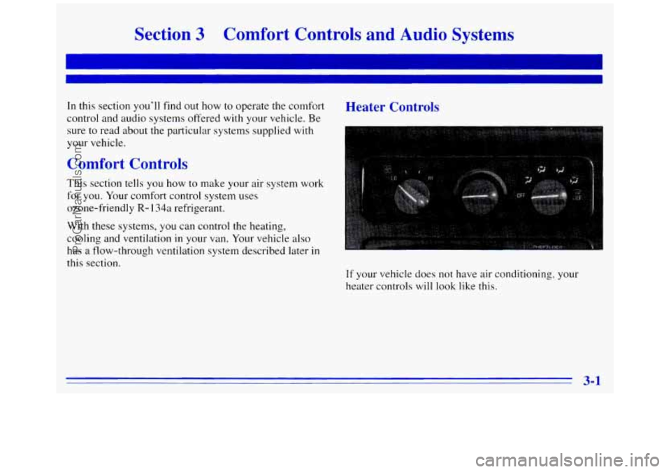
Heater Controls
If your vehicle does not have air conditioning, your
heater controls
will look like this.
3-1
ProCarManuals.com
Page 118 of 372
Fan Knob Mode Knob
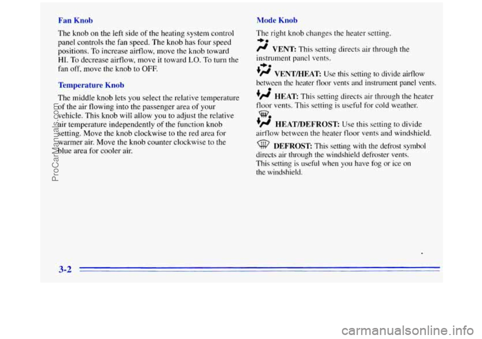
The knob on the left
side of the heating system control
panel controls the fan speed. The knob has four speed
positions. To increase airflow, move the knob toward
HI. To decrease airflow, move it toward LO. To turn the
fan
off, move the knob to OFF.
Temperature Knob
The middle knob lets you select the relative temperature
of the air flowing into the passenger area of your
vehicle. This knob will allow
you to adjust the relative
air temperature independently of the function knob
setting. Move
the knob clockwise to the red area for
warmer air. Move the knob counter clockwise to
the
blue area for cooler air. The right knob changes
the heater set.ting.
/J VENT This sett.ing directs air through the
instrument panel vents.
'/J VENTMEAT Use this setting to divide airflow
between
the heater floor vents and instrument panel vents.
+# HEAT: This setting directs air through the heater
floor vents. This setting is useful
for cold weather.
+' HEATPDEFROST: Use this setting to divide
airflow between the heater floor vents and windshield.
+e
+e
e
we
DEFROST: This setting with the defrost symbol
directs air through the windshield defroster vents.
This setting
is useful when you have fog or ice on
the windshield.
3-2
ProCarManuals.com
Page 119 of 372
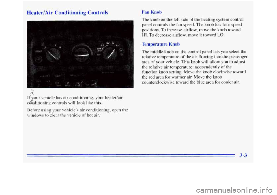
Heater/Air Conditioning Controls
.-
If your vehicle has air conditioning, your heater/air
conditioning controls
will look like this.
Before using your vehicle's air conditioning, open the
windows to clear the vehicle
of hot air.
Fan Knob
The knob on the left side of the heating system control
panel controls the
fdn speed. The knob has four speed
positions.
To increase airflow, move the knob toward
HI. To decrease airflow, move it toward LO.
Temperature Knob
The middle knob on the control panel lets you select the
relative temperature
of the air flowing into the passenger
area
of your vehicle. This knob will allow you to adjust
the relative air temperature independently
of the
function knob setting. Move the
knob clockwise toward
the red area for warmer air. Move the knob
counterclockwise toward the blue area for cooler air.
3-3
ProCarManuals.com
Page 120 of 372
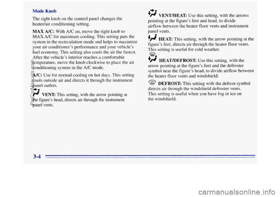
Mode Knob
The right knob on the control panel changes the
heatedair conditioning setting.
MAX NC: With A/C on, move the right knob to
MAX A/C for maximum cooling. This setting puts the
system in the recirculation mode and helps
to maximize
your air conditioner’s performance and your vehicle’s
fuel economy. This setting also cools the air
the fastest.
After the vehicle’s interior reaches
a comfortable
temperature, move the
knob clockwise to place the air
conditioning system in the
A/C mode.
A/C: Use for normal cooling on hot days. This setting
cools outside air and directs
it through the instrument
panel
outlets.
-bo
fl VENT This setting, with the arrow pointing at
the figure’s head, directs
air through the instrument
panel vents.
+e
’# VENT/HEAT Use this setting, with the arrows
pointing at the figure’s feet and head, to divide
airflow between the heater floor vents and instrument
panel vents.
+fl HEAT This setting, with the arrow pointing at the
figure’s feet, directs air through the heater floor vents.
This setting is useful for cold weather.
+’ HEAT/DEFROST Use this setting, with the
arrow pointing at the figure’s feet and
the defroster
symbol near the figure’s head, to divide airflow between
the heater floor
vents and windshield.
e
we
DEFROST This setting with the defrost symbol
directs air through the windshield defroster vents.
This setting is useful when
you have fog or ice on
the windshield.
3-4
ProCarManuals.com