clock GMC SIERRA 2010 Owner's Guide
[x] Cancel search | Manufacturer: GMC, Model Year: 2010, Model line: SIERRA, Model: GMC SIERRA 2010Pages: 630, PDF Size: 4.65 MB
Page 458 of 630
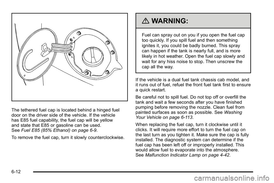
The tethered fuel cap is located behind a hinged fuel
door on the driver side of the vehicle. If the vehicle
has E85 fuel capability, the fuel cap will be yellow
and state that E85 or gasoline can be used.
SeeFuel E85 (85% Ethanol) on page 6‑9.
To remove the fuel cap, turn it slowly counterclockwise.
{WARNING:
Fuel can spray out on you if you open the fuel cap
too quickly. If you spill fuel and then something
ignites it, you could be badly burned. This spray
can happen if the tank is nearly full, and is more
likely in hot weather. Open the fuel cap slowly and
wait for any hiss noise to stop. Then unscrew the
cap all the way.
If the vehicle is a dual fuel tank chassis cab model, and
it runs out of fuel, refuel the front fuel tank first to ensure
a quick restart.
Be careful not to spill fuel. Do not top off or overfill the
tank and wait a few seconds after you have finished
pumping before removing the nozzle. Clean fuel from
painted surfaces as soon as possible. See Washing
Your Vehicle on page 6‑113.
When replacing the fuel cap, turn it clockwise until it
clicks. It will require more effort to turn the fuel cap on
the last turn as you tighten it. Make sure the cap is fully
installed. The diagnostic system can determine if the
fuel cap has been left off or improperly installed. This
would allow fuel to evaporate into the atmosphere.
See Malfunction Indicator Lamp on page 4‑42.
6-12
Page 480 of 630
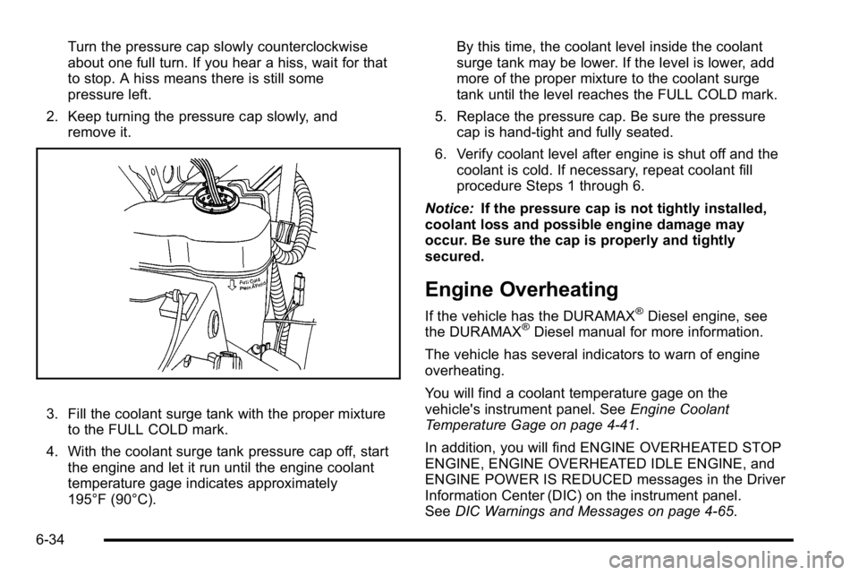
Turn the pressure cap slowly counterclockwise
about one full turn. If you hear a hiss, wait for that
to stop. A hiss means there is still some
pressure left.
2. Keep turning the pressure cap slowly, and remove it.
3. Fill the coolant surge tank with the proper mixtureto the FULL COLD mark.
4. With the coolant surge tank pressure cap off, start the engine and let it run until the engine coolant
temperature gage indicates approximately
195°F (90°C). By this time, the coolant level inside the coolant
surge tank may be lower. If the level is lower, add
more of the proper mixture to the coolant surge
tank until the level reaches the FULL COLD mark.
5. Replace the pressure cap. Be sure the pressure cap is hand-tight and fully seated.
6. Verify coolant level after engine is shut off and the coolant is cold. If necessary, repeat coolant fill
procedure Steps 1 through 6.
Notice: If the pressure cap is not tightly installed,
coolant loss and possible engine damage may
occur. Be sure the cap is properly and tightly
secured.
Engine Overheating
If the vehicle has the DURAMAX®Diesel engine, see
the DURAMAX®Diesel manual for more information.
The vehicle has several indicators to warn of engine
overheating.
You will find a coolant temperature gage on the
vehicle's instrument panel. See Engine Coolant
Temperature Gage on page 4‑41.
In addition, you will find ENGINE OVERHEATED STOP
ENGINE, ENGINE OVERHEATED IDLE ENGINE, and
ENGINE POWER IS REDUCED messages in the Driver
Information Center (DIC) on the instrument panel.
See DIC Warnings and Messages on page 4‑65.
6-34
Page 502 of 630
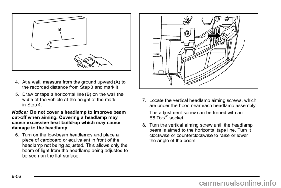
4. At a wall, measure from the ground upward (A) tothe recorded distance from Step 3 and mark it.
5. Draw or tape a horizontal line (B) on the wall the width of the vehicle at the height of the mark
in Step 4.
Notice: Do not cover a headlamp to improve beam
cut-off when aiming. Covering a headlamp may
cause excessive heat build-up which may cause
damage to the headlamp.
6. Turn on the low-beam headlamps and place a piece of cardboard or equivalent in front of the
headlamp not being adjusted. This allows only the
beam of light from the headlamp being adjusted to
be seen on the flat surface.
7. Locate the vertical headlamp aiming screws, whichare under the hood near each headlamp assembly.
The adjustment screw can be turned with an
E8 Torx
®socket.
8. Turn the vertical aiming screw until the headlamp beam is aimed to the horizontal tape line. Turn it
clockwise or counterclockwise to raise or lower
the angle of the beam.
6-56
Page 504 of 630
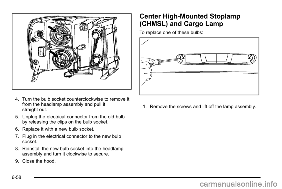
4. Turn the bulb socket counterclockwise to remove itfrom the headlamp assembly and pull it
straight out.
5. Unplug the electrical connector from the old bulb by releasing the clips on the bulb socket.
6. Replace it with a new bulb socket.
7. Plug in the electrical connector to the new bulb socket.
8. Reinstall the new bulb socket into the headlamp assembly and turn it clockwise to secure.
9. Close the hood.
Center High-Mounted Stoplamp
(CHMSL) and Cargo Lamp
To replace one of these bulbs:
1. Remove the screws and lift off the lamp assembly.
6-58
Page 505 of 630
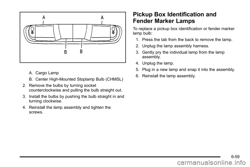
A. Cargo Lamp
B. Center High-Mounted Stoplamp Bulb (CHMSL)
2. Remove the bulbs by turning socket counterclockwise and pulling the bulb straight out.
3. Install the bulbs by pushing the bulb straight in and turning clockwise.
4. Reinstall the lamp assembly and tighten the screws.
Pickup Box Identification and
Fender Marker Lamps
To replace a pickup box identification or fender marker
lamp bulb:
1. Press the tab from the back to remove the lamp.
2. Unplug the lamp assembly harness.
3. Gently pry the individual lamp from the lamp assembly.
4. Unplug the lamp.
5. Plug in a new lamp and snap it into the assembly.
6. Reinstall the lamp assembly.
6-59
Page 506 of 630
Taillamps, Turn Signal, Stoplamps
and Back-up Lamps
To replace one of these bulbs:1. Open the tailgate. Tailgate
on page 3‑12for
more information.
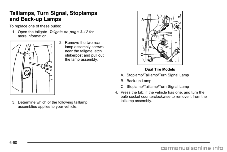
2. Remove the two rear lamp assembly screws
near the tailgate latch
strikerpost and pull out
the lamp assembly.
3. Determine which of the following taillamp assemblies applies to your vehicle.
Dual Tire Models
A. Stoplamp/Taillamp/Turn Signal Lamp
B. Back-up Lamp
C. Stoplamp/Taillamp/Turn Signal Lamp
4. Press the tab, if the vehicle has one, and turn the bulb socket counterclockwise to remove it from the
taillamp assembly.
6-60
Page 507 of 630
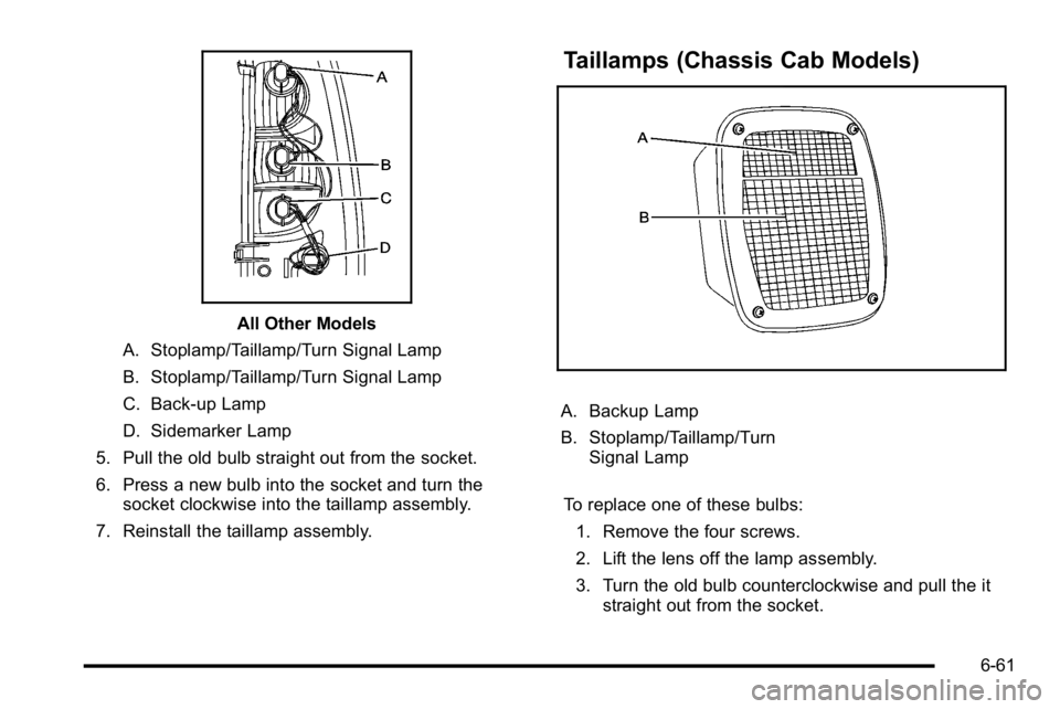
All Other Models
A. Stoplamp/Taillamp/Turn Signal Lamp
B. Stoplamp/Taillamp/Turn Signal Lamp
C. Back-up Lamp
D. Sidemarker Lamp
5. Pull the old bulb straight out from the socket.
6. Press a new bulb into the socket and turn the socket clockwise into the taillamp assembly.
7. Reinstall the taillamp assembly.
Taillamps (Chassis Cab Models)
A. Backup Lamp
B. Stoplamp/Taillamp/Turn Signal Lamp
To replace one of these bulbs: 1. Remove the four screws.
2. Lift the lens off the lamp assembly.
3. Turn the old bulb counterclockwise and pull the it straight out from the socket.
6-61
Page 508 of 630
4. Install a new bulb into the socket, turn it clockwise,and press it in until it is tight.
5. Reinstall the lens and the four screws.
License Plate Lamp
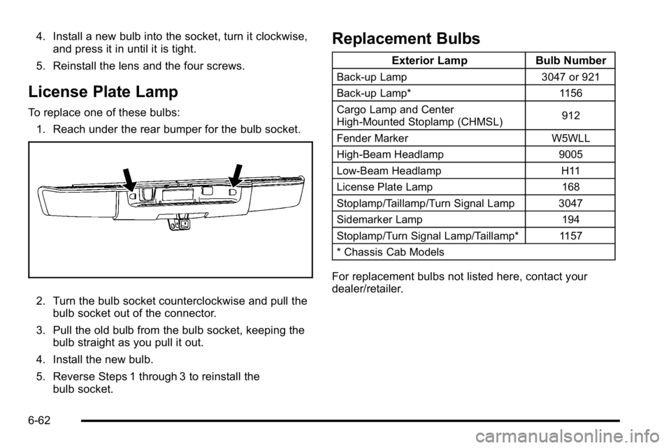
To replace one of these bulbs: 1. Reach under the rear bumper for the bulb socket.
2. Turn the bulb socket counterclockwise and pull the bulb socket out of the connector.
3. Pull the old bulb from the bulb socket, keeping the bulb straight as you pull it out.
4. Install the new bulb.
5. Reverse Steps 1 through 3 to reinstall the bulb socket.
Replacement Bulbs
Exterior Lamp Bulb Number
Back-up Lamp 3047 or 921
Back-up Lamp* 1156
Cargo Lamp and Center
High-Mounted Stoplamp (CHMSL) 912
Fender Marker W5WLL
High-Beam Headlamp 9005
Low-Beam Headlamp H11
License Plate Lamp 168
Stoplamp/Taillamp/Turn Signal Lamp 3047
Sidemarker Lamp 194
Stoplamp/Turn Signal Lamp/Taillamp* 1157
* Chassis Cab Models
For replacement bulbs not listed here, contact your
dealer/retailer.
6-62
Page 539 of 630
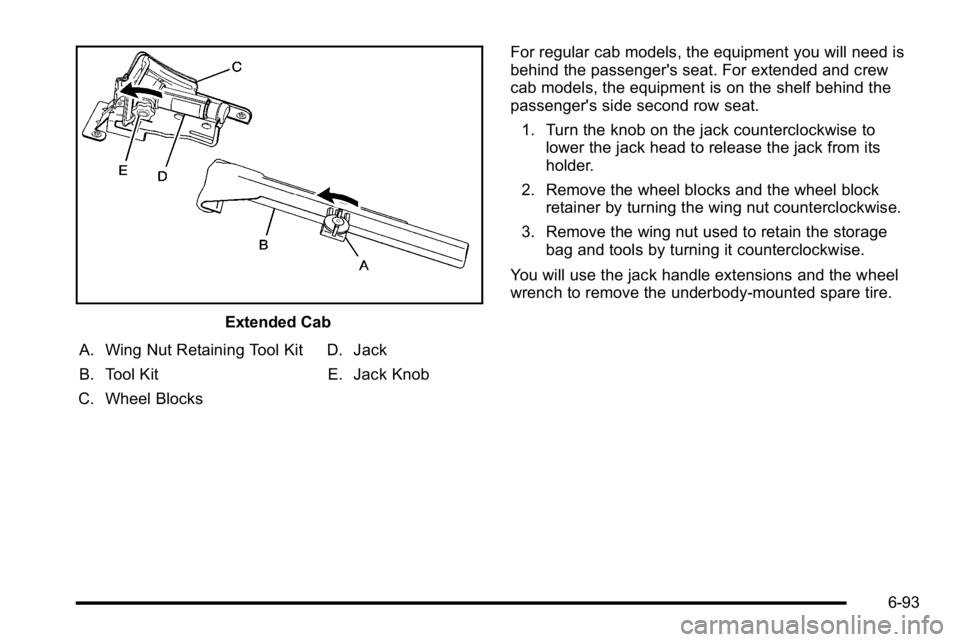
Extended Cab
A. Wing Nut Retaining Tool Kit
B. Tool Kit
C. Wheel Blocks D. Jack
E. Jack Knob For regular cab models, the equipment you will need is
behind the passenger's seat. For extended and crew
cab models, the equipment is on the shelf behind the
passenger's side second row seat.
1. Turn the knob on the jack counterclockwise to lower the jack head to release the jack from its
holder.
2. Remove the wheel blocks and the wheel block retainer by turning the wing nut counterclockwise.
3. Remove the wing nut used to retain the storage bag and tools by turning it counterclockwise.
You will use the jack handle extensions and the wheel
wrench to remove the underbody-mounted spare tire.
6-93
Page 541 of 630
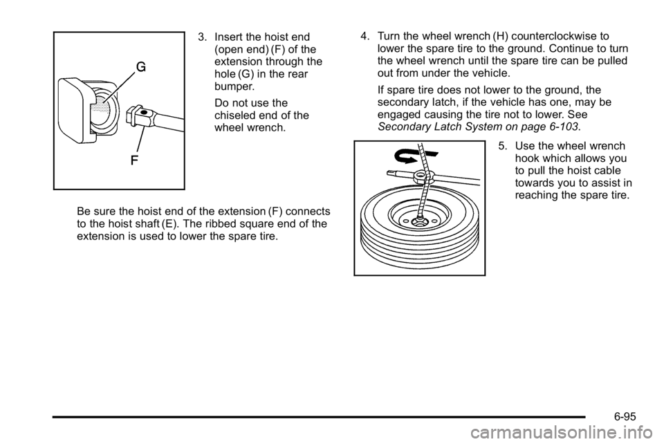
3. Insert the hoist end(open end) (F) of the
extension through the
hole (G) in the rear
bumper.
Do not use the
chiseled end of the
wheel wrench.
Be sure the hoist end of the extension (F) connects
to the hoist shaft (E). The ribbed square end of the
extension is used to lower the spare tire. 4. Turn the wheel wrench (H) counterclockwise to
lower the spare tire to the ground. Continue to turn
the wheel wrench until the spare tire can be pulled
out from under the vehicle.
If spare tire does not lower to the ground, the
secondary latch, if the vehicle has one, may be
engaged causing the tire not to lower. See
Secondary Latch System on page 6‑103.
5. Use the wheel wrench
hook which allows you
to pull the hoist cable
towards you to assist in
reaching the spare tire.
6-95