auxiliary battery GMC SIERRA 2010 Owner's Manual
[x] Cancel search | Manufacturer: GMC, Model Year: 2010, Model line: SIERRA, Model: GMC SIERRA 2010Pages: 630, PDF Size: 4.65 MB
Page 35 of 630
Rear Vision Camera (RVC)
The rear vision camera displays a view of the area
behind the vehicle when the vehicle is shifted into
R (Reverse) on the inside rear view mirror or the
navigation screen, if equipped.
To clean the camera lens, located in the bezel for the
tailgate handle, rinse it with water and wipe it with a
soft cloth.
For more information, seeRear Vision Camera (RVC)
on page 3‑63.
Ultrasonic Parking Assist
This feature uses sensors on the rear bumper to detect
objects while parking the vehicle. URPA comes on
automatically when the shift lever is moved into
R (Reverse) and operates at speeds less than 8 km/h
(5 mph). URPA uses audio beeps to provide distance
and system information.
Keep the sensors on the vehicle's rear bumper clean to
ensure proper operation.
The system can be disabled by pressing the rear park
aid disable button located next to the radio.
SeeUltrasonic Rear Parking Assist (URPA)
on
page 3‑60for more information.
Power Outlets
Accessory power outlets can be used to connect
auxiliary electrical equipment, such as a cellular
telephone.
The vehicle may have two accessory power outlets
located below the climate control system, or may have
one accessory power outlet and one cigarette lighter.
The cigarette lighter is designed to fit only in the
receptacle closest to the driver.
There may be another accessory power outlet in the
rear cargo area. If the vehicle has a floor console, there
is an accessory power outlet inside the storage bin and
one on the rear of the floor console.
The accessory power outlets are powered, even when
the ignition is in LOCK/OFF. Continuing to use power
outlets while the ignition is in LOCK/OFF may cause the
vehicle's battery to run down.
See Accessory Power Outlet(s) on page 4‑17.
1-29
Page 219 of 630
Section 4 Instrument Panel
Instrument Panel Overview. . . . . . . . . . . . . . . . . . . . . . . .4-3
Hazard Warning Flashers . . . . . . . . . . . . . . . . . . . . . . . 4-3
Horn . . . . . . . . . . . . . . . . . . . . . . . . . . . . . . . . . . . . . . . . . . . . 4-3
Tilt Wheel . . . . . . . . . . . . . . . . . . . . . . . . . . . . . . . . . . . . . . . 4-3
Turn Signal/Multifunction Lever . . . . . . . . . . . . . . . . . . 4-4
Turn and Lane-Change Signals . . . . . . . . . . . . . . . . . 4-4
Headlamp High/Low-Beam Changer . . . . . . . . . . . . 4-5
Flash-to-Pass . . . . . . . . . . . . . . . . . . . . . . . . . . . . . . . . . . . 4-5
Windshield Wipers . . . . . . . . . . . . . . . . . . . . . . . . . . . . . . 4-6
Windshield Washer . . . . . . . . . . . . . . . . . . . . . . . . . . . . . 4-6
Cruise Control . . . . . . . . . . . . . . . . . . . . . . . . . . . . . . . . . . 4-7
Exterior Lamps . . . . . . . . . . . . . . . . . . . . . . . . . . . . . . . . 4-10
Headlamps on Reminder . . . . . . . . . . . . . . . . . . . . . . . 4-11
Daytime Running Lamps (DRL) . . . . . . . . . . . . . . . . 4-12
Automatic Headlamp System . . . . . . . . . . . . . . . . . . 4-12
Puddle Lamps . . . . . . . . . . . . . . . . . . . . . . . . . . . . . . . . . 4-13
Fog Lamps . . . . . . . . . . . . . . . . . . . . . . . . . . . . . . . . . . . . 4-13
Auxiliary Roof-Mounted Lamp . . . . . . . . . . . . . . . . . 4-14
Instrument Panel Brightness . . . . . . . . . . . . . . . . . . . 4-14
Dome Lamps . . . . . . . . . . . . . . . . . . . . . . . . . . . . . . . . . . 4-14
Dome Lamp Override . . . . . . . . . . . . . . . . . . . . . . . . . . 4-15
Entry Lighting . . . . . . . . . . . . . . . . . . . . . . . . . . . . . . . . . . 4-15
Exit Lighting . . . . . . . . . . . . . . . . . . . . . . . . . . . . . . . . . . . 4-15
Reading Lamps . . . . . . . . . . . . . . . . . . . . . . . . . . . . . . . . 4-15
Cargo Lamp . . . . . . . . . . . . . . . . . . . . . . . . . . . . . . . . . . . 4-15 Electric Power Management . . . . . . . . . . . . . . . . . . . 4-16
Battery Run-Down Protection . . . . . . . . . . . . . . . . . . 4-16
Accessory Power Outlet(s) . . . . . . . . . . . . . . . . . . . . . 4-17
Ashtray(s) and Cigarette Lighter . . . . . . . . . . . . . . . 4-18
Climate Controls . . . . . . . . . . . . . . . . . . . . . . . . . . . . . . . . . . 4-18
Climate Control System (With Heater Only) . . . . 4-18
Climate Control System (With Air Conditioning) . . . . . . . . . . . . . . . . . . . . . . . 4-20
Dual Automatic Climate Control System . . . . . . . 4-22
Outlet Adjustment . . . . . . . . . . . . . . . . . . . . . . . . . . . . . . 4-29
Warning Lights, Gages, and Indicators . . . . . . . . . .4-29
Instrument Panel Cluster . . . . . . . . . . . . . . . . . . . . . . . 4-30
Speedometer and Odometer . . . . . . . . . . . . . . . . . . . 4-31
Trip Odometer . . . . . . . . . . . . . . . . . . . . . . . . . . . . . . . . . 4-31
Tachometer . . . . . . . . . . . . . . . . . . . . . . . . . . . . . . . . . . . . 4-31
Safety Belt Reminders . . . . . . . . . . . . . . . . . . . . . . . . . 4-32
Airbag Readiness Light . . . . . . . . . . . . . . . . . . . . . . . . 4-33
Airbag Off Light . . . . . . . . . . . . . . . . . . . . . . . . . . . . . . . . 4-34
Passenger Airbag Status Indicator . . . . . . . . . . . . . 4-36
Charging System Light . . . . . . . . . . . . . . . . . . . . . . . . 4-37
Voltmeter Gage . . . . . . . . . . . . . . . . . . . . . . . . . . . . . . . . 4-38
Brake System Warning Light . . . . . . . . . . . . . . . . . . . 4-39
Antilock Brake System (ABS) Warning Light . . . 4-40
StabiliTrak
®Indicator Light . . . . . . . . . . . . . . . . . . . . . 4-41
Engine Coolant Temperature Gage . . . . . . . . . . . . 4-41
4-1
Page 235 of 630
Accessory Power Outlet(s)
Accessory power outlets can be used to connect
auxiliary electrical equipment, such as a cellular
telephone.
The vehicle may have two accessory power outlets
located below the climate control system, or may have
one accessory power outlet and one cigarette lighter.
The cigarette lighter is designed to fit only in the
receptacle closest to the driver.
There may be another accessory power outlet in the
rear cargo area. If the vehicle has a floor console, there
is an accessory power outlet inside the storage bin and
one on the rear of the floor console.
To use an accessory power outlet, remove the
protective cap. When not in use, always cover the
accessory power outlet with the protective cap.
Notice:Leaving electrical equipment plugged in for
an extended period of time while the vehicle is off
will drain the battery. Power is always supplied to
the outlets. Always unplug electrical equipment
when not in use and do not plug in equipment that
exceeds the maximum 20 ampere rating. Certain power accessory plugs may not be compatible
to the accessory power outlet and could result in blown
vehicle or adapter fuses. If you experience a problem,
see your dealer/retailer for additional information on the
accessory power plugs.
The accessory power outlets are powered, even when
the ignition is in LOCK/OFF. Continuing to use power
outlets while the ignition is in LOCK/OFF may cause the
vehicle's battery to run down.
Notice:
Adding any electrical equipment to the
vehicle can damage it or keep other components
from working as they should. The repairs would not
be covered by the vehicle warranty. Do not use
equipment exceeding maximum amperage rating of
20 amperes. Check with your dealer/retailer before
adding electrical equipment.
When adding electrical equipment, be sure to follow the
proper installation instructions included with the
equipment.
Notice: Improper use of the power outlet can cause
damage not covered by the vehicle warranty. Do not
hang any type of accessory or accessory bracket
from the plug because the power outlets are
designed for accessory power plugs only.
4-17
Page 324 of 630
Drivers are encouraged to set up any auxiliary device
while the vehicle is in P (Park). SeeDefensive Driving
on page 5‑2for more information on driver distraction.
To use a portable audio player, connect a 3.5 mm
(1/8 in) cable to the radio's front auxiliary input jack.
When a device is connected, press the radio CD/AUX
button to begin playing audio from the device over the
vehicle speakers.
For optimal sound quality, increase the portable audio
device's volume to the loudest level.
It is always best to power the portable audio device
through its own battery while playing.
O(Power/Volume): Turn clockwise or
counterclockwise to increase or decrease the
volume of the portable player. Additional volume
adjustments might have to be made from the portable
device if the volume is not loud or soft enough.
BAND : Press to listen to the radio when a portable
audio device is playing. The portable audio device
continues playing.
CD/AUX (CD/Auxiliary) : Press to play a CD when a
portable audio device is playing. Press again and the
system begins playing audio from the connected
portable audio player. If a portable audio player is not
connected, “No Input Device Found” displays.DVD/CD AUX (CD/Auxiliary) :
Press to cycle thro
ugh DVD, CD, or Auxiliary when listening to the radio.
The DVD/CD text tab and a message showing track or
chapter number displays when a disc is in either slot.
Press again and the system automatically searches for
an auxiliary input device, such as a portable audio
player. If a portable audio player is not connected,
“No Aux Input Device” displays. If a disc is in both the
DVD slot and the CD slot the DVD/CD AUX button
cycles between the two sources and not indicate
“No Aux Input Device”. If a front auxiliary device is
connected, the DVD/CD AUX button cycles through
all available options, such as: DVD slot, CD slot,
Front Auxiliary, and Rear Auxiliary (if available).
See “Using the Auxiliary Input Jack(s)” later in this
section, or “Audio/Video (A/V) Jacks” under,Rear Seat
Entertainment (RSE) System
on page 4‑134for more
information.
Using the USB Port
Radios with a USB port can control a USB storage
device or an iPod®using the radio buttons and knobs.
See Using an MP3 (Radios with CD)on page 4‑107or
Using an MP3 (Radios with CD and DVD)on
page 4‑114for information about how to connect and
control a USB storage device or an iPod.
4-106
Page 329 of 630
Connecting a USB Storage Device
or iPod®
The USB Port can be used to control an iPod or a
USB storage device.
To connect a USB storage device, connect the device to
the USB port located in the center console or on the
instrument panel.
To connect an iPod, connect one end of the USB cable
that came with the iPod to the iPod’s dock connector
and connect the other end to the USB port located in
the center console or on the instrument panel. If the
vehicle is on and the USB connection works, “OK to
disconnect” and a GM logo may appear on the iPod and
iPod appears on the radio display. The iPod music
appears on the radio’s display and begins playing.
The iPod charges while it is connected to the vehicle if
the vehicle is in the ACC/ACCESSORY or ON/RUN
position. When the vehicle is turned off, the iPod
automatically powers off and will not charge or draw
power from the vehicle's battery.
If you have an older iPod model that is not supported, it
can still be used by connecting it to the Auxiliary Input
Jack using a standard 3.5 mm (1/8 in) stereo cable.
See “Using the Auxiliary Input Jack” earlier for more
information.
Using the Radio to Control a USB
Storage Device or iPod
The radio can control a USB storage device or an
iPod using the radio buttons and knobs and display
song information on the radio’s display.
f(Tune): Turn to select files.
©SEEK:Press to go to the start of the track, if more
than ten seconds have played. Press and hold or press
multiple times to continue moving backward through
tracks.
¨SEEK: Press to go to the next track. Press and hold
or press multiple times to continue moving forward
through tracks.
sREV (Reverse): Press and hold to reverse
playback quickly. Sound is heard at a reduced volume.
Release
sREV to resume playing. The elapsed time
of the file displays.
\FWD (Fast Forward): Press and hold to advance
playback quickly. Sound is heard at a reduced volume.
Release
\FWD to resume playing. The elapsed time
of the file displays.
4(Information): Press to display additional information
about the selected track.
4-111
Page 336 of 630
When the scan is finished, the disc begins playing files
in order by artist. The current artist playing is shown on
the second line of the display. Once all songs by that
artist are played, the player moves to the next artist in
alphabetical order and begins playing files by that artist.
To listen to files by another artist, press the softkey
located below either arrow tab. The disc goes to the
next or previous artist in alphabetical order. Continue
pressing either softkey below the arrow tab until the
artist displays.
To change from playback by artist to playback by
album:1. Press the softkey located below the Sort By tab.
2. Press one of the softkeys below the album tab from the sort screen.
3. Press the softkey below the back tab to return to the main music navigator screen.
The album name displays on the second line between
the arrows and songs from the current album begin to
play. Once all songs from that album have played, the
player moves to the next album in alphabetical order on
the CD and begins playing MP3 files from that album.
To exit music navigator mode, press the softkey below
the Back tab to return to normal MP3 playback.Connecting a USB Storage Device
or iPod®
The USB Port can be used to control an iPod or a
USB storage device.
To connect a USB storage device, connect the device to
the USB port located in the center console or on the
instrument panel.
To connect an iPod, connect one end of the USB cable
that came with the iPod to the iPod’ s dock connector
and connect the other end to the USB port located in
the center console or on the instrument panel. If the
vehicle is on and the USB connection works, “OK to
disconnect” and a GM logo may appear on the iPod and
iPod appears on the radio display. The iPod music
appears on the radio’s display and begins playing.
The iPod charges while it is connected to the vehicle if
the vehicle is in the ACC/ACCESSORY or ON/RUN
position. When the vehicle is turned off, the iPod
automatically powers off and will not charge or draw
power from the vehicle's battery.
If you have an older iPod model that is not supported, it
can still be used by connecting it to the Auxiliary Input
Jack using a standard 3.5 mm (1/8 in) stereo cable.
See “Using the Auxiliary Input Jack” earlier for more
information.
4-118
Page 353 of 630
Headphones
The RSE includes two 2-channel wireless headphones
that are dedicated to this system. Channel 1 is
dedicated to the video screen, while Channel 2 is
dedicated to RSA selections. These headphones can
used to listen to the radio, CDs, DVDs, MP3s, DVDAs,
any auxiliary source connected to A/V jacks, or the
auxiliary input jack, if the vehicle has this feature.
The wireless headphones have an On/Off button,
channel 1/2 switch, and a volume control.
Push the power button to turn on the headphones.
An indicator light located on the headphones comes on.
If the light comes on but, there is intermittent sound
and/or static on the headphones, or if the indicator light
does not come on, the batteries might need to be
replaced. See“Battery Replacement” later in this
section for more information. Switch the headphones
to Off when not in use.
Infrared transmitters are located at the rear of the
overhead console. The headphones shut off
automatically to save the battery power if the RSE
system and RSA are shut off or if the headphones are
out of range of the transmitters for more than
three minutes. If you move too far forward or step out of
the vehicle, the headphones lose the audio signal.
The headphones may automatically turn off after
four hours of continuous use. To adjust the volume on the headphones, use the
volume control located on the right side.
For optimal audio performance, the headphones must
be worn correctly. Headphones should be worn with
headband over the top of the head for best audio
reception. The symbol L (Left) appears on the upper left
side, above the ear pad and should be positioned on
the left ear. The symbol R (Right) appears on the upper
right side, above the ear pad and should be positioned
on the right ear.
Notice:
Do not store the headphones in heat or
direct sunlight. This could damage the headphones
and repairs will not be covered by the warranty.
Storage in extreme cold can weaken the batteries.
Keep the headphones stored in a cool, dry place.
If the foam ear pads attached to the headphones
become worn or damaged, the pads can be replaced
separately from the headphone set. Refer to your
dealer/retailer for more information.
4-135
Page 354 of 630
Battery Replacement
To change the batteries on the headphones, do the
following:1. Turn the screw to loosen the battery door located on the left side of the headphones. Slide the
battery door open.
2. Replace the two batteries in the compartment. Make sure that they are installed correctly, using
the diagram on the inside of the battery
compartment.
3. Replace the battery door and tighten the door screw.
If the headphones are to be stored for a long period
of time, remove the batteries and keep them in a cool,
dry place.
Audio/Video (A/V) Jacks
The A/V jacks, located on the rear of the floor console,
allow audio or video signals to be connected from an
auxiliary device such as a camcorder or a video game
unit to the RSE system. Adapter connectors or cables
(not included) may be required to connect the auxiliary
device to the A/V jacks. Refer to the manufacturer ’s
instructions for proper usage.
The A/V jacks are color coded to match typical home
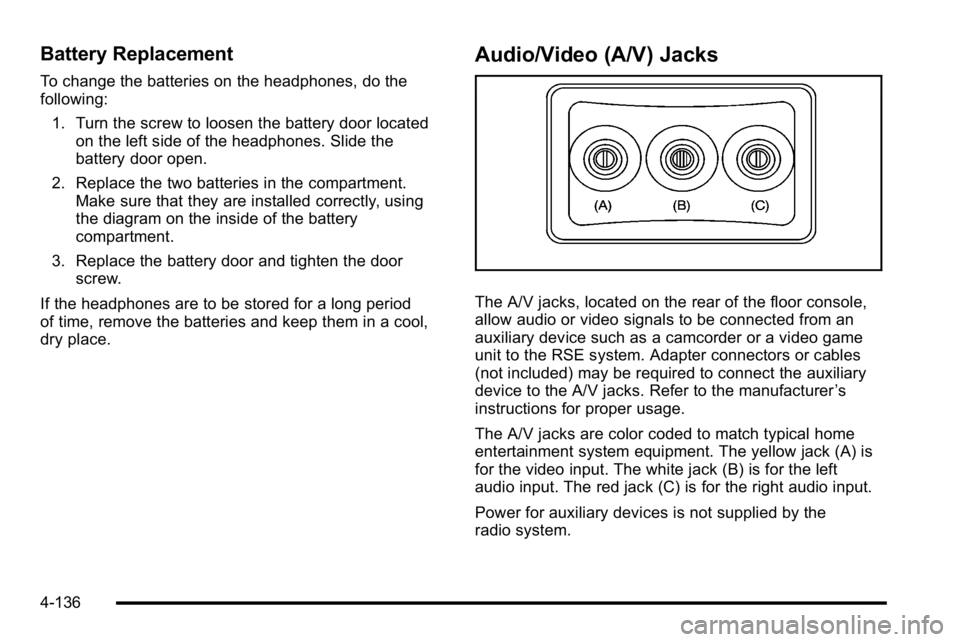
entertainment system equipment. The yellow jack (A) is
for the video input. The white jack (B) is for the left
audio input. The red jack (C) is for the right audio input.
Power for auxiliary devices is not supplied by the
radio system.
4-136
Page 359 of 630
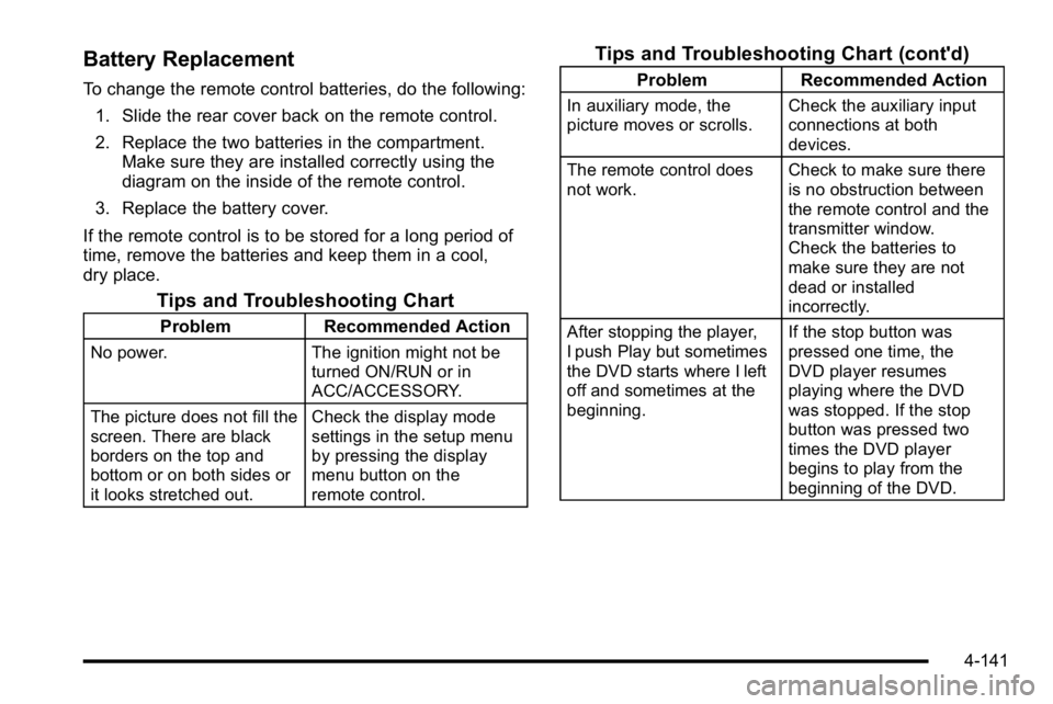
Battery Replacement
To change the remote control batteries, do the following:1. Slide the rear cover back on the remote control.
2. Replace the two batteries in the compartment. Make sure they are installed correctly using the
diagram on the inside of the remote control.
3. Replace the battery cover.
If the remote control is to be stored for a long period of
time, remove the batteries and keep them in a cool,
dry place.
Tips and Troubleshooting Chart
Problem Recommended Action
No power. The ignition might not be
turned ON/RUN or in
ACC/ACCESSORY.
The picture does not fill the
screen. There are black
borders on the top and
bottom or on both sides or
it looks stretched out. Check the display mode
settings in the setup menu
by pressing the display
menu button on the
remote control.
Tips and Troubleshooting Chart (cont'd)
Problem
Recommended Action
In auxiliary mode, the
picture moves or scrolls. Check the auxiliary input
connections at both
devices.
The remote control does
not work. Check to make sure there
is no obstruction between
the remote control and the
transmitter window.
Check the batteries to
make sure they are not
dead or installed
incorrectly.
After stopping the player,
I push Play but sometimes
the DVD starts where I left
off and sometimes at the
beginning. If the stop button was
pressed one time, the
DVD player resumes
playing where the DVD
was stopped. If the stop
button was pressed two
times the DVD player
begins to play from the
beginning of the DVD.
4-141
Page 443 of 630
*The fuses for these two circuits are installed in the
underhood electrical center, but the wires are not
connected. They should be connected by your dealer/
retailer or a qualified service center. The fuse and wire
for the ITBC is factory installed and connected if the
vehicle is equipped with an ITBC. The fuse for the
battery feed is not required if the vehicle has an
auxiliary battery. If the vehicle does not have an
auxiliary battery, have your dealer/retailer or authorized
service center install the required fuse.
If charging a remote (non-vehicle) battery, press the
Tow/Haul mode button, if equipped, located at the end
of the shift lever. This will boost the vehicle system
voltage and properly charge the battery. If the trailer is
too light for Tow/Haul mode, or the vehicle is not
equipped with Tow/Haul, turn on the headlamps as a
second way to boost the vehicle system and charge
the battery.Camper/Fifth-Wheel Trailer Wiring Package
The seven-wire camper harness is located under the
front edge of the pickup box on the drivers side of the
vehicle, attached to the frame bracket. A connector
must be added to the wiring harness which connects to
the camper.
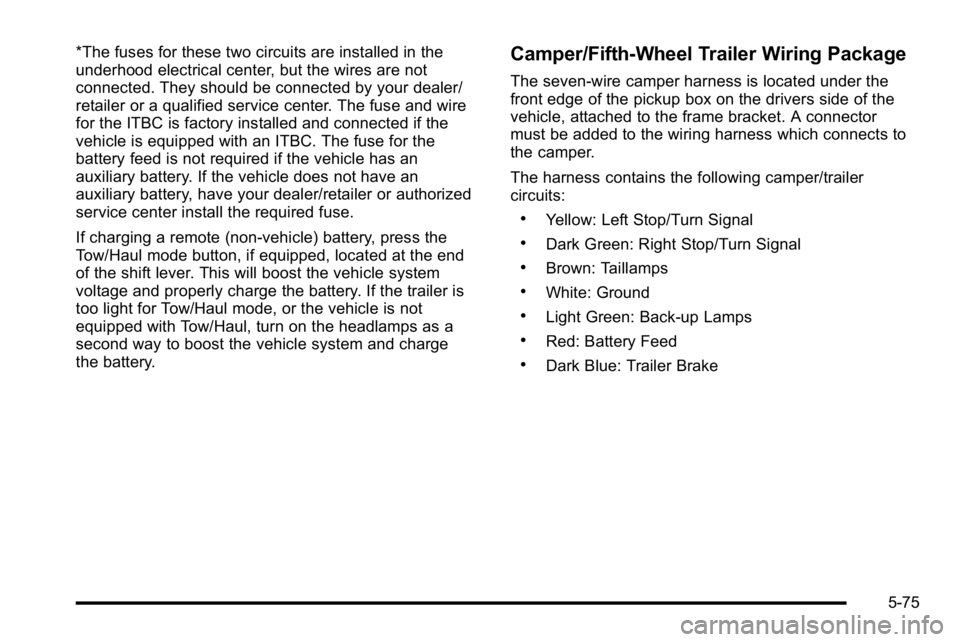
The harness contains the following camper/trailer
circuits:
.Yellow: Left Stop/Turn Signal
.Dark Green: Right Stop/Turn Signal
.Brown: Taillamps
.White: Ground
.Light Green: Back-up Lamps
.Red: Battery Feed
.Dark Blue: Trailer Brake
5-75