instrument panel GMC SIERRA 2021 Get To Know Guide
[x] Cancel search | Manufacturer: GMC, Model Year: 2021, Model line: SIERRA, Model: GMC SIERRA 2021Pages: 20, PDF Size: 2.48 MB
Page 2 of 20
2
INSTRUMENT PANEL
Engine
Start/Stop Button
F
Cruise Control/ Forward Collision AlertF/Heated
Steering WheelF
Buttons
Electric Parking Brake
Switch
Power
Mirror
F/
Window Buttons Driver
Information Center
Controls
F/Voice
Recognition Buttons
Audio Volume
Control
(on back
of steering wheel)
Steering
Wheel
Adjustment Lever
(on steering column)
Audio Next/
Previous Favorite Station Controls (on back of
steering wheel)
Exterior/
Instrument
Panel/Cargo
Lamp Controls 4WD
Controls
F/
Traction Select Controls Turn Signal/
Windshield
Wipers Lever Range +/-
Gear Selection Buttons
(on shift lever)
Driver
Information Center
HUD ControlsF
(behind
steering wheel)
Low Fuel
Traction Control Off
Brake System
Cruise Control
StabiliTrak Active
StabiliTrak Off
Forward Collision Alert
Security
PARK Electric Parking Brake
Electric Parking Brake Service
Lights On Reminder
Airbag Readiness
Engine Oil Pressure
Check Engine
Lane Keep Assist
Symbols
Gasoline model shown
Page 6 of 20
6
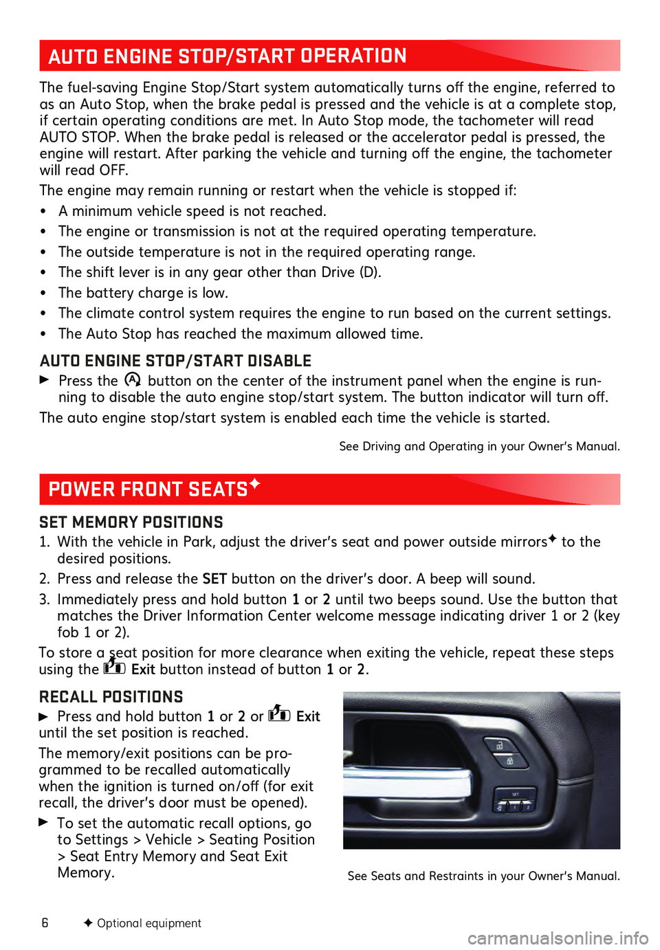
SET MEMORY POSITIONS
1. With the vehicle in Park, adjust the driver’s seat and power outside mirrorsF to the desired positions.
2. Press and release the SET button on the driver’s door. A beep will sound.
3. Immediately pres s and hold button 1 or 2 until two beeps sound. Use the button that
matches the Driver Information Center welcome message indicating driver 1 or 2 (key
fob 1 or 2).
To store a seat position for more clearance when exiting the vehicle, repeat these steps
using the
Exit button instead of button 1 or 2.
RECALL POSITIONS
Press and hold button 1 or 2 or Exit
until the set position is reached.
The memory/exit positions can be pro -
grammed to be recalled automatically
when the ignition is turned on/off (for exit
recall, the driver’s door must be opened).
To set the automatic recall options, go
to Settings > Vehicle > Seating Position
> Seat Entry Memory and Seat Exit
Memory.
POWER FRONT SEATSF
F Optional equipment
AUTO ENGINE STOP/START OPERATION
The fuel-saving Engine Stop/Start system automatically turns off the engine, referred to
as an Auto Stop, when the brake pedal is pressed and the vehicle is at a complete stop,
if certain operating conditions are met. In Auto Stop mode, the tachometer will read
AUTO STOP. When the brake pedal is released or the accelerator pedal is pressed, the
engine will restart. After parking the vehicle and turning off the engine, the tachometer
will read OFF.
The engine may remain running or restart when the vehicle is stopped if:
• A minimu m vehicle speed is not reached.
• The engine or transmiss ion is not at the required operating temperature.
• The outside temperature is not in the required operating range.
• The shift lever is in any gear other than Drive (D).
• The battery charge is low.
• The climate control system requires the engine to run based on the current settings.
• The Auto Stop has reach ed the maximum allowed time.
AUTO ENGINE STOP/START DISABLE
Press the �$ button on the center of the instrument panel when the engine is run -
ning to disable the auto engine stop/start system. The button indicator will turn off.
The auto engine stop/start system is enabled each time the vehicle is started.
See Driving and Operating in your Owner’s Manual.
See Seats and Restraints in your Owner’s Manual.
Page 7 of 20
7F Optional equipment
DRIVER INFORMATION CENTER
MULTICOLOR HEAD-UP DISPLAYF
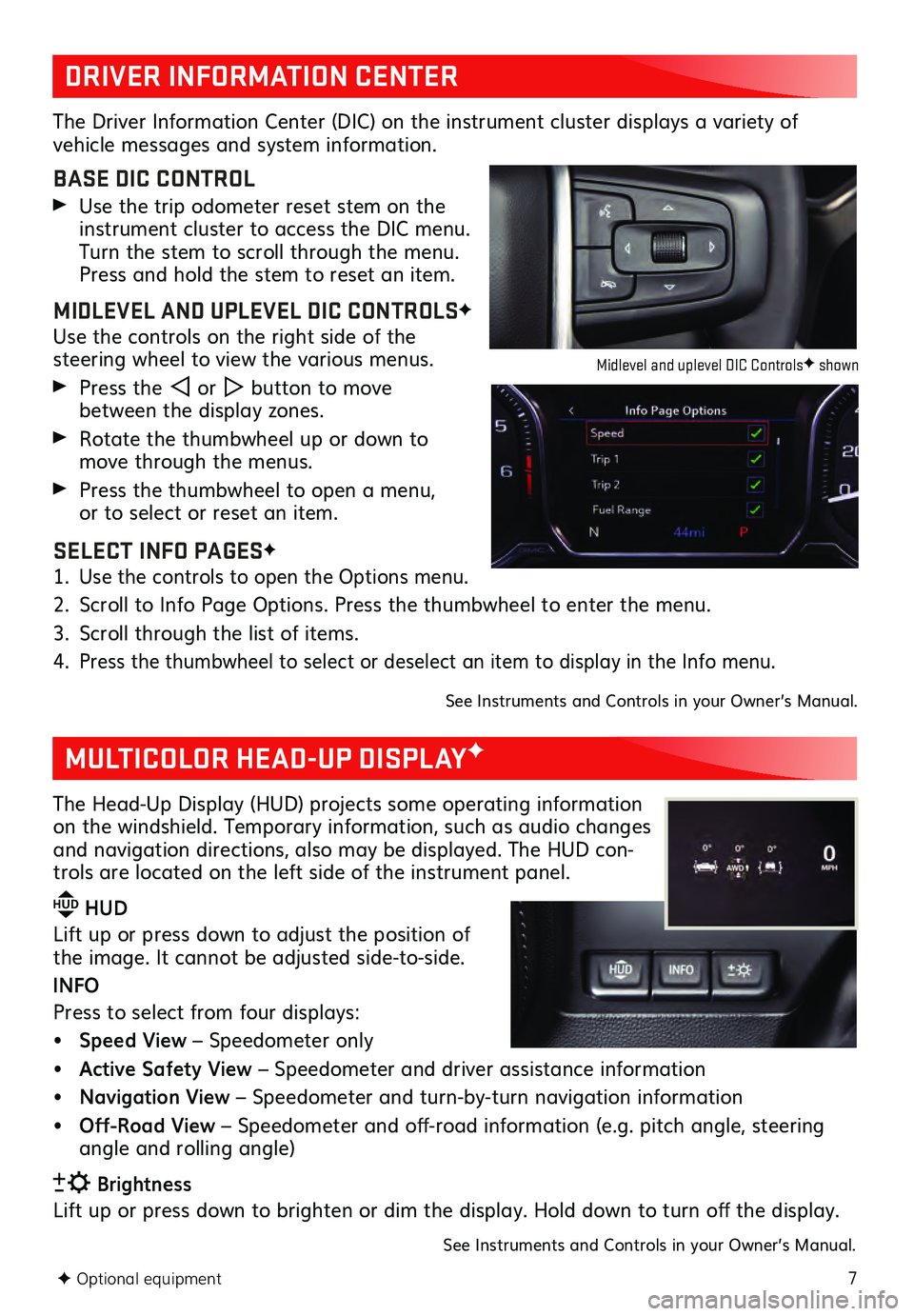
The Driver Information Center (DIC) on the instrument cluster displays a variety of vehicle messages and system information.
BASE DIC CONTROL
Use the trip odometer reset stem on the instrument cluster to access the DIC menu.
Turn the stem to scroll through the menu.
Press and hold the stem to reset an item.
MIDLEVEL AND UPLEVEL DIC CONTROLSF
Use the controls on the right side of the steering wheel to view the various menus.
Press the or button to move
between the display zones.
Rotate the thumbwheel up or down to move through the menus.
Press the thumbwheel to open a menu, or to select or reset an item.
SELECT INFO PAGESF
1. Use the controls to open the Options menu.
2. Scroll to Info Page Options. Press the thumbwheel to enter the menu.
3. Scroll through the list of items.
4. Press the thumbwheel to select or deselect an item to display in the Info menu.
See Instruments and Controls in your Owner’s Manual.
The Head-Up Display (HUD) projects some operating information
on the windshield. Temporary information, such as audio changes
and navigation directions, also may be displayed. The HUD con-
trols are located on the left side of the instrument panel.
HUD HUD
Lift up or press down to adjust the position of
the image. It ca nnot be adjusted side-to-side.
INFO
Press to select from four displays:
• Speed View – Speedometer only
• Active Safety View – Speedometer and driver assistance information
• Navigation View – Speedometer and turn-by-turn navigation information
• Off-Road View – Speedometer and off-road information (e.g. pitch angle, steering
angle and rolling angle)
Brightness
Lift up or press down to brighten or dim the display. Hold down to turn off the display.
See Instruments and Controls in your Owner’s Manual.
Midlevel and uplevel DIC ControlsF shown
Page 12 of 20
12F Optional equipment
LIGHTING
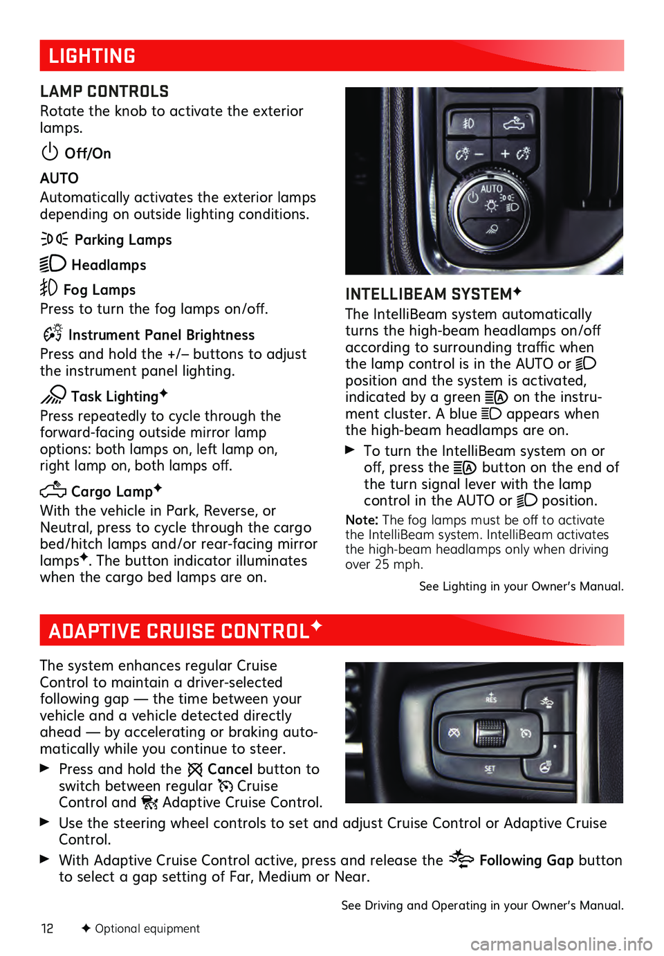
LAMP CONTROLS
Rotate the knob to activate the exterior
lamps.
Off/On
AUTO
Automatically activates the exterior lamps
depending on outside lighting conditions.
Parking Lamps
Headlamps
Fog Lamps
Press to turn the fog lamps on/off.
Instrument Panel Brightness
Press and hold the +/– buttons to adjust
the instrument panel lighting.
Task LightingF
Press repeatedly to cycle through the forward-facing outside mirror lamp options: both lamps on, left lamp on, right lamp on, both lamps off.
Cargo LampF
With the vehicle in Park, Reverse, or
Neutral, press to cycle through the cargo
bed/hitch lamps and/or rear-facing mirror
lamps
F. The button indicator illuminates
when the cargo bed lamps are on.
INTELLIBEAM SYSTEMF
The IntelliBeam system automatically
turns the high-beam headlamps on/off
according to surrounding traffic when
the lamp control is in the AUTO or
position and the system is activated, indicated by a green on the instru -
ment cluster. A blue appears when
the high-beam headlamps are on.
To turn the IntelliBeam s ystem on or off, press the button on the end of
the turn signal lever with the lamp
control in the AUTO or
position.
Note: The fog lamps must be off to activate
the IntelliBeam system. IntelliBeam activates
the high-beam headlamps only when driving
over 25 mph.
See Lighting in your Owner’s Manual.
ADAPTIVE CRUISE CONTROLF
The system enhances regular Cruise
Control to maintain a driver-selected
following gap — the time between your vehicle and a vehicle detected directly
ahead — by accelerating or braking auto -
matically while you continue to steer.
Press and hold the Cancel button to
switch between regular Cruise Control and Adaptive Cruise Control.
Use the steering wheel controls to set and adjust Cruise Control or Adaptive Cruise Control.
With Adaptive Cruise Control active, press and release the Following Gap button
to select a gap setting of Far, Medium or Near.
See Driving and Operating in your Owner’s Manual.
Page 13 of 20
13
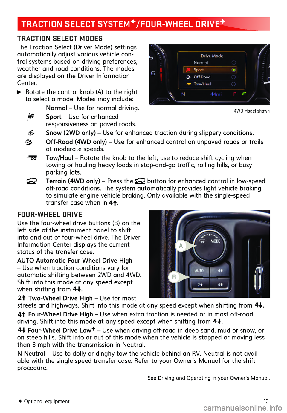
TRACTION SELECT MODES
The Traction Select (Driver Mode) settings automatically adjust various vehicle con-
trol systems based on driving preferences,
weather and road conditions. The modes
are displayed on the Driver Information
Center.
Rotate the control knob (A) to the right to select a mode. Modes may include:
Normal – Use for normal driving.
Sport – Use for enhanced responsiveness on paved roads.
Snow (2WD only) – Use for enhanced traction during slippery conditions.
Off-Road (4WD only) – Use for enhanced control on unpaved roads or trails at moderate speeds.
Tow/Haul – Rotate the knob to the left; use to reduce shift cycling when towing or hauling heavy loads in stop-and-go traffic, rolling hills, or busy parking lots.
Terrain (4WD only) – Press the button for enhanced control in low-speed off-road conditions. The system automatically provides light vehicle braking to simulate engine vehicle braking. Only available with the single-speed transfer case when in4
4
2
.
FOUR-WHEEL DRIVE
Use the four-wheel drive buttons (B) on the
left side of the instrument panel to shift
into and out of four-wheel drive. The Driver
Informa tion Center dis plays the current status of the transfer case.
AUTO Automatic Four-Wheel Drive High
– Use when traction conditions vary for
automatic shifting between 2WD and 4WD.
Shift into this mode at any speed except
when shifting from4
4
2
.
44
2
Two-Wheel Drive High – Use for most
streets and highways. Shift into this mode at any speed except when shifting from
4
4
2
.
4
4
2
Four-Wheel Drive High – Use when extra traction is needed or in most off-road driving. Shift into this mode at any speed except when shifting from
44
2
.
44
2
Four-Wheel Drive LowF – Use when driving off-road in deep sand, mud or snow, or
on steep hills. Shift into or out of this mode when the vehicle is stopped or moving less
than 3 mph with the transmission in Neutral.
N Neutral – Use to dolly or dinghy tow the vehicle behind an RV. Neutral is not avail -
able with the single speed transfer case. Refer to your Owner’s Manual for the shift procedure.
See Driving and Operating in your Owner’s Manual.
F Optional equipment
TRACTION SELECT SYSTEMF/FOUR-WHEEL DRIVEF
4WD Model shown
B
A
Page 15 of 20
15F Optional equipment
DRIVER ASSISTANCE SYSTEMSF
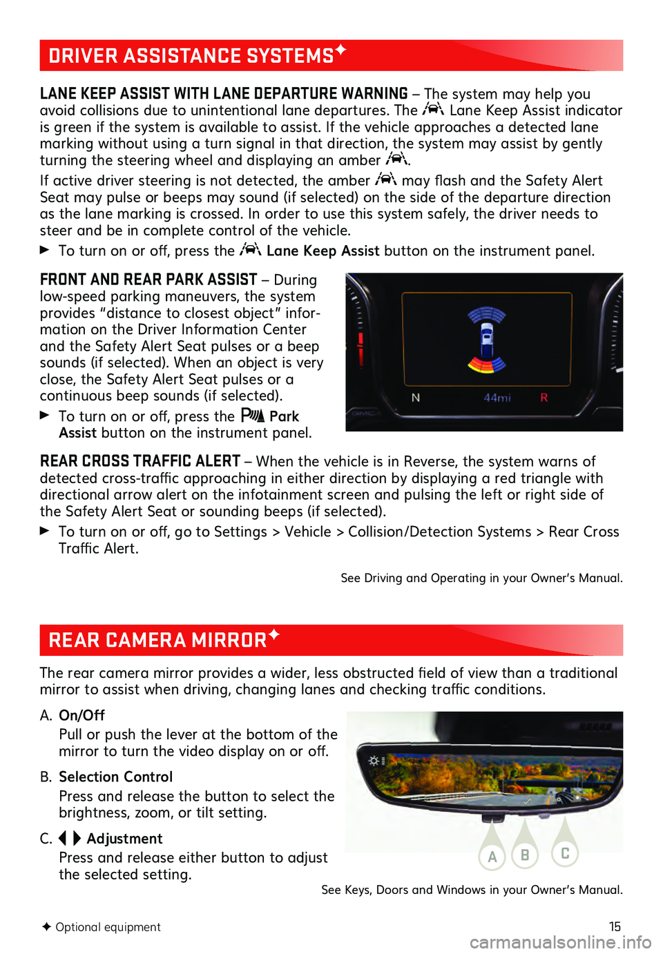
LANE KEEP ASSIST WITH LANE DEPARTURE WARNING – The system may help you
avoid collisions due to unintentional lane departures. The
Lane Keep Assist indicator
is green if the system is available to assist. If the vehicle approaches a detected lane
marking without using a turn signal in that direction, the system may assist by gently
turning the steering wheel and displaying an amber
.
If active driver steering is not detected, the amber may flash and the Safety Alert
Seat may pulse or beeps may sound (if selected) on the side of the departure direction
as the lane marking is crossed. In order to use this system safely, the driver needs to
steer and be in complete control of the vehicle.
To turn on or off, press the Lane Keep Assist button on the instrument panel.
FRONT AND REAR PARK ASSIST – During
low-speed parking maneuvers, the system
provides “distance to closest object” infor -
mation on the Driver Information Center
and the Safety Alert Seat pulses or a beep
sounds (if selected). When an object is very
close, the Safety Alert Seat pulses or a
continuous beep sounds (if selected).
To turn on or off, press the Park Assist button on the instrument panel.
REAR CROSS TRAFFIC ALERT – When the vehicle is in Reverse, the system warns of
detected cross-traffic approaching in either direction by displaying a red triangle with
directional arrow alert on the infotainment screen and pulsing the left or right side of
the Safety Alert Seat or sounding beeps (if selected).
To turn on or off, go to Settings > Vehicle > Collision/Detection Systems > Rear Cross
Traffic Alert.
See Driving and Operating in your Owner’s Manual.
REAR CAMERA MIRRORF
The rear camera mirror provides a wider, less obstructed field of view than a traditional
mirror to assist when driving, changing lanes and checking traffic conditions.
A.
On/Off
Pull or pu sh the lever at the bottom of the mirror to turn the video display on or off.
B. Selection Control
Press and release the button to select the brightness, zoom, or tilt setting.
C.
Adjustment
Press and release either button to adjust the selected setting.ABC
See Keys, Doors and Windows in your Owner’s Manual.
Page 17 of 20
17F Optional equipment
POWER MIRRORSF/TRAILERING MIRRORSF
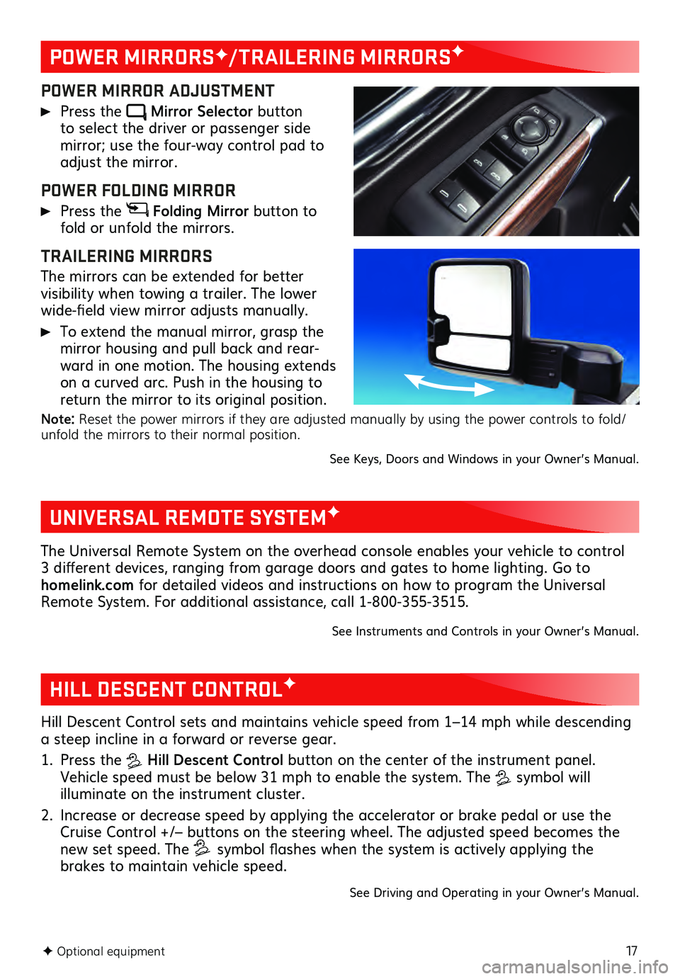
POWER MIRROR ADJUSTMENT
Press the Mirror Selector button to select the driver or passenger side mirror; use the four-way control pad to adjust the mirror.
POWER FOLDING MIRROR
Press the Folding Mirror button to
fold or unfold the mirrors.
TRAILERING MIRRORS
The mirrors can be extended for better visibility when towing a trailer. The lower
wide-field view mirror adjusts manually.
To extend the manual mirror, grasp the
mirror housing and pull back and rear -
ward in one motion. The housing extends
on a curved arc. Push in the housing to
return the mirror to its original position.
Note: Reset the power mirrors if they are adjusted manually by using the power controls to fold/
unfold the mirrors to their normal position.
See Keys, Doors and Windows in your Owner’s Manual.
UNIVERSAL REMOTE SYSTEMF
The Universal Remote System on the overhead console enables your vehicle to control
3 different devices, ranging from garage doors and gates to home lighting. Go to
homelink.com for detailed videos and instructions on how to program the Universal
Remote System. For additional assistance, call 1-800-355-3515.
See Instruments and Controls in your Owner’s Manual.
HILL DESCENT CONTROLF
Hill Descent Control sets and maintains vehicle speed from 1–14 mph while descending
a steep incline in a forward or reverse gear.
1. Press the Hill Descent Control button on the center of the instrument panel.
Vehicle speed must be below 31 mph to enable the system. The
symbol will illuminate on the instrument cluster.
2. Increase or decrease speed by applying the accelerator or brake pedal or use the Cruise Control +/– buttons on the steering wheel. The adjusted speed becomes the
new set speed. The symbol flashes when the system is actively applying the
brakes to maintain vehicle speed.
See Driving and Operating in your Owner’s Manual.
Page 18 of 20
18F Optional equipment
TRAILERINGF
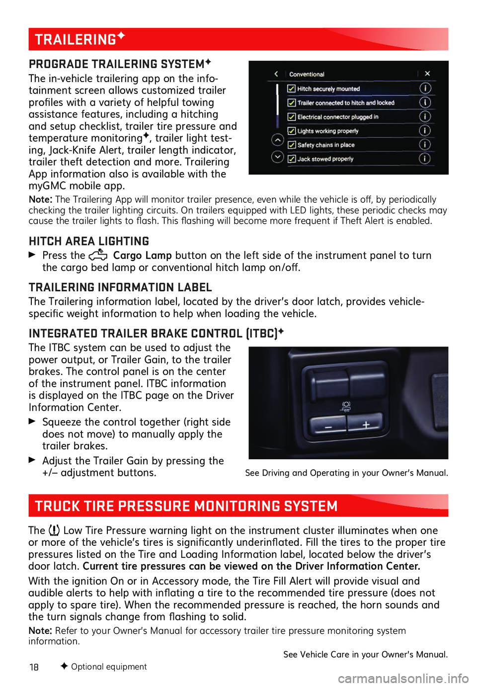
PROGRADE TRAILERING SYSTEMF
The in-vehicle trailering app on the info-
tainment screen allows customized trailer
profiles with a variety of helpful towing
assistance features, including a hitching
and setup checklist, trailer tire pressure and
temperature monitoring
F, trailer light test-
ing, Jack-Knife Alert, trailer length indicator,
trailer theft detection and more. Trailering
App information also is available with the
myGMC mobile app.
Note: The Trailering App will monitor trailer presence, even while the vehicle is off, by periodically
checking the trailer lighting circuits. On trailers equipped with LED lights, these periodic checks may
cause the trailer lights to flash. This flashing will become more frequent if Theft Alert is enabled.
HITCH AREA LIGHTING
Press the Cargo Lamp button on the left side of the instrument panel to turn
the cargo bed lamp or conventional hitch lamp on/off.
TRAILERING INFORMATION LABEL
The Trailering information label, located by the driver’s door latch, provides vehicle-
specific weight information to help when loading the vehicle.
INTEGRATED TRAILER BRAKE CONTROL (ITBC)F
The ITBC system can be used to adjust the
power output, or Trailer Gain, to the trailer
brakes. The control panel is on the center
of the instrument panel. ITBC information
is displayed on the ITBC page on the Driver
Information Center.
Squeeze the control together (right s ide does not move) to manually apply the
trailer brakes.
Adjust the Trailer Gain by pressing the +/– adjustment buttons. See Driving and Operating in your Owner’s Manual.
TRUCK TIRE PRESSURE MONITORING SYSTEM
The Low Tire Pressure warning light on the instrument cluster illuminates when one
or more of the vehicle’s tires is significantly underinflated. Fill the tires to the proper tire
pressures listed on the Tire and Loading Information label, located below the driver’s
door latch. Current tire pressures can be viewed on the Driver Information Center.
With the ignition On or in Accessory mode, the Tire Fill Alert will provide visual and
audible alerts to help with inflating a tire to the recommended tire pressure (does not apply to spare tire). When the recommended pressure is reached, the horn sounds and
the turn signals change from flashing to solid.
Note: Refer to your Owner’s Manual for accessory trailer tire pressure monitoring system
information.
See Vehicle Care in your Owner’s Manual.
Page 19 of 20
19
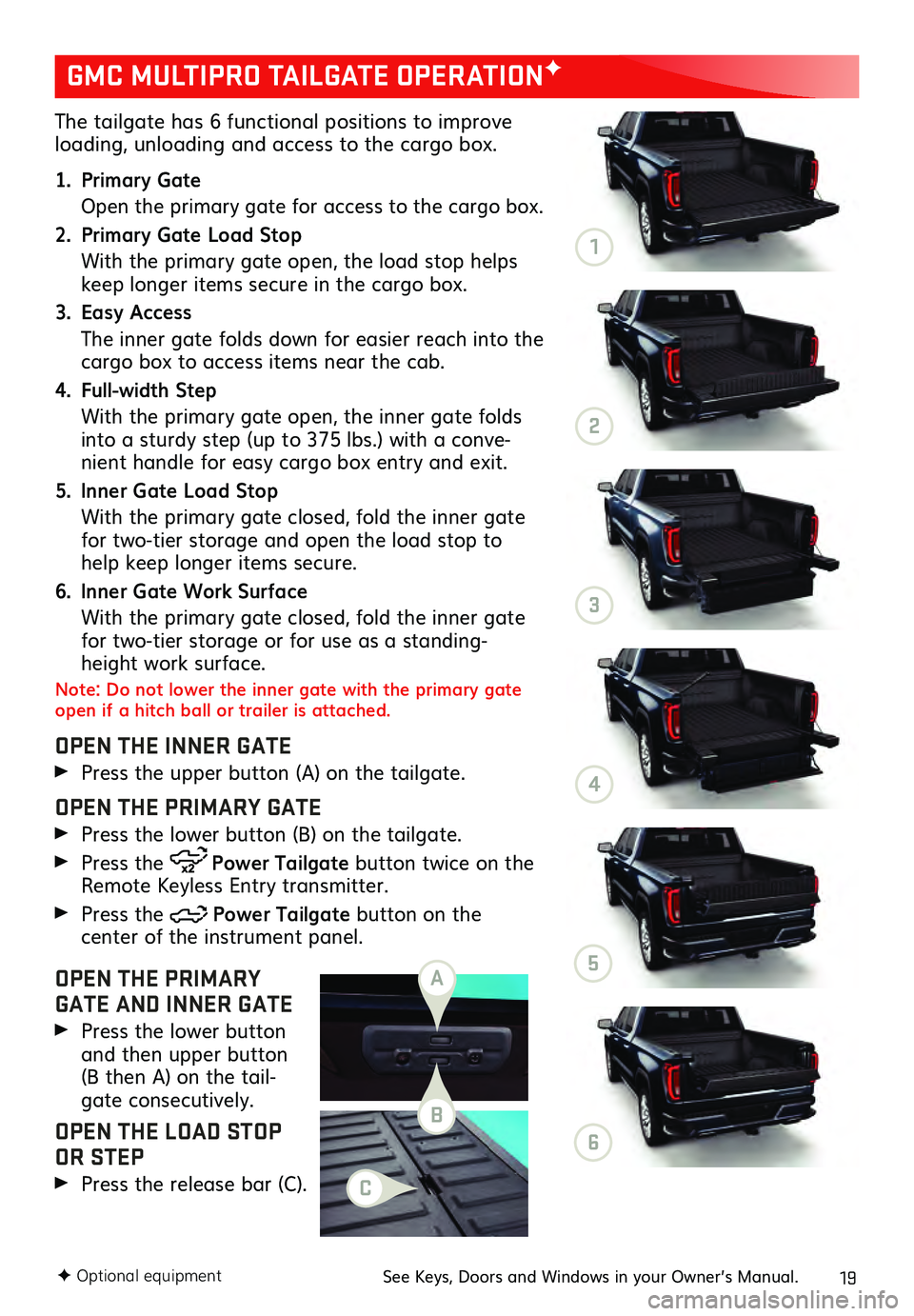
The tailgate has 6 functional positions to improve loading, unloading and access to the cargo box.
1. Primary Gate
Open the primary gate for ac cess to the cargo box.
2. Primary Gate Load Stop
With the primary gate open, the load stop helps keep longer items secure in the cargo box.
3. Easy Access
The inner ga te folds down for easier reach into the cargo box to access items near the cab.
4. Full-width Step
With the primary gate open, the inner gate folds into a sturdy step (up to 375 lbs.) with a conve-
nient handle for easy cargo box entry and exit.
5. Inner Gate Load Stop
With the primary gate closed, fold the inner gate for two-tier storage and open the load stop to
help keep longer items secure.
6. Inner Gate Work Surface
With the primary gate closed, fold the inner gate for two-tier storage or for use as a standing-
height work surface.
Note: Do not lower the inner gate with the primary gate
open if a hitch ball or trailer is attached.
OPEN THE INNER GATE
Press the upper button (A) on the tailgate.
OPEN THE PRIMARY GATE
Press the lower button (B) on the tailgate.
Press the Power Tailgate button twice on the
Remote Keyless Entry transmitter.
Press the Power Tailgate button on the center of the instrument panel.
OPEN THE PRIMARY
GATE AND INNER GATE
Press the lower button and then upper button
(B then A) on the tail -
gate consecutively.
OPEN THE LOAD STOP
OR STEP
Press the release bar (C).
GMC MULTIPRO TAILGATE OPERATIONF
F Optional equipmentSee Keys, Doors and Windows in your Owner’s Manual.
A
B
C
1
2
3
4
5
6