GMC TERRAIN 2010 Owner's Manual
Manufacturer: GMC, Model Year: 2010, Model line: TERRAIN, Model: GMC TERRAIN 2010Pages: 410, PDF Size: 2.55 MB
Page 301 of 410

Vehicle Care 9-27
3. Try to start the engine in eachgear. The vehicle should start
only in P (Park) or N (Neutral).
If the vehicle starts in any other
position, contact your dealer/
retailer for service.
Automatic Transmission
Shift Lock Control
System Check
{WARNING
When you are doing this
inspection, the vehicle could
move suddenly. If the vehicle
moves, you or others could be
injured.
1. Before starting this check, be sure there is enough room
around the vehicle. It should be
parked on a level surface. 2. Firmly apply the parking brake.
See Parking Brake
on
page 8‑40.
Be ready to apply the regular
brake immediately if the vehicle
begins to move.
3. With the engine off, turn the ignition to ON/RUN, but do not
start the engine. Without
applying the regular brake, try to
move the shift lever out of
P (Park) with normal effort. If the
shift lever moves out of P (Park),
contact your dealer/retailer for
service.
Ignition Transmission
Lock Check
While parked, and with the parking
brake set, try to turn the ignition to
LOCK/OFF in each shift lever
position.
.The ignition should turn to
LOCK/OFF only when the shift
lever is in P (Park).
.The ignition key should come
out only in LOCK/OFF.
Contact your dealer/retailer if
service is required.
Page 302 of 410
9-28 Vehicle Care
Park Brake and P (Park)
Mechanism Check
{WARNING
When you are doing this check,
the vehicle could begin to move.
You or others could be injured
and property could be damaged.
Make sure there is room in front
of the vehicle in case it begins to
roll. Be ready to apply the regular
brake at once should the vehicle
begin to move.Park on a fairly steep hill, with the
vehicle facing downhill. Keeping
your foot on the regular brake, set
the parking brake.
.To check the parking brake's
holding ability: With the engine
running and the transmission in
N (Neutral), slowly remove foot
pressure from the regular brake
pedal. Do this until the vehicle is
held by the parking brake only.
.To check the P (Park)
mechanism's holding ability:
With the engine running, shift to
P (Park). Then release the
parking brake followed by the
regular brake.
Contact your dealer/retailer if
service is required.
Wiper Blade Replacement
Windshield wiper blades should be
inspected for wear and cracking.
See Scheduled Maintenance
on
page 10‑2for more information.
Replacement blades come in
different types and are removed in
different ways. For proper type
and length, see Maintenance
Replacement Parts on page 10‑9.
Notice: Allowing the wiper blade
arm to touch the windshield when
no wiper blade is installed could
damage the windshield. Any
damage that occurs would not be
covered by your warranty. Do not
allow the wiper blade arm to
touch the windshield.
Page 303 of 410
Vehicle Care 9-29
Front Wiper Blade
Replacement
To replace the front wiper blades:
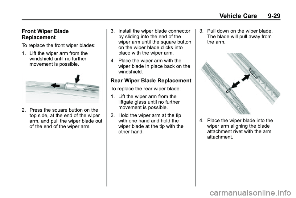
1. Lift the wiper arm from thewindshield until no further
movement is possible.
2. Press the square button on thetop side, at the end of the wiper
arm, and pull the wiper blade out
of the end of the wiper arm. 3. Install the wiper blade connector
by sliding into the end of the
wiper arm until the square button
on the wiper blade clicks into
place with the wiper arm.
4. Place the wiper arm with the wiper blade in place back on the
windshield.
Rear Wiper Blade Replacement
To replace the rear wiper blade:
1. Lift the wiper arm from theliftgate glass until no further
movement is possible.
2. Hold the wiper arm at the tip with one hand and hold the
wiper blade at the tip with the
other hand. 3. Pull down on the wiper blade.
The blade will pull away from
the arm.
4. Place the wiper blade into the
wiper arm aligning the blade
attachment rivet with the arm
attachment.
Page 304 of 410

9-30 Vehicle Care
5. Align the wiper blade with thearm and hold both ends of the
arm while gently squeezing until
the blade snaps into place.
Do not apply excessive force
during this operation.
Reposition the blade in the arm
and repeat, if blade is not
correctly positioned.
6. Place the wiper arm with the wiper blade attached back on
the liftgate glass.Headlamp Aiming
The headlamp aiming system has
been preset at the factory.
If the vehicle is damaged in an
accident, the aim of the headlamps
may be affected and adjustment
may be necessary.
It is recommended that a dealer/
retailer adjust the headlamps. To
re-aim the headlamps yourself, use
the following procedure.
The vehicle should be properly
prepared as follows. The vehicle:
.Should be placed so the
headlamps are 7.6 m (25 ft) from
a light colored wall.
.Must have all four tires on a
level surface which is level all
the way to the wall.
.Should be placed so it is
perpendicular to the wall or other
flat surface.
.Should not have any snow, ice,
or mud on it.
.Should be fully assembled and
all other work stopped while
headlamp aiming is being
performed.
.Should be normally loaded with
a full tank of fuel and one person
or 75 kg (160 lbs) sitting in the
driver's seat.
.Tires should be properly inflated.
Headlamp aiming is done with the
vehicle's low-beam headlamps. The
high-beam headlamps will be
correctly aimed if the low-beam
headlamps are aimed properly.
Page 305 of 410
Vehicle Care 9-31
To adjust the vertical aim, do the
following:
1. Open the hood. SeeHood
on
page 9‑5for more information.
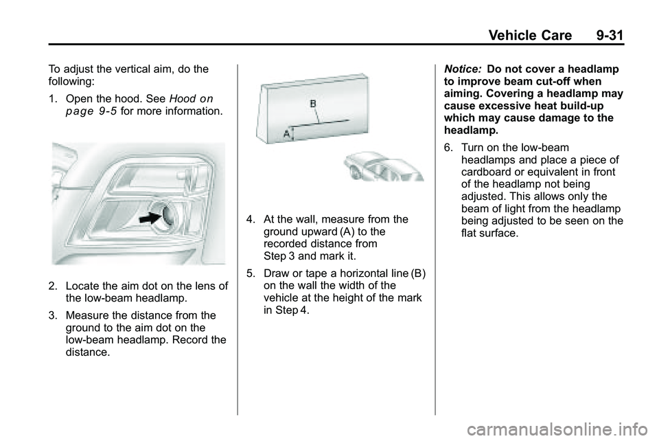
2. Locate the aim dot on the lens of the low‐beam headlamp.
3. Measure the distance from the ground to the aim dot on the
low‐beam headlamp. Record the
distance.
4. At the wall, measure from the
ground upward (A) to the
recorded distance from
Step 3 and mark it.
5. Draw or tape a horizontal line (B) on the wall the width of the
vehicle at the height of the mark
in Step 4. Notice:
Do not cover a headlamp
to improve beam cut-off when
aiming. Covering a headlamp may
cause excessive heat build-up
which may cause damage to the
headlamp.
6. Turn on the low-beam
headlamps and place a piece of
cardboard or equivalent in front
of the headlamp not being
adjusted. This allows only the
beam of light from the headlamp
being adjusted to be seen on the
flat surface.
Page 306 of 410
9-32 Vehicle Care
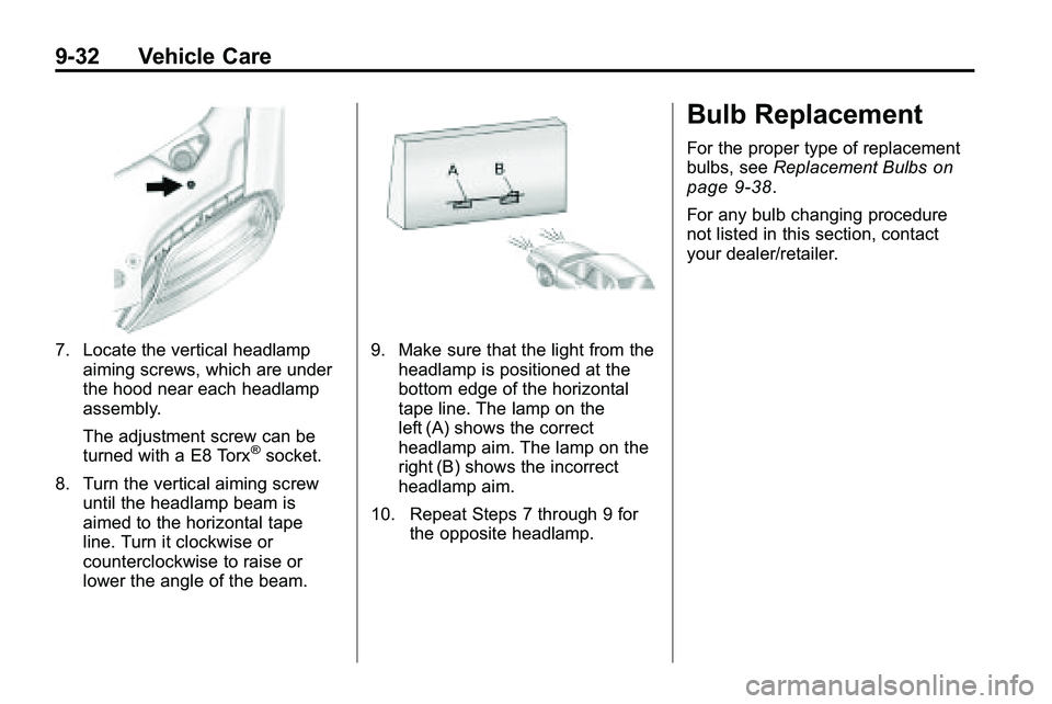
7. Locate the vertical headlampaiming screws, which are under
the hood near each headlamp
assembly.
The adjustment screw can be
turned with a E8 Torx
®socket.
8. Turn the vertical aiming screw until the headlamp beam is
aimed to the horizontal tape
line. Turn it clockwise or
counterclockwise to raise or
lower the angle of the beam.
9. Make sure that the light from theheadlamp is positioned at the
bottom edge of the horizontal
tape line. The lamp on the
left (A) shows the correct
headlamp aim. The lamp on the
right (B) shows the incorrect
headlamp aim.
10. Repeat Steps 7 through 9 for the opposite headlamp.
Bulb Replacement
For the proper type of replacement
bulbs, see Replacement Bulbson
page 9‑38.
For any bulb changing procedure
not listed in this section, contact
your dealer/retailer.
Page 307 of 410

Vehicle Care 9-33
Headlamps, Front Turn
Signal, Sidemarker, and
Parking Lamps
A. Low-Beam Headlamp
B. High-Beam headlamp
C. Side Marker Lamp
D. Park/Turn Signal LampTo replace:
1. Turn the tire to reach the access
port cap located in the front of
wheel well cover.A. Screw
B. Access Port Cap
2. Remove screw (A) and turn the access port cap (B)
counterclockwise to remove.
3. If replacing a low/high headlamp bulb, remove the dust cover cap
from the back of the headlamp
housing by turning the cap
counterclockwise. 4. Turn the low/high beam or
park/turn signal bulb socket
counterclockwise to remove from
the lamp assembly.
5. Turn the sidemarker bulb socket clockwise to remove from the
lamp assembly.
6. Remove the bulb from the socket or disconnect bulb
assembly from harness
connector.
7. Install new bulb.
8. Reinstall the low/high beam or park/turn signal bulb socket to
the lamp assembly, turning
clockwise.
9. Reinstall the sidemarker bulb socket to the lamp assembly,
turning clockwise.
10. Replace the dust cover cap on headlamps.
11. Reinstall the wheel well cover access port cap and secure by
installing screw.
Page 308 of 410
9-34 Vehicle Care
Fog Lamps
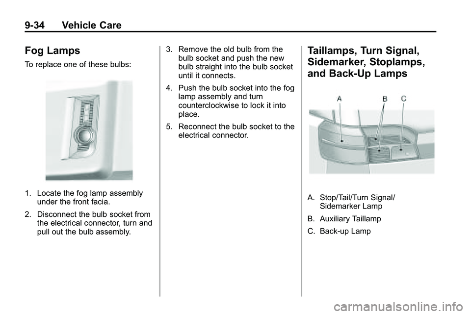
To replace one of these bulbs:
1. Locate the fog lamp assemblyunder the front facia.
2. Disconnect the bulb socket from the electrical connector, turn and
pull out the bulb assembly. 3. Remove the old bulb from the
bulb socket and push the new
bulb straight into the bulb socket
until it connects.
4. Push the bulb socket into the fog lamp assembly and turn
counterclockwise to lock it into
place.
5. Reconnect the bulb socket to the electrical connector.
Taillamps, Turn Signal,
Sidemarker, Stoplamps,
and Back-Up Lamps
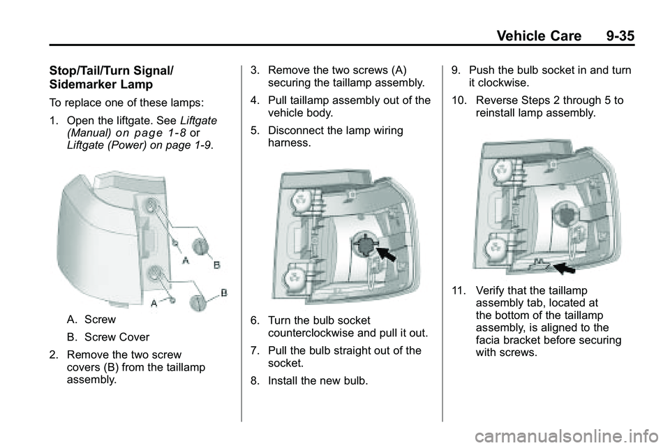
A. Stop/Tail/Turn Signal/Sidemarker Lamp
B. Auxiliary Taillamp
C. Back-up Lamp
Page 309 of 410
Vehicle Care 9-35
Stop/Tail/Turn Signal/
Sidemarker Lamp
To replace one of these lamps:
1. Open the liftgate. SeeLiftgate
(Manual)
on page 1‑8or
Liftgate (Power) on page 1‑9.
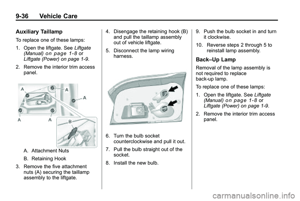
A. Screw
B. Screw Cover
2. Remove the two screw covers (B) from the taillamp
assembly. 3. Remove the two screws (A)
securing the taillamp assembly.
4. Pull taillamp assembly out of the vehicle body.
5. Disconnect the lamp wiring harness.6. Turn the bulb socketcounterclockwise and pull it out.
7. Pull the bulb straight out of the socket.
8. Install the new bulb. 9. Push the bulb socket in and turn
it clockwise.
10. Reverse Steps 2 through 5 to reinstall lamp assembly.
11. Verify that the taillampassembly tab, located at
the bottom of the taillamp
assembly, is aligned to the
facia bracket before securing
with screws.
Page 310 of 410
9-36 Vehicle Care
Auxiliary Taillamp
To replace one of these lamps:
1. Open the liftgate. SeeLiftgate
(Manual)
on page 1‑8or
Liftgate (Power) on page 1‑9.
2. Remove the interior trim access panel.
A. Attachment Nuts
B. Retaining Hook
3. Remove the five attachment nuts (A) securing the taillamp
assembly to the liftgate. 4. Disengage the retaining hook (B)
and pull the taillamp assembly
out of vehicle liftgate.
5. Disconnect the lamp wiring harness.
6. Turn the bulb socketcounterclockwise and pull it out.
7. Pull the bulb straight out of the socket.
8. Install the new bulb. 9. Push the bulb socket in and turn
it clockwise.
10. Reverse steps 2 through 5 to reinstall lamp assembly.
Back–Up Lamp
Removal of the lamp assembly is
not required to replace
back-up lamp.
To replace one of these lamps:
1. Open the liftgate. See Liftgate
(Manual)
on page 1‑8or
Liftgate (Power) on page 1‑9.
2. Remove the interior trim access panel.