clock GMC TERRAIN 2021 User Guide
[x] Cancel search | Manufacturer: GMC, Model Year: 2021, Model line: TERRAIN, Model: GMC TERRAIN 2021Pages: 377, PDF Size: 9.13 MB
Page 280 of 377

GMC Terrain/Terrain Denali Owner Manual(GMNA-Localizing-U.S./Canada/
Mexico-14420055) - 2021 - CRC - 11/13/20
Vehicle Care 279
5. Turn the bulb socket counterclockwiseand pull it out.
6. Pull the bulb straight out of the socket.
7. Push the replacement bulb straight into the bulb socket.
8. Push the bulb socket in and turn it clockwise.
9. Reverse Steps 2–5 to reinstall the lamp assembly.
License Plate Lamp
Lamp Assembly
Bulb Assembly
1. Bulb Socket
2. Bulb
3. Lamp Assembly
To replace one of these bulbs:
1. Open the liftgate partway. See Liftgate
0 17.
2. Push the lamp assembly outboard to remove.
3. Pull the lamp assembly down to remove it from the liftgate.
4. Turn the bulb socket (1) counterclockwise to remove it from the lamp assembly (3).
5. Pull the bulb (2) straight out of the bulb socket (1).
6. Push the replacement bulb straight into the bulb socket and turn the bulb socket
clockwise to install it into the lamp
assembly.
7. Push the lamp assembly into the liftgate engaging the clip side first.
8. Push on the lamp side opposite the clip until the lamp assembly snaps into place.
Page 307 of 377

GMC Terrain/Terrain Denali Owner Manual(GMNA-Localizing-U.S./Canada/
Mexico-14420055) - 2021 - CRC - 11/13/20
306 Vehicle Care
9. Power Plug
10. Air Only Hose
Tire Sealant
Read and follow the safe handling
instructions on the label adhered to the tire
sealant canister (4).
Check the tire sealant expiration date on the
tire sealant canister. The tire sealant
canister (4) should be replaced before its
expiration date. Replacement tire sealant
canisters are available at your local dealer.
There is only enough sealant to seal one
tire. After usage, the tire sealant canister
must be replaced.
Using the Tire Sealant and Compressor
Kit to Temporarily Seal and Inflate a
Punctured Tire
When using the tire sealant and compressor
kit during cold temperatures, warm the kit
in a heated environment for five minutes.
This will help to inflate the tire faster.
If a tire goes flat, avoid further tire and
wheel damage by driving slowly to a level
place. Turn on the hazard warning flashers.
SeeHazard Warning Flashers 0119.
See If a Tire Goes Flat 0303 for other
important safety warnings.
Do not remove any objects that have
penetrated the tire.
1. Remove the tire sealant canister (4) and compressor from its storage location. See
Storing the Tire Sealant and Compressor
Kit 0310.
2. Remove the air only hose (10) and the power plug (9) from the bottom of the
compressor.
3. Place the compressor on the ground near the flat tire.
4. Attach the air only hose (10) to thesealant canister inlet valve (1) by turning
it clockwise until tight.
Page 308 of 377
GMC Terrain/Terrain Denali Owner Manual(GMNA-Localizing-U.S./Canada/
Mexico-14420055) - 2021 - CRC - 11/13/20
Vehicle Care 307
5. Slide the base of the tire sealantcanister (3) into the slot on the top of
the compressor (6) to hold it upright.
Make sure the tire valve stem is
positioned close to the ground so the
hose will reach it.
6. Remove the valve stem cap from the flat tire by turning it counterclockwise.
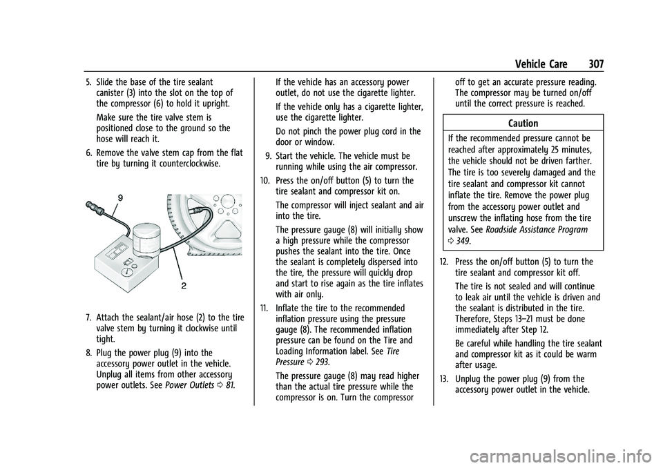
7. Attach the sealant/air hose (2) to the tirevalve stem by turning it clockwise until
tight.
8. Plug the power plug (9) into the accessory power outlet in the vehicle.
Unplug all items from other accessory
power outlets. See Power Outlets081. If the vehicle has an accessory power
outlet, do not use the cigarette lighter.
If the vehicle only has a cigarette lighter,
use the cigarette lighter.
Do not pinch the power plug cord in the
door or window.
9. Start the vehicle. The vehicle must be running while using the air compressor.
10. Press the on/off button (5) to turn the tire sealant and compressor kit on.
The compressor will inject sealant and air
into the tire.
The pressure gauge (8) will initially show
a high pressure while the compressor
pushes the sealant into the tire. Once
the sealant is completely dispersed into
the tire, the pressure will quickly drop
and start to rise again as the tire inflates
with air only.
11. Inflate the tire to the recommended inflation pressure using the pressure
gauge (8). The recommended inflation
pressure can be found on the Tire and
Loading Information label. See Tire
Pressure 0293.
The pressure gauge (8) may read higher
than the actual tire pressure while the
compressor is on. Turn the compressor off to get an accurate pressure reading.
The compressor may be turned on/off
until the correct pressure is reached.
Caution
If the recommended pressure cannot be
reached after approximately 25 minutes,
the vehicle should not be driven farther.
The tire is too severely damaged and the
tire sealant and compressor kit cannot
inflate the tire. Remove the power plug
from the accessory power outlet and
unscrew the inflating hose from the tire
valve. See
Roadside Assistance Program
0 349.
12. Press the on/off button (5) to turn the tire sealant and compressor kit off.
The tire is not sealed and will continue
to leak air until the vehicle is driven and
the sealant is distributed in the tire.
Therefore, Steps 13–21 must be done
immediately after Step 12.
Be careful while handling the tire sealant
and compressor kit as it could be warm
after usage.
13. Unplug the power plug (9) from the accessory power outlet in the vehicle.
Page 309 of 377

GMC Terrain/Terrain Denali Owner Manual(GMNA-Localizing-U.S./Canada/
Mexico-14420055) - 2021 - CRC - 11/13/20
308 Vehicle Care
14. Turn the sealant/air hose (2)counterclockwise to remove it from the
tire valve stem.
15. Replace the tire valve stem cap.
16. Remove the tire sealant canister (4) from the slot on top of the compressor (6).
17. Turn the air only hose (10) counterclockwise to remove it from the
tire sealant canister inlet valve (1).
18. Turn the sealant/air hose (2) clockwise onto the sealant canister inlet valve (1)
to prevent sealant leakage.
19. Return the air only hose (10) and power plug (9) back to their original storage
location.
20. If the flat tire was able to inflate to therecommended inflation pressure, remove
the maximum speed label from the
sealant canister and place it in a highly
visible location. Do not exceed the speed on this label
until the damaged tire is repaired or
replaced.
21. Return the equipment to its original storage location in the vehicle.
22. Immediately drive the vehicle 8 km (5 mi) to distribute the sealant in
the tire.
23. Stop at a safe location and check the tire pressure. Refer to Steps 1–10 under
“Using the Tire Sealant and Compressor
Kit without Sealant to Inflate a Tire (Not
Punctured).”
If the tire pressure has fallen more than
68 kPa (10 psi) below the recommended
inflation pressure, stop driving the
vehicle. The tire is too severely damaged
and the tire sealant cannot seal the tire.
SeeRoadside Assistance Program 0349.
If the tire pressure has not dropped
more than 68 kPa (10 psi) from the
recommended inflation pressure, inflate
the tire to the recommended inflation
pressure.
24. Wipe off any sealant from the wheel, tire, or vehicle. 25. Dispose of the used tire sealant
canister (4) at a local dealer or in
accordance with local state codes and
practices.
26. Replace it with a new canister available from your dealer.
27. After temporarily sealing a tire using the tire sealant and compressor kit, take the
vehicle to an authorized dealer within
161 km (100 mi) of driving to have the
tire repaired or replaced.
Using the Tire Sealant and Compressor
Kit without Sealant to Inflate a Tire (Not
Punctured)
The kit includes:
Page 310 of 377
GMC Terrain/Terrain Denali Owner Manual(GMNA-Localizing-U.S./Canada/
Mexico-14420055) - 2021 - CRC - 11/13/20
Vehicle Care 309
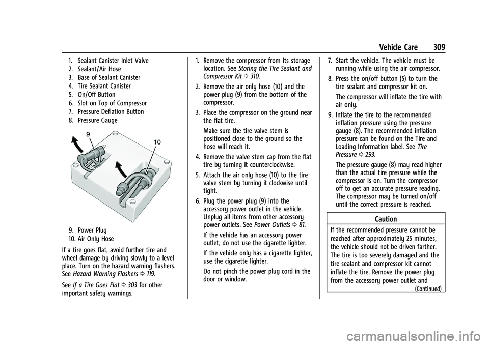
1. Sealant Canister Inlet Valve
2. Sealant/Air Hose
3. Base of Sealant Canister
4. Tire Sealant Canister
5. On/Off Button
6. Slot on Top of Compressor
7. Pressure Deflation Button
8. Pressure Gauge
9. Power Plug
10. Air Only Hose
If a tire goes flat, avoid further tire and
wheel damage by driving slowly to a level
place. Turn on the hazard warning flashers.
SeeHazard Warning Flashers 0119.
See If a Tire Goes Flat 0303 for other
important safety warnings. 1. Remove the compressor from its storage
location. See Storing the Tire Sealant and
Compressor Kit 0310.
2. Remove the air only hose (10) and the power plug (9) from the bottom of the
compressor.
3. Place the compressor on the ground near the flat tire.
Make sure the tire valve stem is
positioned close to the ground so the
hose will reach it.
4. Remove the valve stem cap from the flat tire by turning it counterclockwise.
5. Attach the air only hose (10) to the tire valve stem by turning it clockwise until
tight.
6. Plug the power plug (9) into the accessory power outlet in the vehicle.
Unplug all items from other accessory
power outlets. See Power Outlets081.
If the vehicle has an accessory power
outlet, do not use the cigarette lighter.
If the vehicle only has a cigarette lighter,
use the cigarette lighter.
Do not pinch the power plug cord in the
door or window. 7. Start the vehicle. The vehicle must be
running while using the air compressor.
8. Press the on/off button (5) to turn the tire sealant and compressor kit on.
The compressor will inflate the tire with
air only.
9. Inflate the tire to the recommended inflation pressure using the pressure
gauge (8). The recommended inflation
pressure can be found on the Tire and
Loading Information label. See Tire
Pressure 0293.
The pressure gauge (8) may read higher
than the actual tire pressure while the
compressor is on. Turn the compressor
off to get an accurate pressure reading.
The compressor may be turned on/off
until the correct pressure is reached.
Caution
If the recommended pressure cannot be
reached after approximately 25 minutes,
the vehicle should not be driven farther.
The tire is too severely damaged and the
tire sealant and compressor kit cannot
inflate the tire. Remove the power plug
from the accessory power outlet and
(Continued)
Page 311 of 377
GMC Terrain/Terrain Denali Owner Manual(GMNA-Localizing-U.S./Canada/
Mexico-14420055) - 2021 - CRC - 11/13/20
310 Vehicle Care
Caution (Continued)
unscrew the inflating hose from the tire
valve. SeeRoadside Assistance Program
0 349.
10. Press the on/off button (5) to turn the tire sealant and compressor kit off.
Be careful while handling the compressor
as it could be warm after usage.
11. Unplug the power plug (9) from the accessory power outlet in the vehicle.
12. Turn the air only hose (10) counterclockwise to remove it from the
tire valve stem.
13. Replace the tire valve stem cap.
14. Return the air only hose (10) and power plug (9) back to their original storage
location.
15. Return the equipment to its original storage location in the vehicle.
The tire sealant and compressor kit has
accessory adapters located in a
compartment on the bottom of its housing
that can be used to inflate air mattresses,
balls, etc.
Storing the Tire Sealant and
Compressor Kit
To access the tire sealant and
compressor kit: 1. Open the liftgate. See Liftgate017.
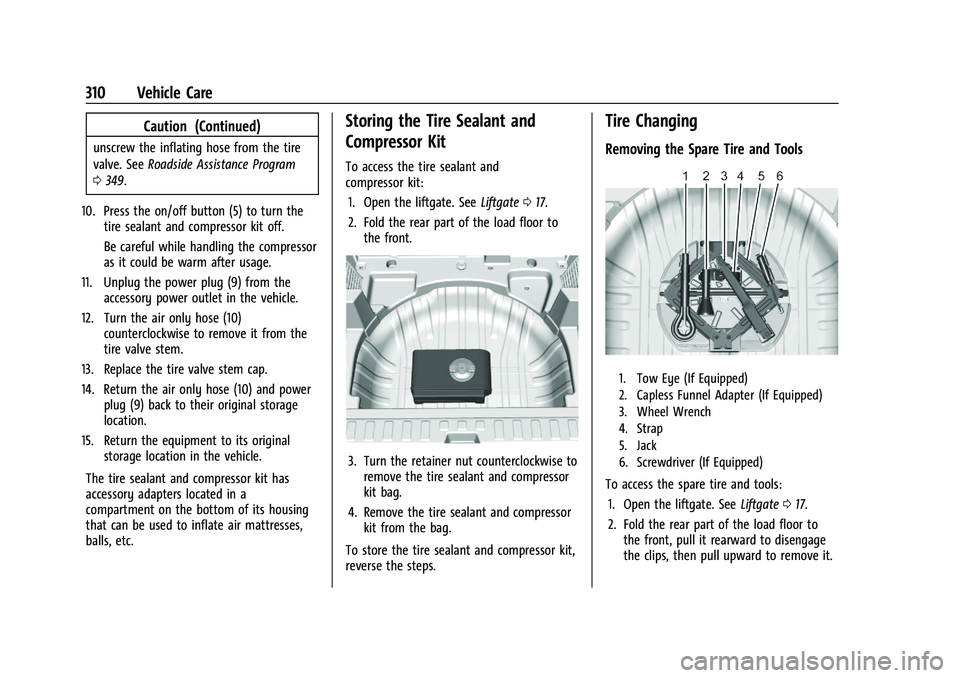
2. Fold the rear part of the load floor to the front.
3. Turn the retainer nut counterclockwise toremove the tire sealant and compressor
kit bag.
4. Remove the tire sealant and compressor kit from the bag.
To store the tire sealant and compressor kit,
reverse the steps.
Tire Changing
Removing the Spare Tire and Tools
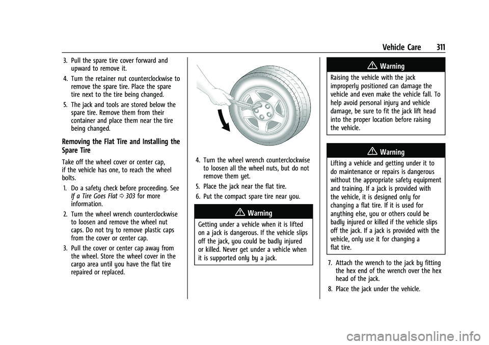
1. Tow Eye (If Equipped)
2. Capless Funnel Adapter (If Equipped)
3. Wheel Wrench
4. Strap
5. Jack
6. Screwdriver (If Equipped)
To access the spare tire and tools: 1. Open the liftgate. See Liftgate017.
2. Fold the rear part of the load floor to the front, pull it rearward to disengage
the clips, then pull upward to remove it.
Page 312 of 377
GMC Terrain/Terrain Denali Owner Manual(GMNA-Localizing-U.S./Canada/
Mexico-14420055) - 2021 - CRC - 11/13/20
Vehicle Care 311
3. Pull the spare tire cover forward andupward to remove it.
4. Turn the retainer nut counterclockwise to remove the spare tire. Place the spare
tire next to the tire being changed.
5. The jack and tools are stored below the spare tire. Remove them from their
container and place them near the tire
being changed.
Removing the Flat Tire and Installing the
Spare Tire
Take off the wheel cover or center cap,
if the vehicle has one, to reach the wheel
bolts.
1. Do a safety check before proceeding. See If a Tire Goes Flat 0303 for more
information.
2. Turn the wheel wrench counterclockwise to loosen and remove the wheel nut
caps. Do not try to remove plastic caps
from the cover or center cap.
3. Pull the cover or center cap away from the wheel. Store the wheel cover in the
cargo area until you have the flat tire
repaired or replaced.4. Turn the wheel wrench counterclockwiseto loosen all the wheel nuts, but do not
remove them yet.
5. Place the jack near the flat tire.
6. Put the compact spare tire near you.
{Warning
Getting under a vehicle when it is lifted
on a jack is dangerous. If the vehicle slips
off the jack, you could be badly injured
or killed. Never get under a vehicle when
it is supported only by a jack.
{Warning
Raising the vehicle with the jack
improperly positioned can damage the
vehicle and even make the vehicle fall. To
help avoid personal injury and vehicle
damage, be sure to fit the jack lift head
into the proper location before raising
the vehicle.
{Warning
Lifting a vehicle and getting under it to
do maintenance or repairs is dangerous
without the appropriate safety equipment
and training. If a jack is provided with
the vehicle, it is designed only for
changing a flat tire. If it is used for
anything else, you or others could be
badly injured or killed if the vehicle slips
off the jack. If a jack is provided with the
vehicle, only use it for changing a
flat tire.
7. Attach the wrench to the jack by fitting the hex end of the wrench over the hex
head of the jack.
8. Place the jack under the vehicle.
Page 313 of 377

GMC Terrain/Terrain Denali Owner Manual(GMNA-Localizing-U.S./Canada/
Mexico-14420055) - 2021 - CRC - 11/13/20
312 Vehicle Care
Caution
Make sure that the jack lift head is in the
correct position or you may damage your
vehicle. The repairs would not be covered
by your warranty.
Rear Shown, Front Similar
9. Position the jack lift head at the jacklocation nearest the flat tire. The location
is indicated by a notch in the vertical
bottom edge of the body side sheet
metal.
The notches in the jack must align with
the notch in the rocker pinch weld. The
jack lift head lifts on the inward side of
the pinch weld flange.
The jack must not be used in any other
position.10. Raise the vehicle by turning the jack handle clockwise. Raise the vehicle far
enough off the ground so there is
enough room for the road tire to clear
the ground.
Page 314 of 377
GMC Terrain/Terrain Denali Owner Manual(GMNA-Localizing-U.S./Canada/
Mexico-14420055) - 2021 - CRC - 11/13/20
Vehicle Care 313
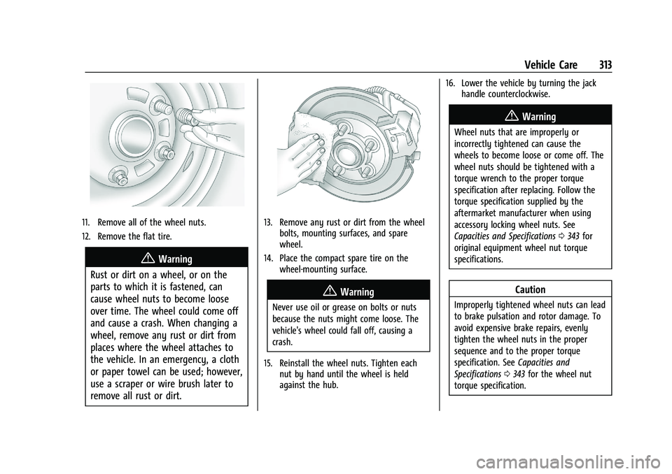
11. Remove all of the wheel nuts.
12. Remove the flat tire.
{Warning
Rust or dirt on a wheel, or on the
parts to which it is fastened, can
cause wheel nuts to become loose
over time. The wheel could come off
and cause a crash. When changing a
wheel, remove any rust or dirt from
places where the wheel attaches to
the vehicle. In an emergency, a cloth
or paper towel can be used; however,
use a scraper or wire brush later to
remove all rust or dirt.
13. Remove any rust or dirt from the wheel bolts, mounting surfaces, and spare
wheel.
14. Place the compact spare tire on the wheel-mounting surface.
{Warning
Never use oil or grease on bolts or nuts
because the nuts might come loose. The
vehicle's wheel could fall off, causing a
crash.
15. Reinstall the wheel nuts. Tighten each nut by hand until the wheel is held
against the hub. 16. Lower the vehicle by turning the jack
handle counterclockwise.
{Warning
Wheel nuts that are improperly or
incorrectly tightened can cause the
wheels to become loose or come off. The
wheel nuts should be tightened with a
torque wrench to the proper torque
specification after replacing. Follow the
torque specification supplied by the
aftermarket manufacturer when using
accessory locking wheel nuts. See
Capacities and Specifications 0343 for
original equipment wheel nut torque
specifications.
Caution
Improperly tightened wheel nuts can lead
to brake pulsation and rotor damage. To
avoid expensive brake repairs, evenly
tighten the wheel nuts in the proper
sequence and to the proper torque
specification. See Capacities and
Specifications 0343 for the wheel nut
torque specification.
Page 368 of 377

GMC Terrain/Terrain Denali Owner Manual(GMNA-Localizing-U.S./Canada/-
Mexico-14420055) - 2021 - CRC - 11/13/20
Index 367
Climate Control Systems (cont'd)Dual Automatic . . . . . . . . . . . . . . . . . . . . . . . . 180
Heating . . . . . . . . . . . . . . . . . . . . . . . . . . . . . . . . 178
Clock . . . . . . . . . . . . . . . . . . . . . . . . . . . . . . . . . . . . . .81
Cluster, Instrument . . . . . . . . . . . . . . . . . . . 85, 88
Collision Damage Repair . . . . . . . . . . . . . . . . . 352
Compact Spare Tire . . . . . . . . . . . . . . . . . . . . . . . 315
Compartments Storage . . . . . . . . . . . . . . . . . . . . . . . . . . . . . . . . . 74
Compass . . . . . . . . . . . . . . . . . . . . . . . . . . . . . . . . . . .81
Compressor Kit, Tire Sealant . . . . . . . . . . . . . 305
Connected Services Connections . . . . . . . . . . . . . . . . . . . . . . . . . . . 363
Diagnostics . . . . . . . . . . . . . . . . . . . . . . . . . . . . 364
Navigation . . . . . . . . . . . . . . . . . . . . . . . . . . . . . 362
Connections
Connected Services . . . . . . . . . . . . . . . . . . . . 363
Control Hill Descent . . . . . . . . . . . . . . . . . . . . . . . . . . . . . 217
Traction and Electronic Stability . . . . . . . 214
Control Light
Hill Descent . . . . . . . . . . . . . . . . . . . . . . . . . . . . . 96
Control of a Vehicle . . . . . . . . . . . . . . . . . . . . . 188
Controls Steering Wheel . . . . . . . . . . . . . . . . . . . . . . . . 126
Convenience Net . . . . . . . . . . . . . . . . . . . . . . . . . . 76
Convex Mirrors . . . . . . . . . . . . . . . . . . . . . . . . . . . 24 Coolant
Engine Temperature Gauge . . . . . . . . . . . . . 91
Cooling . . . . . . . . . . . . . . . . . . . . . . . . . . . . . . 178, 180
Cooling System . . . . . . . . . . . . . . . . . . . . . . . . . . 267
Courtesy Lamps . . . . . . . . . . . . . . . . . . . . . . . . . . 120
Courtesy Transportation Program . . . . . . . . . 351
Cover Cargo . . . . . . . . . . . . . . . . . . . . . . . . . . . . . . . . . . . 75
Coverage Explanations . . . . . . . . . . . . . . . . . . . 150
Covers Winter . . . . . . . . . . . . . . . . . . . . . . . . . . . . . . . . . 202
Cruise Control . . . . . . . . . . . . . . . . . . . . . . . . . . . 220 Light . . . . . . . . . . . . . . . . . . . . . . . . . . . . . . . . . . . 100
Cruise Control, Adaptive . . . . . . . . . . . . . . . . . 222
Cupholders . . . . . . . . . . . . . . . . . . . . . . . . . . . . . . . 74
Customer Assistance . . . . . . . . . . . . . . . . . . . . . 348 Offices . . . . . . . . . . . . . . . . . . . . . . . . . . . . . . . . . 348
Text Telephone (TTY) Users . . . . . . . . . . . . 348
Customer Information Publications Ordering Information . . . . . 353
Customer Satisfaction Procedure . . . . . . . . . 346
Cybersecurity . . . . . . . . . . . . . . . . . . . . . . . . . . . . 355
D
Damage Repair, Collision . . . . . . . . . . . . . . . . . 352
Danger, Warning, and Caution . . . . . . . . . . . . . .2
Data Collection
Infotainment System . . . . . . . . . . . . . . . . . . 356 Data Collection (cont'd)
OnStar . . . . . . . . . . . . . . . . . . . . . . . . . . . . . . . . . 356
Data Recorders, Event . . . . . . . . . . . . . . . . . . . 356
Database Coverage Explanations . . . . . . . . . 150
Daytime Running Lamps (DRL) . . . . . . . . . . . . 118
Defensive Driving . . . . . . . . . . . . . . . . . . . . . . . . .187
Delayed Locking . . . . . . . . . . . . . . . . . . . . . . . . . . .16
Destination . . . . . . . . . . . . . . . . . . . . . . . . . . . . . . .142
Diagnostics Connected Services . . . . . . . . . . . . . . . . . . . . 364
Distracted Driving . . . . . . . . . . . . . . . . . . . . . . . . .187
Dome Lamps . . . . . . . . . . . . . . . . . . . . . . . . . . . . . 120
Door Ajar Light . . . . . . . . . . . . . . . . . . . . . . . . . . . . . . 100
Delayed Locking . . . . . . . . . . . . . . . . . . . . . . . . 16
Locks . . . . . . . . . . . . . . . . . . . . . . . . . . . . . . . . . . . 14
Power Locks . . . . . . . . . . . . . . . . . . . . . . . . . . . . 16
Drive Belt Routing, Engine . . . . . . . . . . . . . . . 345
Drive Systems All-Wheel Drive . . . . . . . . . . . . . . . . . . . . 212, 274
Driver
Teen . . . . . . . . . . . . . . . . . . . . . . . . . . . . . . . . . . . 167
Driver Assistance Systems . . . . . . . . . . . . . . . . 231
Driver Behavior . . . . . . . . . . . . . . . . . . . . . . . . . . 186
Driver Information Center (DIC) . . . . . 100, 105
Driver Mode Control . . . . . . . . . . . . . . . . . . . . . .218
Driving Assistance Systems . . . . . . . . . . . . . . . . . . . . 237