charging GMC YUKON HYBRID 2010 Owners Manual
[x] Cancel search | Manufacturer: GMC, Model Year: 2010, Model line: YUKON HYBRID, Model: GMC YUKON HYBRID 2010Pages: 120, PDF Size: 1.03 MB
Page 33 of 120
Section 4 Instrument Panel
Climate Controls. . . . . . . . . . . . . . . . . . . . . . . . . . . . . . . . . . . 4-2
Warning Lights, Gages, and Indicators . . . . . . . . . . .4-3
Instrument Panel Cluster . . . . . . . . . . . . . . . . . . . . . . . . 4-3
Tachometer . . . . . . . . . . . . . . . . . . . . . . . . . . . . . . . . . . . . . 4-4
Charging System Light . . . . . . . . . . . . . . . . . . . . . . . . . . 4-4
Fuel Economy Gage . . . . . . . . . . . . . . . . . . . . . . . . . . . . 4-5
Brake System Warning Light . . . . . . . . . . . . . . . . . . . . 4-6
Antilock Brake System (ABS) Warning Light . . . . 4-7
StabiliTrak
®Indicator Light . . . . . . . . . . . . . . . . . . . . . . 4-7 Engine Coolant Temperature Gage . . . . . . . . . . . . . 4-8
Oil Pressure Gage . . . . . . . . . . . . . . . . . . . . . . . . . . . . . . 4-8
Oil Pressure Light . . . . . . . . . . . . . . . . . . . . . . . . . . . . . 4-10
Fuel Gage . . . . . . . . . . . . . . . . . . . . . . . . . . . . . . . . . . . . . 4-11
Driver Information Center (DIC) . . . . . . . . . . . . . . . . . .4-12
DIC Warnings and Messages . . . . . . . . . . . . . . . . . . 4-12
Audio System(s) . . . . . . . . . . . . . . . . . . . . . . . . . . . . . . . . . . 4-14
Navigation/Radio System . . . . . . . . . . . . . . . . . . . . . . 4-14
4-1
Page 36 of 120
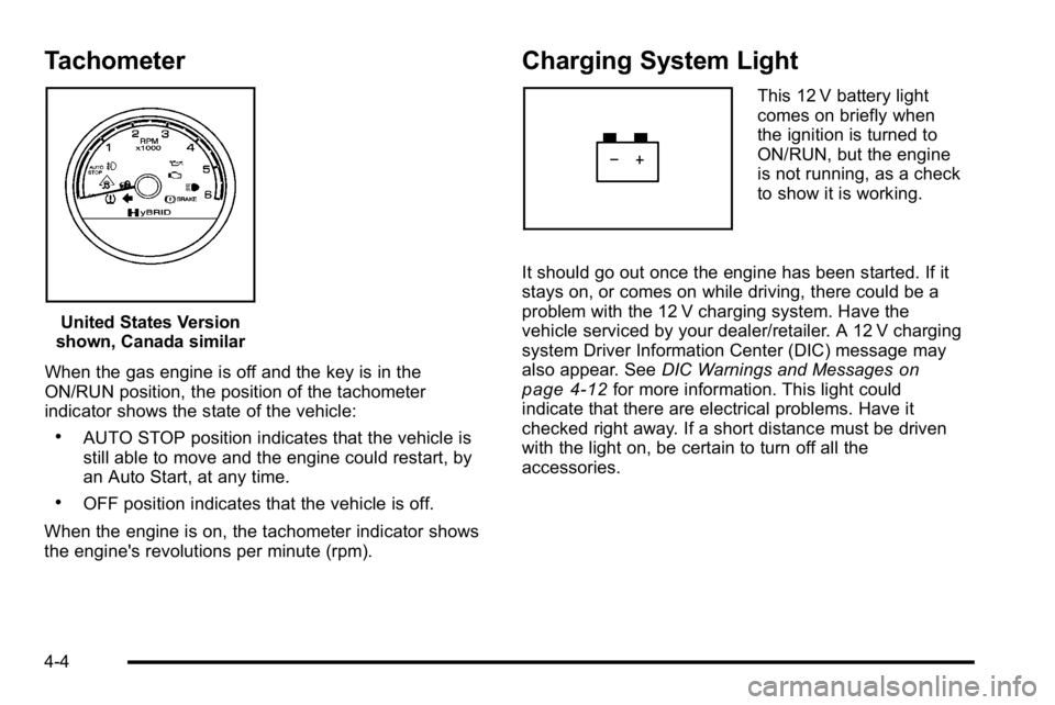
Tachometer
United States Version
shown, Canada similar
When the gas engine is off and the key is in the
ON/RUN position, the position of the tachometer
indicator shows the state of the vehicle:
.AUTO STOP position indicates that the vehicle is
still able to move and the engine could restart, by
an Auto Start, at any time.
.OFF position indicates that the vehicle is off.
When the engine is on, the tachometer indicator shows
the engine's revolutions per minute (rpm).
Charging System Light
This 12 V battery light
comes on briefly when
the ignition is turned to
ON/RUN, but the engine
is not running, as a check
to show it is working.
It should go out once the engine has been started. If it
stays on, or comes on while driving, there could be a
problem with the 12 V charging system. Have the
vehicle serviced by your dealer/retailer. A 12 V charging
system Driver Information Center (DIC) message may
also appear. See DIC Warnings and Messages
on
page 4‑12for more information. This light could
indicate that there are electrical problems. Have it
checked right away. If a short distance must be driven
with the light on, be certain to turn off all the
accessories.
4-4
Page 44 of 120
Driver Information Center (DIC)
Trip/Fuel Menu Items
Press the trip/fuel button to display the Trip/Fuel Menu
items. For more items see“DIC Operation and
Displays” in the owner manual.
BATTERY VOLTAGE
This display shows the current battery voltage. If the
voltage is in the normal range, the value will display.
For example, the display may read BATTERY
VOLTAGE 13.2 VOLTS. If the voltage is high or low,
the display will read HIGH or LOW. Your vehicle's
charging system regulates voltage based on the state
of the battery. The battery voltage may fluctuate when
viewing this information on the DIC. This is normal.
See“Charging System Light” in the owner manual for
more information. If there is a problem with the battery
charging system, the DIC will display a message.
See DIC Warnings and Messages on page 4‑12.
INST ECON (Instantaneous Economy)
This display normally shows instantaneous fuel
economy. When the vehicle is in Auto Stop mode
AUTO STOP or INST ECON = 99 MPG (l/00km) will be
displayed. See Starting the Vehicle
on page 3‑3for
more information.
DIC Warnings and Messages
Warning messages are displayed on the DIC to notify
the driver that the status of the vehicle has changed
and that some action may be needed by the driver to
correct the condition. If there is more than one message
that needs to be displayed they will appear one after
another.
Some messages may not require immediate action, but
you can press any of the DIC buttons on the instrument
panel or the trip odometer reset stem to acknowledge
that you received the messages and to clear them from
the display.
Some messages cannot be cleared from the DIC
display because they are more urgent. These
messages require action before they can be cleared.
You should take any messages that appear on the
display seriously and remember that clearing the
messages will only make the messages disappear, not
correct the problem.
For information on other DIC messages, see “DIC
Warnings and Messages” in the owner manual Index.
HOOD OPEN
If the hood is not fully closed or there is a problem with
the hood switch, this message will be displayed. Close
the hood to clear the message. If the HOOD OPEN
message continues to be displayed after verifying the
4-12
Page 45 of 120
hood is closed, you should have the hood switch
serviced. Failure to service the hood switch properly
can result in an Auto Start condition.
Auto Stops will be disabled when this message is
displayed. If the vehicle is in auto stop mode when this
message appears, the engine will instantly start.
OIL PRESSURE LOW STOP ENGINE
If engine oil pressure is low, this message will be
displayed on the DIC. Stop the vehicle as soon as
safely possible and do not operate it until the cause of
the low oil pressure has been corrected. Check your oil
level as soon as possible and have your vehicle
serviced. See“Engine Oil”in the owner manual Index.
SERVICE 4 WHEEL DRIVE
This message may display if a problem occurs with the
four-wheel-drive system. If this message appears, stop
as soon as possible and turn off the vehicle. Make sure
the key is in the LOCK/OFF position for at least
one minute and then restart the vehicle and check for
the message on the DIC display. If the message is still
displayed or appears again when you begin driving,
the four-wheel-drive system needs service. See your
dealer/retailer.
SERVICE BATTERY CHARGING
SYSTEM
If the 12V battery system faults or fails this message will
appear on the DIC. The battery/charging system light
will appear in the instrument panel cluster. See “Battery
Warning Light” in the owner manual Index. Driving with
this message on could drain the battery. Have the
electrical system checked as soon as possible.
SERVICE BRAKE SYSTEM
This message will be displayed if there is a problem
with the brake system. You will still be able to brake, but
it will be noticeably more difficult. Pull off the road to a
safe location and have your vehicle towed to the
nearest dealer/retailer for service. See “Brakes,”
“Brake System Warning Light,” and“ABS Brake System
Warning Light” in the owner manual Index.
SERVICE HYBRID SYSTEM
If this message is displayed on the DIC, the vehicle may
continue to operate, but you need to have it serviced as
soon as possible.
SERVICE POWER STEERING
This message displays if a problem has been detected
with the electric power steering. Have your vehicle
serviced by your dealer/retailer immediately.
4-13
Page 46 of 120
Audio System(s)
Navigation/Radio System
For vehicles with a navigation radio system, see the
Navigation System manual for more information.
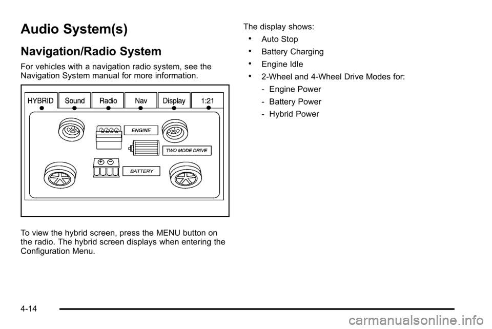
To view the hybrid screen, press the MENU button on
the radio. The hybrid screen displays when entering the
Configuration Menu.The display shows:
.Auto Stop
.Battery Charging
.Engine Idle
.2‐Wheel and 4‐Wheel Drive Modes for:
‐
Engine Power
‐ Battery Power
‐ Hybrid Power
4-14
Page 74 of 120
Jump Starting
{WARNING:
Personal injury, death, or damage to the vehicle
can result if you try jump starting or using a
battery charger on the high voltage hybrid battery.
Use only the 12-volt battery for jump starting and
charging.
If the vehicle's 12‐volt battery has run down, you may
want to use another vehicle and some jumper cables to
start your vehicle. Use the following steps to do it safely.
{WARNING:
Batteries can hurt you. They can be dangerous
because:
.They contain acid that can burn you.
.They contain gas that can explode or ignite.
.They contain enough electricity to burn you.
If you do not follow these steps exactly, some or
all of these things can hurt you.
Notice: Ignoring these steps could result in costly
damage to the vehicle that would not be covered by
the warranty.
Trying to start the vehicle by pushing or pulling it
will not work, and it could damage the vehicle.
1. Check the other vehicle. It must have a 12‐volt battery with a negative ground system.
Notice: If the other vehicle's system is not a 12-volt
system with a negative ground, both vehicles can
be damaged. Only use vehicles with 12-volt systems
with negative grounds to jump start your vehicle.
6-18
Page 117 of 120

A
Alternating CurrentPower Outlet . . . . . . . . . . . . . . . . . . . . . . . . . . . . . . . . . . . . . . 3-2
Antilock Brake System (ABS) Warning Light . . . . . . . . . . . . . . . . . . . . . . . . . . . . . . . . . . . . . . 4-7
Audio System(s) Navigation/Radio System . . . . . . . . . . . . . . . . . . . . . . . . . 4-14
Automatic Transmission, Fluid . . . . . . . . . . . . . . . . . . . . . . .6-5
B
Battery . . . . . . . . . . . . . . . . . . . . . . . . . . . . . . . . . . . . . . . . . . . . 6-16
Belt Routing, Engine . . . . . . . . . . . . . . . . . . . . . . . . . . . . . . . . .7-2
Brakes . . . . . . . . . . . . . . . . . . . . . . . . . . . . . . . . . . . . . . . . . . . . . 6-13 Regenerative Braking . . . . . . . . . . . . . . . . . . . . . . . . . . . . . 3-18
System Warning Light . . . . . . . . . . . . . . . . . . . . . . . . . . . . . 4-6
Bulb Replacement Taillamps, Turn Signal, Stoplamps andBack-up Lamps . . . . . . . . . . . . . . . . . . . . . . . . . . . . . . . . . 6-24
C
Canadian Owners . . . . . . . . . . . . . . . . . . . . . . . . . . . . . . . . . . . . . ii
Capacities and Specifications . . . . . . . . . . . . . . . . . . . . . . 6-57
Chains, Tire . . . . . . . . . . . . . . . . . . . . . . . . . . . . . . . . . . . . . . . 6-34
Charging System Light . . . . . . . . . . . . . . . . . . . . . . . . . . . . . .4-4
Climate Controls . . . . . . . . . . . . . . . . . . . . . . . . . . . . . . . . . . . . .4-2
Compressor Kit, Tire Sealant . . . . . . . . . . . . . . . . 6-35, 6-45
Coolant
Engine Temperature Gage . . . . . . . . . . . . . . . . . . . . . . . . . 4-8
Coolant Surge Tank Pressure Cap, (DMCM) . . . . . . . . .6-8
Cooling System, (DMCM) . . . . . . . . . . . . . . . . . . . . . . . . . . . .6-9
D
Drive Motor/Generator Control Module (DMCM) Coolant Surge Tank Pressure Cap . . . . . . . . . . . . . . . . .6-8
Drive Motor/Generator Control Module (DMCM) Cooling System . . . . . . . . . . . . . . . . . . . . . . . . . . . . . . . . . . . .6-9
Driver Information Center (DIC) . . . . . . . . . . . . . . . . . . . . 4-12
Warnings and Messages . . . . . . . . . . . . . . . . . . . . . . . . . 4-12
i - 1
Page 118 of 120

E
EngineCompartment Overview . . . . . . . . . . . . . . . . . . . . . . . . . . . . 6-4
Coolant Temperature Gage . . . . . . . . . . . . . . . . . . . . . . . . 4-8
Drive Belt Routing . . . . . . . . . . . . . . . . . . . . . . . . . . . . . . . . . 7-2
Engine Coolant Heater . . . . . . . . . . . . . . . . . . . . . . . . . . . . 3-17
F
Flat Tire . . . . . . . . . . . . . . . . . . . . . . . . . . . . . . . . . . . . . . . . . . . 6-34
Fluid Power Steering . . . . . . . . . . . . . . . . . . . . . . . . . . . . . . . . . . . 6-13
Four-Wheel Drive . . . . . . . . . . . . . . . . . . . . . . . . . . . . . . . . . . 3-10
Fuel Gage . . . . . . . . . . . . . . . . . . . . . . . . . . . . . . . . . . . . . . . . . . . . . 4-11
Fuel Economy Gage . . . . . . . . . . . . . . . . . . . . . . . . . . . . . . . . .4-5
G
Gages Engine Coolant Temperature . . . . . . . . . . . . . . . . . . . . . . 4-8
Fuel . . . . . . . . . . . . . . . . . . . . . . . . . . . . . . . . . . . . . . . . . . . . . . 4-11
Fuel Economy . . . . . . . . . . . . . . . . . . . . . . . . . . . . . . . . . . . . . 4-5
Oil Pressure . . . . . . . . . . . . . . . . . . . . . . . . . . . . . . . . . . . . . . . 4-8
Tachometer . . . . . . . . . . . . . . . . . . . . . . . . . . . . . . . . . . . . . . . . 4-4
H
High Voltage Devices and Wiring . . . . . . . . . . . . . . . . . . . .6-3
I
Inflation - Tire Pressure . . . . . . . . . . . . . . . . . . . . . . . . . . . . 6-28
Instrument Panel Cluster . . . . . . . . . . . . . . . . . . . . . . . . . . . .4-3
Introduction . . . . . . . . . . . . . . . . . . . . . . . . . . . . . . . . . . . . . . . . . . . iii
J
Jump Starting . . . . . . . . . . . . . . . . . . . . . . . . . . . . . . . . . . . . . . 6-18
L
LightsAntilock Brake System (ABS) Warning . . . . . . . . . . . . . 4-7
Brake System Warning . . . . . . . . . . . . . . . . . . . . . . . . . . . . 4-6
Charging System . . . . . . . . . . . . . . . . . . . . . . . . . . . . . . . . . . 4-4
Oil Pressure . . . . . . . . . . . . . . . . . . . . . . . . . . . . . . . . . . . . . . 4-10
StabiliTrak
®Indicator . . . . . . . . . . . . . . . . . . . . . . . . . . . . . . 4-7
Lumbar Manual Controls . . . . . . . . . . . . . . . . . . . . . . . . . . . . . . . . . . . 2-2
i - 2