check engine GREAT WALL FLORID 2008 Workshop Manual
[x] Cancel search | Manufacturer: GREAT WALL, Model Year: 2008, Model line: FLORID, Model: GREAT WALL FLORID 2008Pages: 281, PDF Size: 43.97 MB
Page 227 of 281
Downloaded from www.Manualslib.com manuals search engine GWFLORID Maintenance Manual220
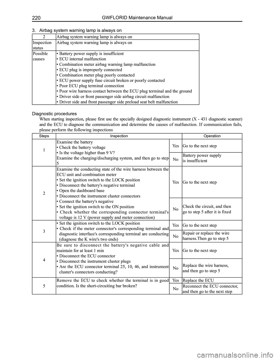
3. Airbag system warning lamp is always on
2Airbag system warning lamp is always on
Inspection
status
Airbag system warning lamp is always on
Possible
causes
• Battery power supply is insufficient
• ECU internal malfunction
• Combination meter airbag warning lamp malfunction
• ECU plug is improperly connected
• Combination meter plug poorly contacted
• ECU power supply fuse circuit broken or poorly contacted
• Poor ECU plug terminal connection
• Poor wire harness contact between the ECU plug terminal and the ground
• Driver side or front passenger side airbag circuit malfunction
• Driver side and front passenger side preload seat belt malfunction
Diagnostic procedures
When starting inspection, please first use the specially designed diagnostic instrument (X - 431 diagnostic scanner)
and the ECU to diagnose the communication and determine the causes of malfunction. If communication fails,
please perform the following inspections
StepsInspection Operation
1
Examine the battery
• Check the battery voltage
• Is the voltage higher than 9 V?
Examine the charging/discharging system, and then go to step
5
YesGo to the next step
NoBattery power supply
is insufficient
2
Examine the conducting state of the wire harness between the
ECU unit and combination meter
• Set the ignition switch to the LOCK position
• Disconnect the battery's negative terminal
• Open the dashboard base
• Disconnect the instrument cluster connectors
• Connect the battery's negative
• Set the ignition switch to the ON position
• Check whether the corresponding connector terminal's
voltage is 12 V (power supply and meter connection)
YesGo to the next step
NoCheck the circuit, and then
go to step 5 after it is fixed
3
• Set the ignition switch to the LOCK position
• Check if the meter connector's corresponding terminal and
diagnostic interface's corresponding terminal are conducting
(diagnose the K wire's two ends)
YesGo to the next step
NoRepair or replace the wire
harness.Then go to step 5
4
B e s u r e t o d i s c o n n e c t t h e b a t t e r y ' s n e g a t i v e c a b l e a n d
maintain for at least 1 min
• Disconnect the ECU connector
• Disconnect the instrument cluster plugs
• Are the ECU connector terminal 25, 10, 46, and instrument
cluster's connectors conducting?
YesGo to the next step
NoReplace the wire harness,
and then go to step 5
5
Remove the ECU to check whether the terminal is in good
condition. Is the short-circuiting bar broken?
YesReplace the ECU
NoReconnect the ECU connector,
and then go to the next step
Page 228 of 281
Downloaded from www.Manualslib.com manuals search engine 221Airbags
StepsInspection Operation
6
Check and make sure the malfunction symptom does not
appear again after they are repaired
• Set the ignition switch to the LOCK position
• Disconnect the battery's negative cable and maintain for at
least 1 min
• Connect all of the ECU plugs
• Connect the airbag subassembly plugs at the driver side
• Connect the airbag subassembly plugs at the passenger side
• Connect the driver and passenger side preload seat belt plugs
• Connect the clock spring plugs
• Connect the battery's negative cable
• Set the ignition switch to the ON position
• Does the airbag warning lamp work properly?
Yes
After the malfunction
is removed, explain the
maintenance procedure
to the client
No
Recheck the malfunction
symptom, if the malfunction
happens again, repeat
the repairing procedures
starting from the first step
4. Internal malfunction
Type
code 0D
Trouble
code >80
SRS airbag system unit internal malfunction
Detecting
conditions
Warning
• This malfunction's diagnosis requires a trouble code not to be shown prior to inspection. Use a DTC
to perform inspection. Performing this malfunction detection might cause operator injury or system
damage due to incorrect operation. Therefore, before inspection, please properly prepare.
• SRS airbag system electronic control unit circuit internal malfunction
Possible
causesSRS airbag system unit internal malfunction
OperationReplace the SRS airbag system unit. Refer to airbag system and SRS airba\
g system unit removal and installation
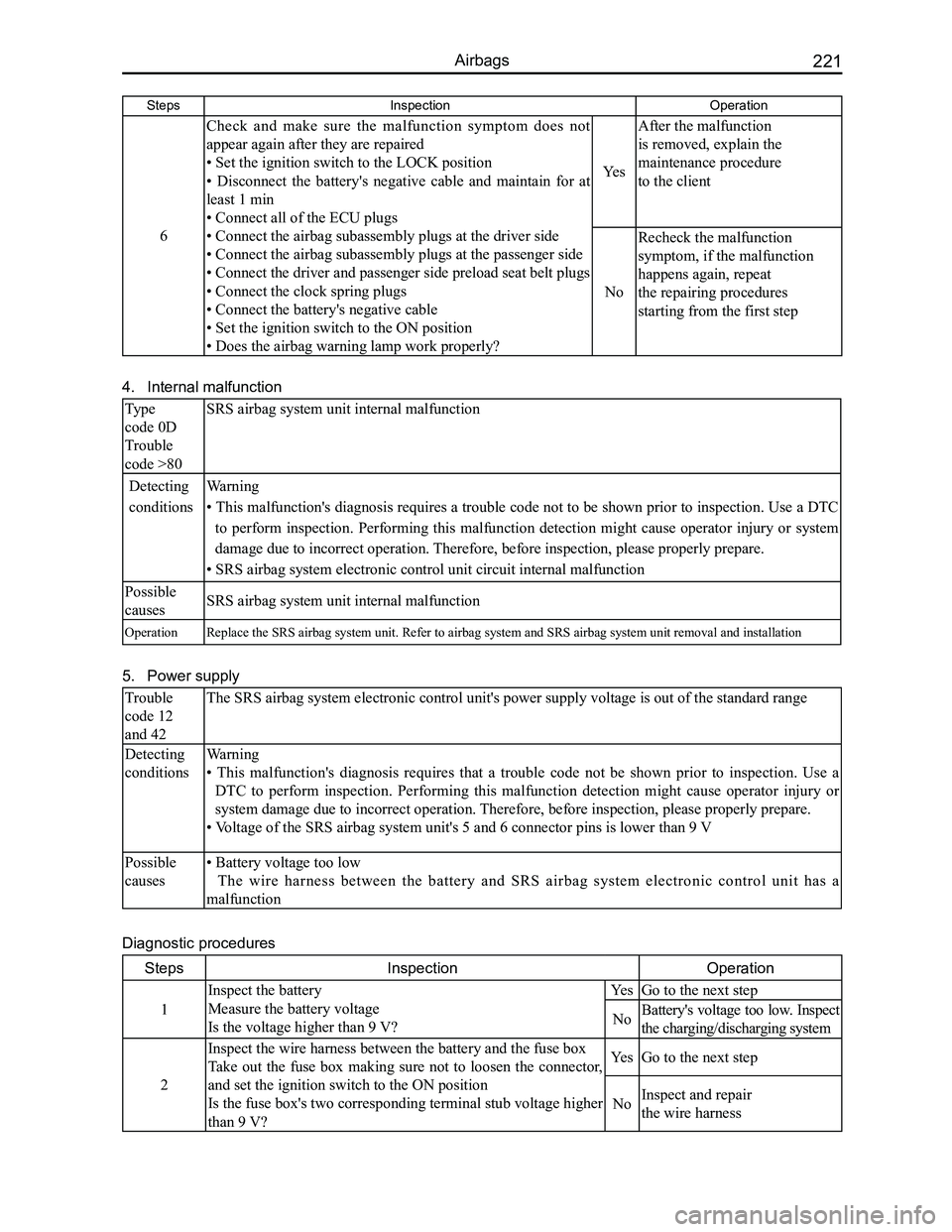
5. Power supply
Trouble
code 12
and 42
The SRS airbag system electronic control unit's power supply voltage is \
out of the standard range
Detecting
conditions
Warning
• This malfunction's diagnosis requires that a trouble code not be shown prior to inspection. Use a
DTC to perform inspection. Performing this malfunction detection might cause operator injury or
system damage due to incorrect operation. Therefore, before inspection, please properly prepare.
• Voltage of the SRS airbag system unit's 5 and 6 connector pins is lower than 9 V
Possible
causes
• Battery voltage too low
The wire harness between the battery and SRS airbag system electronic control unit has a
malfunction
Diagnostic procedures
StepsInspectionOperation
1
Inspect the battery
Measure the battery voltage
Is the voltage higher than 9 V?
YesGo to the next step
NoBattery's voltage too low. Inspect
the charging/discharging system
2
Inspect the wire harness between the battery and the fuse box
Take out the fuse box making sure not to loosen the connector,
and set the ignition switch to the ON position
Is the fuse box's two corresponding terminal stub voltage higher
than 9 V?
YesGo to the next step
NoInspect and repair
the wire harness
Page 230 of 281
Downloaded from www.Manualslib.com manuals search engine 223Airbags
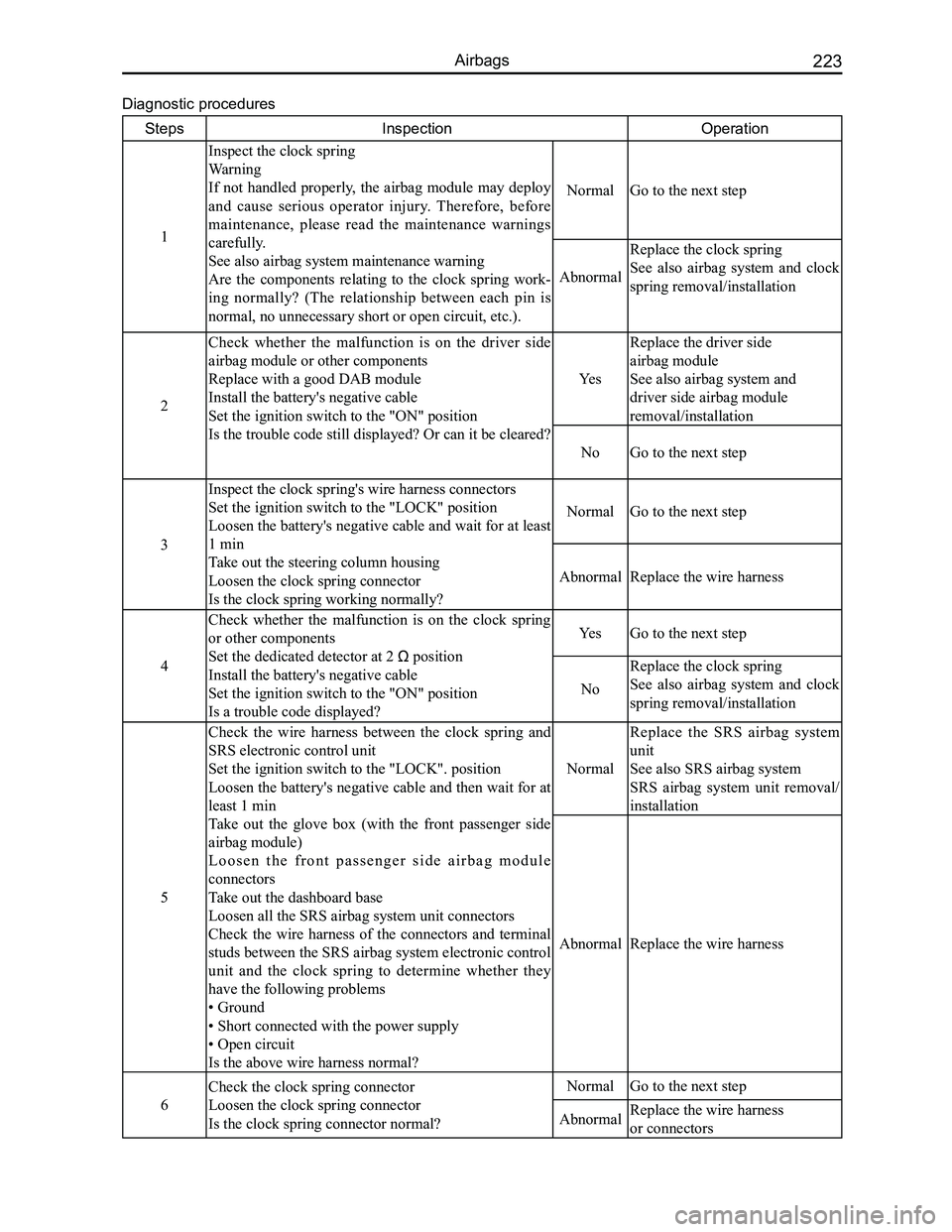
Diagnostic procedures
StepsInspectionOperation
1
Inspect the clock spring
Warning
If not handled properly, the airbag module may deploy
and cause serious operator injury. Therefore, before
maintenance, please read the maintenance warnings
carefully.
See also airbag system maintenance warning
Are the components relating to the clock spring work-
ing normally? (The relationship between each pin is
normal, no unnecessary short or open circuit, etc.).
NormalGo to the next step
Abnormal
Replace the clock spring
See also airbag system and clock
spring removal/installation
2
Check whether the malfunction is on the driver side
airbag module or other components
Replace with a good DAB module
Install the battery's negative cable
Set the ignition switch to the "ON" position
Is the trouble code still displayed? Or can it be cleared?
Yes
Replace the driver side
airbag module
See also airbag system and
driver side airbag module
removal/installation
NoGo to the next step
3
Inspect the clock spring's wire harness connectors
Set the ignition switch to the "LOCK" position
Loosen the battery's negative cable and wait for at least
1 min
Take out the steering column housing
Loosen the clock spring connector
Is the clock spring working normally?
NormalGo to the next step
AbnormalReplace the wire harness
4
Check whether the malfunction is on the clock spring
or other components
Set the dedicated detector at 2 Ω position
Install the battery's negative cable
Set the ignition switch to the "ON" position
Is a trouble code displayed?
YesGo to the next step
No
Replace the clock spring
See also airbag system and clock
spring removal/installation
5
Check the wire harness between the clock spring and
SRS electronic control unit
Set the ignition switch to the "LOCK". position
Loosen the battery's negative cable and then wait for at
least 1 min
Take out the glove box (with the front passenger side
airbag module)
L o o s e n t h e f r o n t p a s s e n g e r s i d e a i r b a g m o d u l e
connectors
Take out the dashboard base
Loosen all the SRS airbag system unit connectors
Check the wire harness of the connectors and terminal
studs between the SRS airbag system electronic control
unit and the clock spring to determine whether they
have the following problems
• Ground
• Short connected with the power supply
• Open circuit
Is the above wire harness normal?
Normal
Replace the SRS airbag system
unit
See also SRS airbag system
SRS airbag system unit removal/
installation
AbnormalReplace the wire harness
6
Check the clock spring connector
Loosen the clock spring connector
Is the clock spring connector normal?
NormalGo to the next step
AbnormalReplace the wire harness
or connectors
Page 231 of 281
Downloaded from www.Manualslib.com manuals search engine GWFLORID Maintenance Manual224
StepsInspectionOperation
7
Inspect the clock spring
Take the clock spring off
See also airbag system and clock spring removal/
installation
Inspect the clock spring
See also airbag system and clock spring inspection
Check the clock spring. Is it normal?
NormalGo to the next step
Abnormal
Replace the clock spring
See also airbag system and clock
spring removal/installation
8
Check the wire harness between the clock spring and
SRS electronic control unit
Set the ignition switch to the "LOCK" position
Loosen the battery's negative cable and then wait for at
least 1 min
Take the glove box off (with the front passenger side
airbag)
L o o s e n t h e f r o n t p a s s e n g e r s i d e a i r b a g m o d u l e
connectors
Take out the dashboard base
Loosen all the SRS airbag system unit connectors
Check the wire harness of the connectors' terminal
studs between the SRS electronic control unit and the
clock spring to see whether they have the following
problems.
• Ground
• Short connected with the power supply
• Open circuit
Is the above wire harness normal?
Normal
Replace the driver side
airbag module
See also SRS airbag system
Driver side airbag module
removal/installation
AbnormalReplace the wire harness
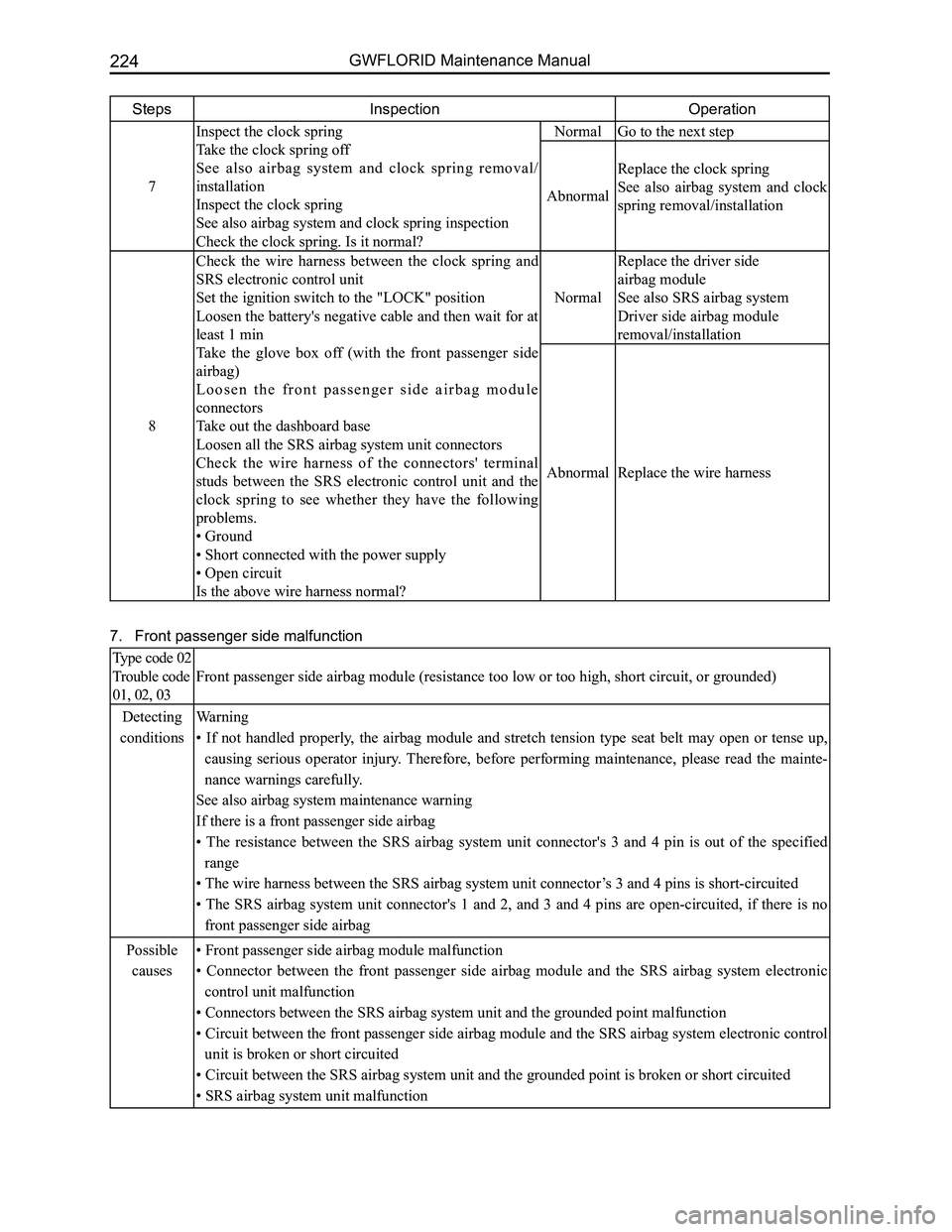
7. Front passenger side malfunction
Type code 02
Trouble code
01, 02, 03
Front passenger side airbag module (resistance too low or too high, sho\
rt circuit, or grounded)
Detecting
conditions
Warning
• If not handled properly, the airbag module and stretch tension type seat belt may open or tense up,
causing serious operator injury. Therefore, before performing maintenance, please read the mainte-
nance warnings carefully.
See also airbag system maintenance warning
If there is a front passenger side airbag
• The resistance between the SRS airbag system unit connector's 3 and 4 pin is out of the specified
range
• The wire harness between the SRS airbag system unit connector’s 3 and 4 pins is short-circuited
• The SRS airbag system unit connector's 1 and 2, and 3 and 4 pins are open-circuited, if there is no
front passenger side airbag
Possible
causes
• Front passenger side airbag module malfunction
• Connector between the front passenger side airbag module and the SRS airbag system electronic
control unit malfunction
• Connectors between the SRS airbag system unit and the grounded point malfunction
• Circuit between the front passenger side airbag module and the SRS airbag system electronic control
unit is broken or short circuited
• Circuit between the SRS airbag system unit and the grounded point is broken or short circuited
• SRS airbag system unit malfunction
Page 232 of 281
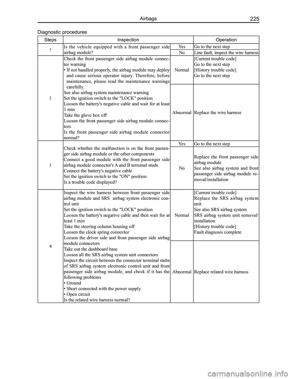
Downloaded from www.Manualslib.com manuals search engine 225Airbags
Diagnostic procedures
StepsInspectionOperation
1Is the vehicle equipped with a front passenger side
airbag module?
YesGo to the next step
NoLine fault, inspect the wire harness
2
Check the front passenger side airbag module connec-
tor warning
• If not handled properly, the airbag module may deploy
and cause serious operator injury. Therefore, before
maintenance, please read the maintenance warnings
carefully.
See also airbag system maintenance warning
Set the ignition switch to the "LOCK" position
Loosen the battery's negative cable and wait for at least
1 min
Take the glove box off
Loosen the front passenger side airbag module connec-
tors
Is the front passenger side airbag module connector
normal?
Normal
[Current trouble code]
Go to the next step
[History trouble code]
Go to the next step
AbnormalReplace the wire harness
3
Check whether the malfunction is on the front passen-
ger side airbag module or the other components
Connect a good module with the front passenger side
airbag module connector's A and B terminal studs
Connect the battery's negative cable
Set the ignition switch to the "ON" position
Is a trouble code displayed?
YesGo to the next step
No
Replace the front passenger side
airbag module
See also airbag system and front
passenger side airbag module re-
moval/installation
4
Inspect the wire harness between front passenger side
airbag module and SRS airbag system electronic con-
trol unit
Set the ignition switch to the "LOCK" position
Loosen the battery's negative cable and then wait for at
least 1 min
Take the steering column housing off
Loosen the clock spring connector
Loosen the driver side and front passenger side airbag
module connectors
Take out the dashboard base
Loosen all the SRS airbag system unit connectors
Inspect the circuit between the connector terminal stubs
of SRS airbag system electronic control unit and front
passenger side airbag module, and check if it has the
following problems
• Ground
• Short connected with the power supply
• Open circuit
Is the related wire harness normal?
Normal
[Current trouble code]
Replace the SRS airbag system
unit
See also SRS airbag system
SRS airbag system unit removal/
installation
[History trouble code]
Fault diagnosis complete
AbnormalReplace related wire harness
Page 233 of 281
Downloaded from www.Manualslib.com manuals search engine GWFLORID Maintenance Manual226
Vehicle Collision Diagnostics
Whether the airbag is deployed or not, vehicle collision diagnostic and maintenance must be conducted
according to the following procedures.
1. Check the SRS-ECU diagnostic signal
(a) Connect the diagnostic connector (X-431 diagnostic scanner).
(b) Read the diagnostic result with the X-431 diagnostic.
Caution: Due to impact, and when the battery's power supply is insufficient, the scanner will be unable
to communicate with the SRS-ECU. At this time, use an external power supply, or make sure to
perform inspection and maintenance on the dashboard's wire harness.
2. Maintenance sequence
When the airbag is deployed, the following components should be replaced\
.
(a) Driver side airbag module.
(b) Front passenger side airbag module.
(c) SRS-ECU.
(d) Driver side and front passenger side preload seat belts.
Inspect the following components, if anything is abnormal, replace with \
a new one.
(a) Clock spring.
(b) Steering wheel, steering column, and steering lower shaft components.
Installation status of the driver side airbag module regarding the steer\
ing wheel.
(a) Inspect whether the steering wheel's noise is abnormal, for improper movement, or abnormal cleara\
nce.
(b) Inspect whether the wire harness connectors are broken and whether the terminals are deformed.
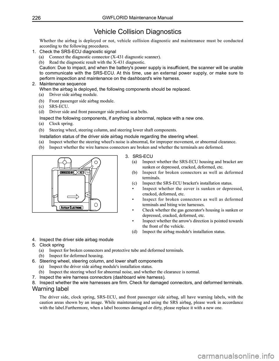
3. SRS-ECU
(a) Inspect whether the SRS-ECU housing and bracket are
sunken or depressed, cracked, deformed, etc.
(b) Inspect for broken connectors as well as deformed
terminals.
(c) Inspect the SRS-ECU bracket's installation status.
• Inspect whether the cover is sunken or depressed,
cracked, deformed, etc.
• Inspect for broken connectors as well as deformed
terminals and biting wire harnesses.
• Check whether the gas generator's housing is sunken or
depressed, cracked, deformed, etc.
• Inspect whether the arrow's direction is pointed towards
the front of the vehicle.
(d) Inspect the airbag module's installation status.
4. Inspect the driver side airbag module
5. Clock spring
(a) Inspect for broken connectors and protective tube and deformed terminals.
(b) Inspect for deformed housing.
6. Steering wheel, steering column, and lower shaft components
(a) Inspect the driver side airbag module's installation status.
(b) Inspect the steering wheel for abnormal noise, and whether the clearance is normal.
7. Inspect the wire harness connectors (dashboard wire harness).
8. Inspect whether the wire harnesses are firm. Check for damaged connectors, and deformed terminals.
Warning label
The driver side, clock spring, SRS-ECU, and front passenger side airbag, all have warning labels, with the
caution areas shown by an image. While maintenaning and using the SRS airbag, please work in accordance
with the label.Furthermore, when a label becomes damaged or dirty, please replace it with a new one.
Page 237 of 281
Downloaded from www.Manualslib.com manuals search engine GWFLORID Maintenance Manual230
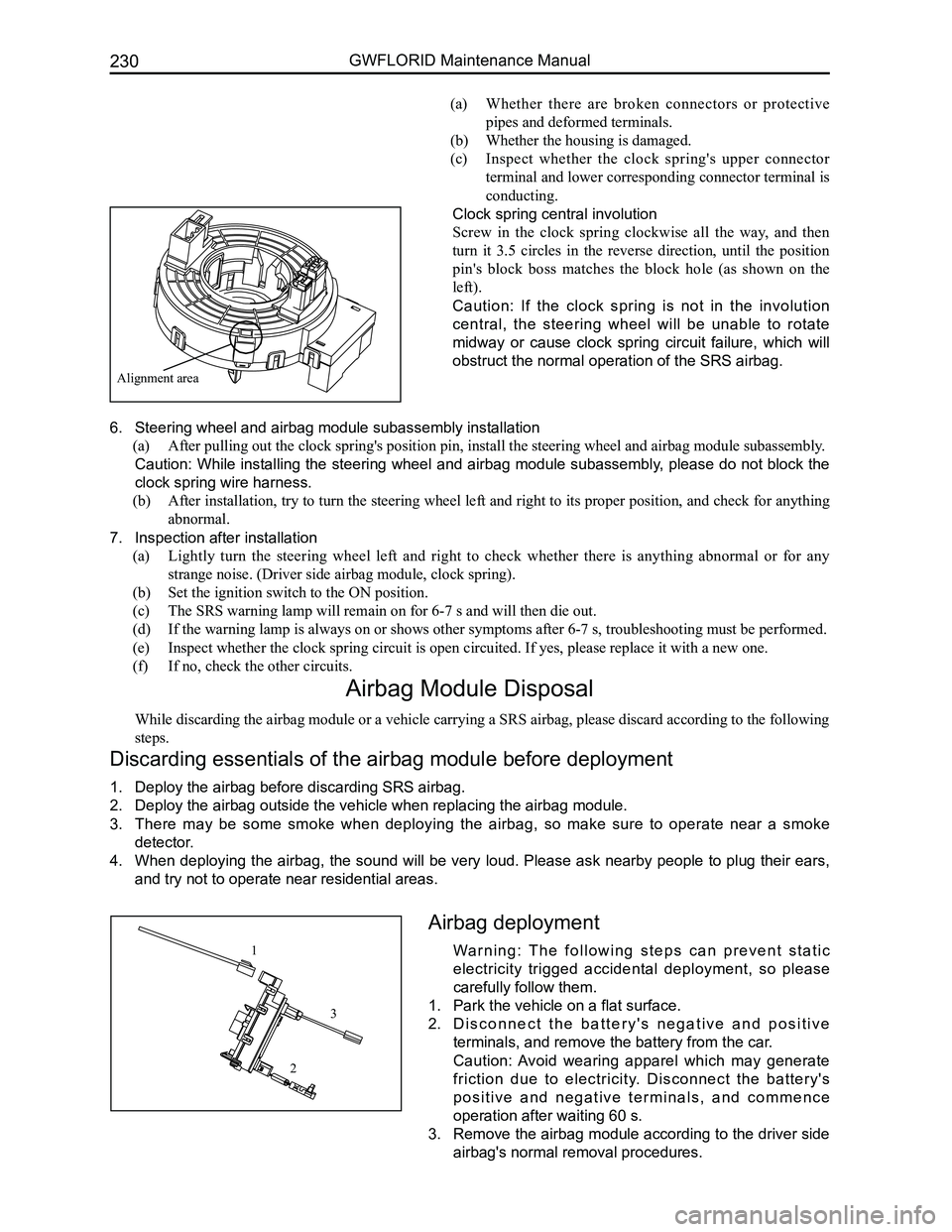
Alignment area
(a) Whether there are broken connectors or protective
pipes and deformed terminals.
(b) Whether the housing is damaged.
(c) Inspect whether the clock spring's upper connector
terminal and lower corresponding connector terminal is
conducting.
Clock spring central involution
Screw in the clock spring clockwise all the way, and then
turn it 3.5 circles in the reverse direction, until the position
pin's block boss matches the block hole (as shown on the
left).
Caution: If the clock spring is not in the involution
central, the steering wheel will be unable to rotate
midway or cause clock spring circuit failure, which will
obstruct the normal operation of the SRS airbag.
6. Steering wheel and airbag module subassembly installation
(a) After pulling out the clock spring's position pin, install the steering wheel and airbag module su\
bassembly.
Caution: While installing the steering wheel and airbag module subassembly, please do not block the
clock spring wire harness.
(b) After installation, try to turn the steering wheel left and right to its proper position, and check for anything
abnormal.
7. Inspection after installation
(a) Lightly turn the steering wheel left and right to check whether there is anything abnormal or for any
strange noise. (Driver side airbag module, clock spring).
(b) Set the ignition switch to the ON position.
(c) The SRS warning lamp will remain on for 6-7 s and will then die out.
(d) If the warning lamp is always on or shows other symptoms after 6-7 s, troubleshooting must be perf\
ormed.
(e) Inspect whether the clock spring circuit is open circuited. If yes, please replace it with a new \
one.
(f) If no, check the other circuits.
Airbag Module Disposal
While discarding the airbag module or a vehicle carrying a SRS airbag, please discard according to the following
steps.
Discarding essentials of the airbag module before deployment
1. Deploy the airbag before discarding SRS airbag.
2. Deploy the airbag outside the vehicle when replacing the airbag module.
3. There may be some smoke when deploying the airbag, so make sure to operate near a smoke
detector.
4. When deploying the airbag, the sound will be very loud. Please ask nearby people to plug their ears,
and try not to operate near residential areas.
Airbag deployment
Wa r n i n g : T h e f o l l o w i n g s t e p s c a n p r e v e n t s t a t i c
electricity trigged accidental deployment, so please
carefully follow them.
1. Park the vehicle on a flat surface.
2. D i s c o n n e c t t h e b a t t e r y ' s n e g a t i v e a n d p o s i t i v e
terminals, and remove the battery from the car.
Caution: Avoid wearing apparel which may generate
friction due to electricity. Disconnect the battery's
p o s i t i v e a n d n e g a t i v e t e r m i n a l s , a n d c o m m e n c e
operation after waiting 60 s.
3. Remove the airbag module according to the driver side
airbag's normal removal procedures.
1
2
3
Page 239 of 281
Downloaded from www.Manualslib.com manuals search engine GWFLORID Maintenance Manual232
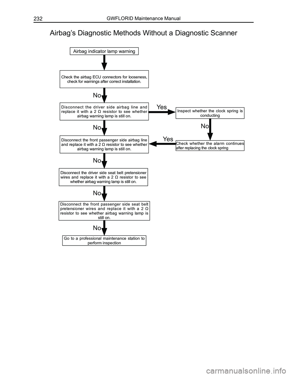
Airbag’s Diagnostic Methods Without a Diagnostic Scanner
Airbag indicator lamp warning
Check the airbag ECU connectors for looseness, check for warnings after correct installation.
Inspect whether the clock spring is conducting
Go to a professional maintenance station to perform inspection
Disconnect the front passenger side seat belt pretensioner wires and replace it with a 2 Ω resistor to see whether airbag warning lamp is still on.
Disconnect the driver side seat belt pretensioner wires and replace it with a 2 Ω resistor to see whether airbag warning lamp is still on.
Disconnect the front passenger side airbag line and replace it with a 2 Ω resistor to see whether airbag warning lamp is still on.
D i s c o n n e c t t h e d r i v e r s i d e a i r b a g l i n e a n d replace it with a 2 Ω resistor to see whether airbag warning lamp is still on.
Check whether the alarm continues after replacing the clock spring
No
No
No
No
NoNo
Yes
Yes
Page 254 of 281
Downloaded from www.Manualslib.com manuals search engine 247Vehicle Body
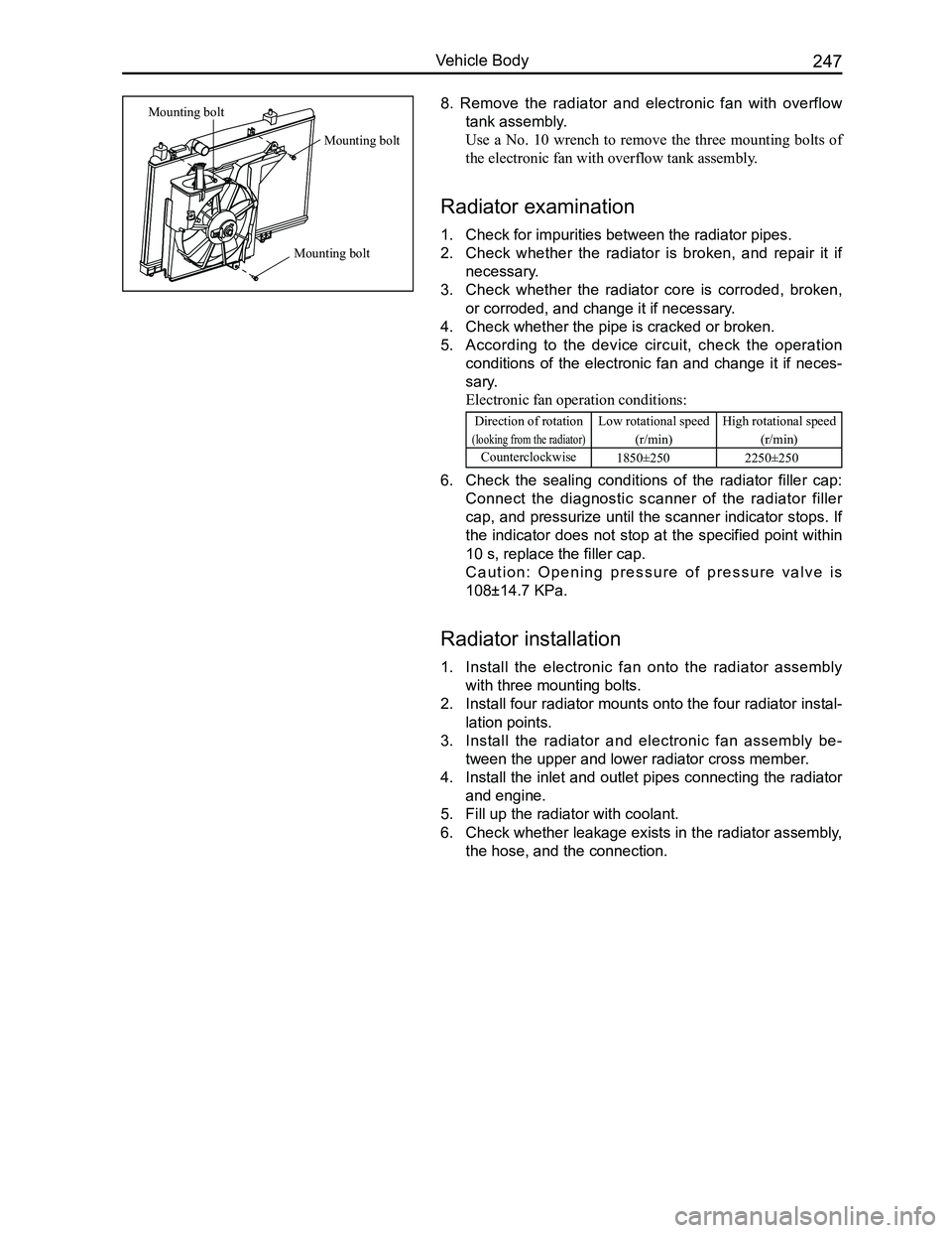
8. Remove the radiator and electronic fan with overflow
tank assembly.
Use a No. 10 wrench to remove the three mounting bolts of
the electronic fan with overflow tank assembly.
Radiator examination
1. Check for impurities between the radiator pipes.
2. Check whether the radiator is broken, and repair it if
necessary.
3. Check whether the radiator core is corroded, broken,
or corroded, and change it if necessary.
4. Check whether the pipe is cracked or broken.
5. According to the device circuit, check the operation
conditions of the electronic fan and change it if neces-
sary.
Electronic fan operation conditions:
Direction of rotation
(looking from the radiator)
Low rotational speed
(r/min)
High rotational speed
(r/min)
Counterclockwise1850±250 2250±250
6. Check the sealing conditions of the radiator filler cap:
Connect the diagnostic scanner of the radiator filler
cap, and pressurize until the scanner indicator stops. If
the indicator does not stop at the specified point within
10 s, replace the filler cap.
C a u t i o n : O p e n i n g p r e s s u r e o f p r e s s u r e v a l v e i s
108±14.7 KPa.
Radiator installation
1. Install the electronic fan onto the radiator assembly
with three mounting bolts.
2. Install four radiator mounts onto the four radiator instal-
lation points.
3. Install the radiator and electronic fan assembly be-
tween the upper and lower radiator cross member.
4. Install the inlet and outlet pipes connecting the radiator
and engine.
5. Fill up the radiator with coolant.
6. Check whether leakage exists in the radiator assembly,
the hose, and the connection.
Mounting bolt
Mounting bolt
Mounting bolt
Page 272 of 281
Downloaded from www.Manualslib.com manuals search engine 265Vehicle Body
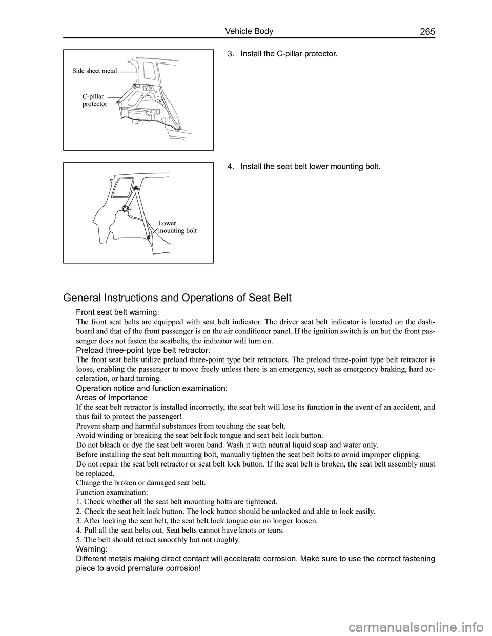
3. Install the C-pillar protector.
General Instructions and Operations of Seat Belt
Front seat belt warning:
The front seat belts are equipped with seat belt indicator. The driver seat belt indicator is located on the dash-
board and that of the front passenger is on the air conditioner panel. If the ignition switch is on but the front pas-
senger does not fasten the seatbelts, the indicator will turn on.
Preload three-point type belt retractor:
The front seat belts utilize preload three-point type belt retractors. The preload three-point type belt retractor is
loose, enabling the passenger to move freely unless there is an emergency, such as emergency braking, hard ac-
celeration, or hard turning.
Operation notice and function examination:
Areas of Importance
If the seat belt retractor is installed incorrectly, the seat belt will lose its function in the event of an accident, and
thus fail to protect the passenger!
Prevent sharp and harmful substances from touching the seat belt.
Avoid winding or breaking the seat belt lock tongue and seat belt lock bu\
tton.
Do not bleach or dye the seat belt woren band. Wash it with neutral liquid soap and water only.
Before installing the seat belt mounting bolt, manually tighten the seat\
belt bolts to avoid improper clipping.
Do not repair the seat belt retractor or seat belt lock button. If the seat belt is broken, the seat belt assembly must
be replaced.
Change the broken or damaged seat belt.
Function examination:
1. Check whether all the seat belt mounting bolts are tightened.
2. Check the seat belt lock button. The lock button should be unlocked and able to lock easily.
3. After locking the seat belt, the seat belt lock tongue can no longer loo\
sen.
4. Pull all the seat belts out. Seat belts cannot have knots or tears.
5. The belt should retract smoothly but not roughly.
Warning:
Different metals making direct contact will accelerate corrosion. Make sure to use the correct fastening
piece to avoid premature corrosion!
4. Install the seat belt lower mounting bolt.
Lower mounting bolt
Side sheet metal
C-pillar protector