Fan GREAT WALL FLORID 2008 Service Manual
[x] Cancel search | Manufacturer: GREAT WALL, Model Year: 2008, Model line: FLORID, Model: GREAT WALL FLORID 2008Pages: 281, PDF Size: 43.97 MB
Page 20 of 281
Downloaded from www.Manualslib.com manuals search engine 13Overall Parameters
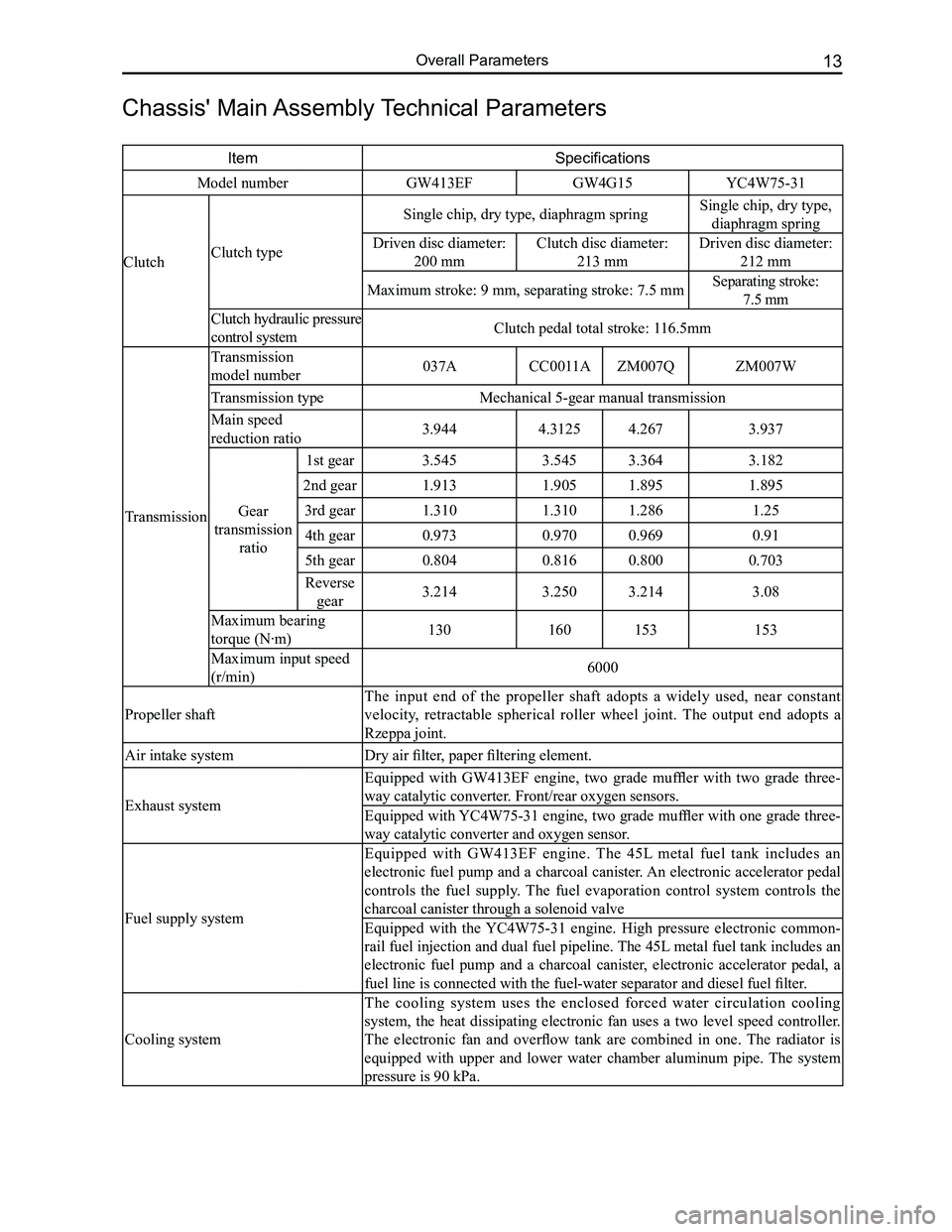
Chassis' Main Assembly Technical Parameters
ItemSpecifications
Model numberGW413EFGW4G15YC4W75-31
ClutchClutch type
Single chip, dry type, diaphragm springSingle chip, dry type,
diaphragm spring
Driven disc diameter:
200 mm
Clutch disc diameter:
213 mm
Driven disc diameter:
212 mm
Maximum stroke: 9 mm, separating stroke: 7.5 mmSeparating stroke:
7.5 mm
Clutch hydraulic pressure
control systemClutch pedal total stroke: 116.5mm
Transmission
Transmission
model number037ACC0011AZM007QZM007W
Transmission typeMechanical 5-gear manual transmission
Main speed
reduction ratio3.9444.31254.2673.937
Gear
transmission
ratio
1st gear3.5453.5453.3643.182
2nd gear1.9131.9051.8951.895
3rd gear1.3101.3101.2861.25
4th gear0.9730.9700.9690.91
5th gear0.8040.8160.8000.703
Reverse
gear3.2143.2503.2143.08
Maximum bearing
torque (N·m)130160153153
Maximum input speed
(r/min)6000
Propeller shaft
The input end of the propeller shaft adopts a widely used, near constant
velocity, retractable spherical roller wheel joint. The output end adopts a
Rzeppa joint.
Air intake systemDry air filter, paper filtering element.
Exhaust system
Equipped with GW413EF engine, two grade muffler with two grade three-
way catalytic converter. Front/rear oxygen sensors.
Equipped with YC4W75-31 engine, two grade muffler with one grade three-
way catalytic converter and oxygen sensor.
Fuel supply system
Equipped with GW413EF engine. The 45L metal fuel tank includes an
electronic fuel pump and a charcoal canister. An electronic accelerator pedal
controls the fuel supply. The fuel evaporation control system controls the
charcoal canister through a solenoid valve
Equipped with the YC4W75-31 engine. High pressure electronic common-
rail fuel injection and dual fuel pipeline. The 45L metal fuel tank includes an
electronic fuel pump and a charcoal canister, electronic accelerator pedal, a
fuel line is connected with the fuel-water separator and diesel fuel filter.
Cooling system
The cooling system uses the enclosed forced water circulation cooling
system, the heat dissipating electronic fan uses a two level speed controller.
The electronic fan and overflow tank are combined in one. The radiator is
equipped with upper and lower water chamber aluminum pipe. The system
pressure is 90 kPa.
Page 26 of 281
Downloaded from www.Manualslib.com manuals search engine 19Overall Parameters
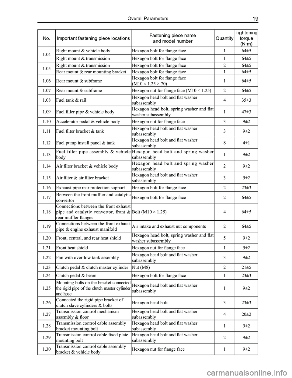
No.Important fastening piece locationsFastening piece name
and model numberQuantity
Tightening
torque
(N·m)
1.04Right mount & vehicle bodyHexagon bolt for flange face164±5
Right mount & transmissionHexagon bolt for flange face 164±5
1.05Right mount & transmissionHexagon bolt for flange face 264±5
Rear mount & rear mounting bracketHexagon bolt for flange face 164±5
1.06Rear mount & subframeHexagon bolt for flange face
(M10 × 1.25 × 70)164±5
1.07Rear mount & subframeHexagon nut for flange face (M10 × 1.25)264±5
1.08Fuel tank & railHexagon head bolt and flat washer
subassembly435±3
1.09Fuel filler pipe & vehicle bodyHexagon head bolt, spring washer and flat
washer subassembly147±3
1.10Accelerator pedal & vehicle bodyHexagon nut for flange face39±2
1.11Fuel filter bracket & tankHexagon head bolt and flat washer
subassembly39±2
1.12Fuel pump install panel & tankHexagon head bolt and flat washer
subassembly84±1
1.13Fuel filler pipe assembly & vehicle
body
H e x a g o n h e a d b o l t a n d s p r i n g w a s h e r
subassembly19±2
1.14Air filter bracket & vehicle bodyH e x a g o n h e a d b o l t a n d s p r i n g w a s h e r
subassembly29±2
1.15Air filter & air filter bracketHexagon head bolt and flat washer
subassembly39±2
1.16Exhaust pipe rear protection supportHexagon bolt for flange face223±3
1.17Between the front muffler and catalytic
convertorHexagon bolt for flange face264±5
1.18
Connections between the front exhaust
pipe and catalytic convertor, front &
rear muffler flanges
Bolt (M10 × 1.25)464±5
1.19Connections between the front exhaust
pipe & engine exhaust manifoldAir intake and exhaust nut components264±5
1.20Front, central, and rear heat shieldHexagon head bolt, spring washer and flat
washer subassembly59±2
1.21Front heat shieldHexagon nut for flange face19±2
1.22Fan with overflow tank assemblyHexagon head bolt and flat washer
subassembly39±2
1.23Clutch pedal & clutch master cylinderNut (M8)221±5
1.24Clutch pedal & beamHexagon bolt for flange face123±3
1.25
Mounting bolts on the bracket connected
the rigid pipe of the clutch master cylinder
and hose
Hexagon head bolt and flat washer
subassembly19±2
1.26Connected the rigid pipe bracket of
clutch slave cylinders & boltsHexagon head bolt323±3
1.27Transmission control mechanism
assembly & floor
Hexagon head bolt and flat washer
subassembly420±2
1.28Transmission control cable assembly
bracket mounting bolt
Hexagon head bolt and flat washer
subassembly19±2
1.29Transmission control cable fixed plate
mounting bolt
Hexagon head bolt and flat washer
subassembly29±2
1.30Transmission control cable assembly
bracket & vehicle bodyHexagon nut for flange face19±2
Page 28 of 281
Downloaded from www.Manualslib.com manuals search engine 21Overall Parameters
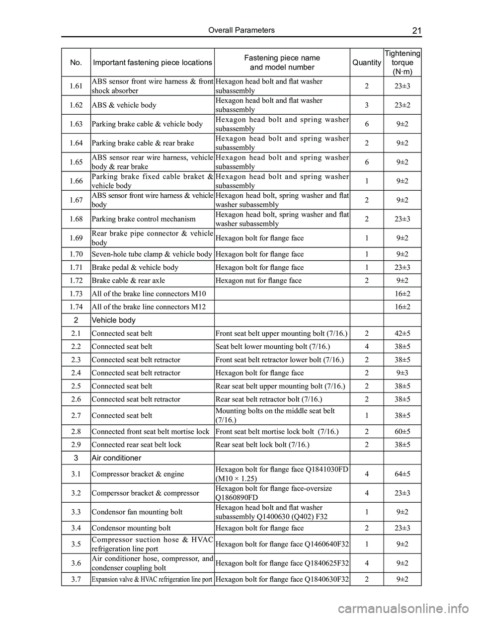
No.Important fastening piece locationsFastening piece name
and model numberQuantity
Tightening
torque
(N·m)
1.61ABS sensor front wire harness & front
shock absorber
Hexagon head bolt and flat washer
subassembly223±3
1.62ABS & vehicle body Hexagon head bolt and flat washer
subassembly323±2
1.63Parking brake cable & vehicle bodyH e x a g o n h e a d b o l t a n d s p r i n g w a s h e r
subassembly69±2
1.64Parking brake cable & rear brakeH e x a g o n h e a d b o l t a n d s p r i n g w a s h e r
subassembly29±2
1.65ABS sensor rear wire harness, vehicle
body & rear brake
H e x a g o n h e a d b o l t a n d s p r i n g w a s h e r
subassembly69±2
1.66Parking brake fixed cable braket &
vehicle body
H e x a g o n h e a d b o l t a n d s p r i n g w a s h e r
subassembly19±2
1.67ABS sensor front wire harness & vehicle
body
Hexagon head bolt, spring washer and flat
washer subassembly29±2
1.68Parking brake control mechanismHexagon head bolt, spring washer and flat
washer subassembly223±3
1.69Rear brake pipe connector & vehicle
bodyHexagon bolt for flange face19±2
1.70Seven-hole tube clamp & vehicle bodyHexagon bolt for flange face19±2
1.71Brake pedal & vehicle bodyHexagon bolt for flange face123±3
1.72Brake cable & rear axleHexagon nut for flange face29±2
1.73All of the brake line connectors M1016±2
1.74All of the brake line connectors M1216±2
2Vehicle body
2.1Connected seat belt Front seat belt upper mounting bolt (7/16.)242±5
2.2Connected seat belt Seat belt lower mounting bolt (7/16.)438±5
2.3Connected seat belt retractorFront seat belt retractor lower bolt (7/16.)238±5
2.4Connected seat belt retractorHexagon bolt for flange face29±3
2.5Connected seat belt Rear seat belt upper mounting bolt (7/16.)238±5
2.6Connected seat belt retractorRear seat belt retractor bolt (7/16.)238±5
2.7Connected seat belt Mounting bolts on the middle seat belt
(7/16.)138±5
2.8Connected front seat belt mortise lockFront seat belt mortise lock bolt (7/16.)260±5
2.9Connected rear seat belt lockRear seat belt lock bolt (7/16.)238±5
3Air conditioner
3.1Compressor bracket & engineHexagon bolt for flange face Q1841030FD
(M10 × 1.25)464±5
3.2Comperssor bracket & compressorHexagon bolt for flange face-oversize
Q1860890FD423±3
3.3Condensor fan mounting boltHexagon head bolt and flat washer
subassembly Q1400630 (Q402) F3219±2
3.4Condensor mounting boltHexagon bolt for flange face223±3
3.5Compressor suction hose & HVAC
refrigeration line portHexagon bolt for flange face Q1460640F3219±2
3.6Air conditioner hose, compressor, and
condenser coupling boltHexagon bolt for flange face Q1840625F3249±2
3.7Expansion valve & HVAC refrigeration line portHexagon bolt for flange face Q1840630F3229±2
Page 153 of 281
Downloaded from www.Manualslib.com manuals search engine GWFLORID Maintenance Manual146
Main relay
10A backup 15A backup 25A backup
Compressor relay
Reserve
Reserve
Fuel pump
Starter relay Main
relay High
beam Low
beam
Engine ECU
Fan relay High
Starter relay High beam relay Low beam relay Reserve
Horn Reserve Reserve Fan relay Low
Fan relay Low
Fan relay High
Horn relay
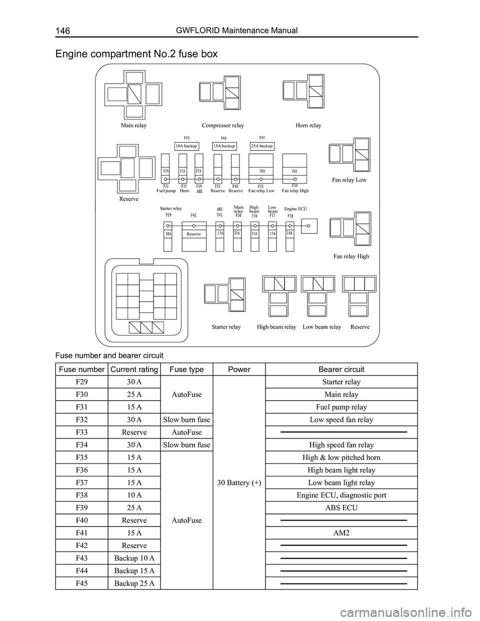
Engine compartment No.2 fuse box
Fuse number and bearer circuit
Fuse numberCurrent ratingFuse typePowerBearer circuit
F2930 A
AutoFuse
30 Battery (+)
Starter relay
F3025 AMain relay
F3115 AFuel pump relay
F3230 ASlow burn fuse Low speed fan relay
F33ReserveAutoFuse
F3430 ASlow burn fuse High speed fan relay
F3515 A
AutoFuse
High & low pitched horn
F3615 AHigh beam light relay
F3715 ALow beam light relay
F3810 AEngine ECU, diagnostic port
F3925 AABS ECU
F40Reserve
F4115 AAM2
F42Reserve
F43Backup 10 A
F44Backup 15 A
F45Backup 25 A
Page 159 of 281
Downloaded from www.Manualslib.com manuals search engine GWFLORID Maintenance Manual152
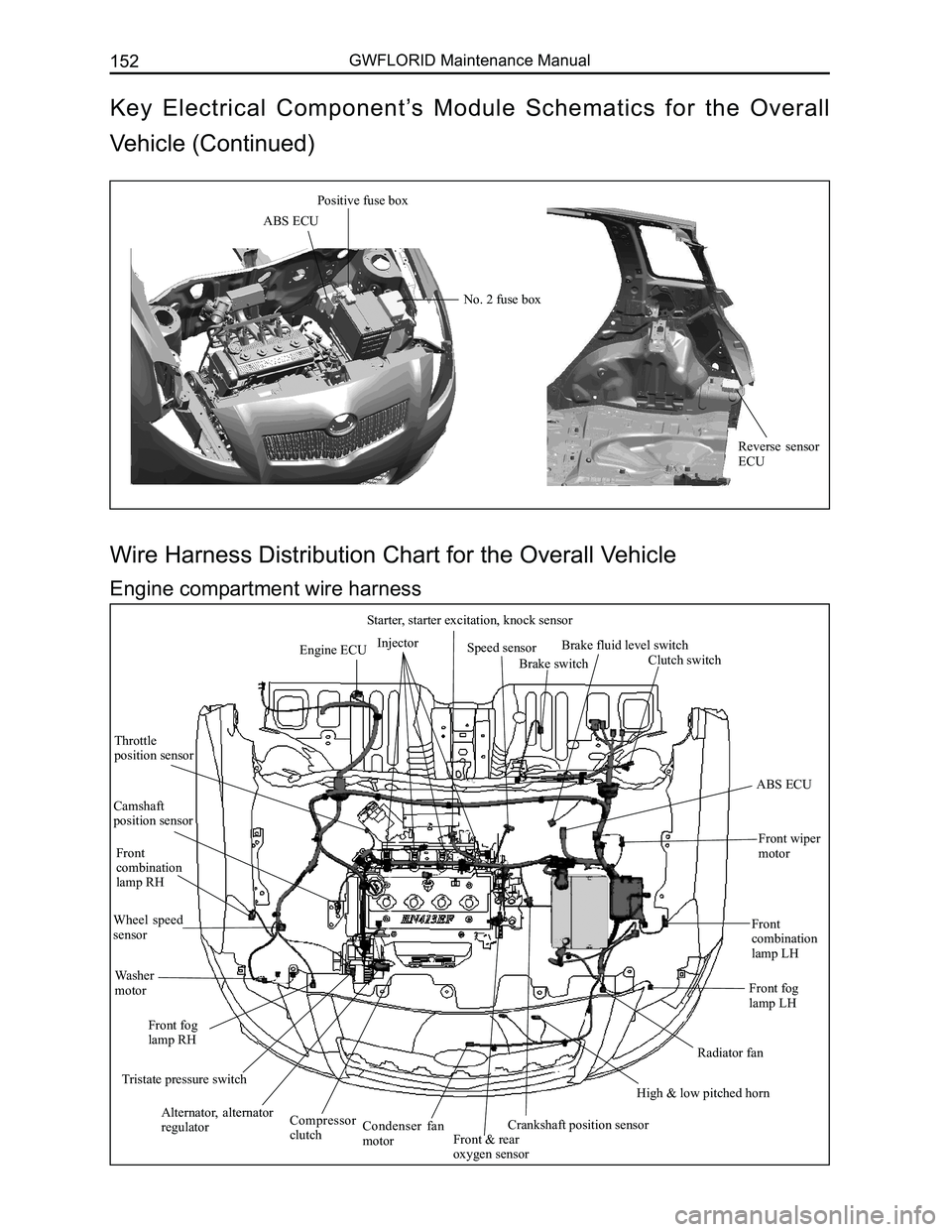
Engine ECUInjector
Starter, starter excitation, knock sensor
Speed sensor
Brake switch
Brake fluid level switch
Clutch switch
ABS ECU
Front wiper
motor
Front combination lamp LH
Front fog lamp LH
Radiator fan
High & low pitched horn
Crankshaft position sensorFront & rear oxygen sensor
Condenser fan motor
Compressor clutch
Alternator, alternator regulator
Tristate pressure switch
Front fog lamp RH
Washer motor
Wheel speed sensor
Front combination lamp RH
Camshaft position sensor
Throttle position sensor
Wire Harness Distribution Chart for the Overall Vehicle
Engine compartment wire harness
ABS ECU
Positive fuse box
No. 2 fuse box
Reverse sensor ECU
Key Electrical Component’s Module Schematics for the Overall
Vehicle (Continued)
Page 162 of 281
Downloaded from www.Manualslib.com manuals search engine 155Vehicle Body Electronic System
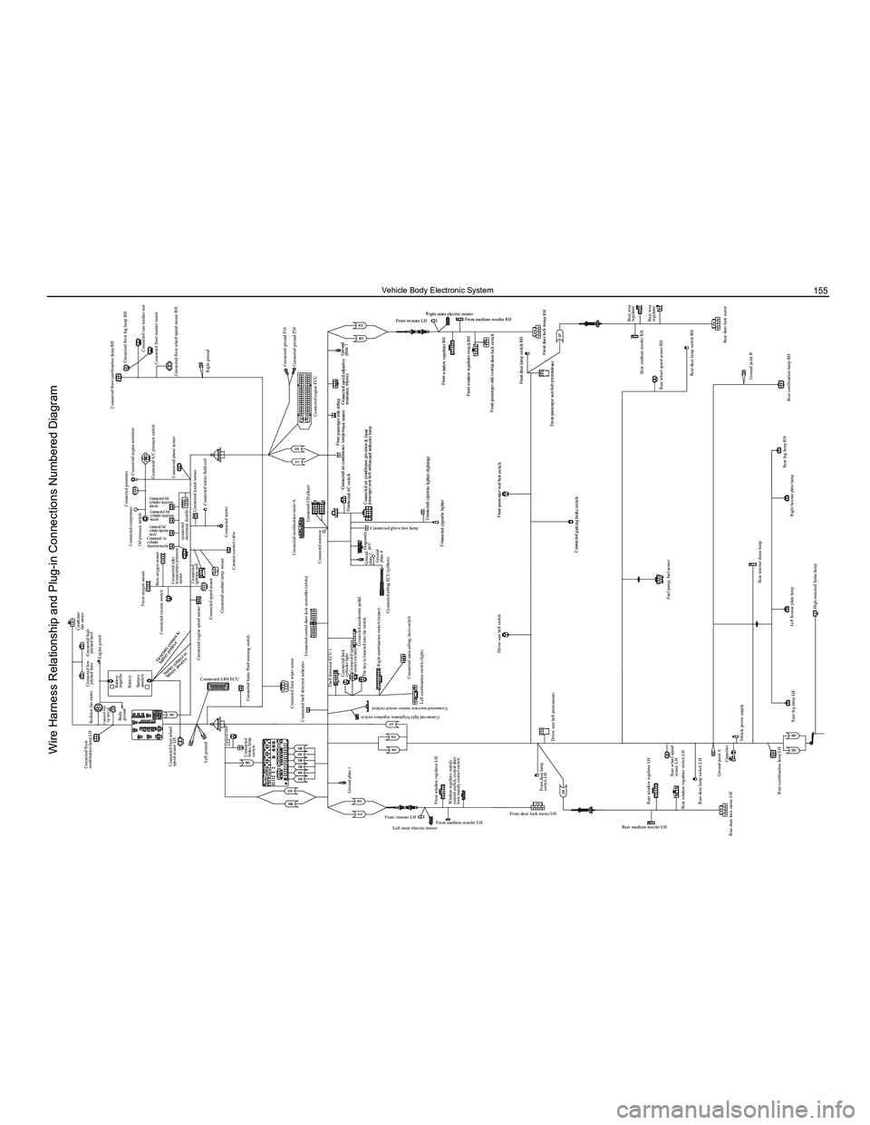
Condenser fan motor
Connected compressor
Oil pressure switch
Front oxygen sensor
Connected reverse switch
Connected engine speed sensor Connected
ignition coil
Connected speed sensor Connected coolant temp. sensor
Canister control valve
Connected combination meter A
Connected antenna
Diagnostic port
Connected AC switch Connected air conditioner temperature sensor
Front passenger side airbag
Connected speed adjustive resistance, blower
Front window regulator RH
Front window regulator switch RH
Front medium woofer RH
Front tweeter LH Right outer electric mirror
Front passenger side central door lock switch
Front door lamp switch RH
Front passenger seat belt pretensioner Front door lock motor RH
Ground
plate 3
Connected cigarette lighter (lighting)
Connected cigarette lighter
Front passenger seat belt switch
Connected parking brake switch Connected air conditioner governor & front
passenger seat belt unfastened indicator lamp
Connected CD player
Connected engine ECUConnected ground P1#
Connected ground P2#
Connected starter
Connected knock sensor
Connected starter field coil
Connected inlet
temperature pressure
sensor
connected
electronic throttle
Rear oxygen sensor
Connected 4th
cylinder injection
nozzle
Connected 3rd
cylinder injection
nozzle
Connected 2nd
cylinder injection
nozzle
Connected 1st
cylinder
injection nozzle
Connected generator
Connected engine armature Connected front combination lamp RH
Connected front fog lamp RH
Connected rear washer motor
Connected front washer motor
Connected front wheel speed sensor RH
Right ground
Connected A/C pressure switch
Connected phase sensor
Connected low
pitched horn
Connected front
combination lamp LH
Rediator fan motor
Connected front
fog lamp LH
Connected high pitched horn
Battery
negative
Body
ground
Battery
Left ground Connected
brake lamp
switch Connected brake fluid warning switch
Connected theft deterrent indicator Theft deterrent ECU 1Connected lock
cylinder lightConnected ignition
switch (white)
The key is inserted into the switch
Right combination switch (wiper) Connected airbag ECU (yellow)Ground
plate 2
Ground
plate 4
Connected accelerator pedal
Ground plate 1
Left outer electric mirror
Front medium woofer LH Front door lock motor LH
Rear medium woofer LH
Rear window regulator switch LH
Rear door lock motor LH Rear door lamp switch LH
Ground point ACapacitor
Vehicle power supply
Rear fog lamp LH Left license plate lamp
High mounted brake lamp
Ground point Trunk opener switch
Trunk motorRear wiper motor
Rear windshield defroster “-”
Trunk lamp switch Right license plate lamp
Rear fog lamp RH
Rear combination lamp RHRear wheel speed sensor RH
Rear window
regulator RH
Rear window
regulator switch RH
Rear door lock motor RH
Rear door lamp switch RH Rear medium woofer RH
Ground point B
Rear combination lamp LH
Rear windshield defroster “+”
Rear wheel speed
sensor LH
Rear window regulator LH
Fuel pump, fuel sensor
Rear interior dome lamp
Front door lamp
switch LH
Driver seat belt pretensioner Driver seat belt switch
Front tweeter LH
Connected light brightness regulator switch
Connected rearview mirror switch (white)
Connected glove box lamp
Front window regulator LH Left combination switch (light)
Connected main airbag, horn switch
Window regulator mainly
control switch, central door
lock mainly control switch Connected central door lock controller (white)
Connected front wiper motor
Connected clutch
switch
Connected ABS ECUBattery
positive
Connected front wheel
speed sensor LH Engine groud
Starter connect to
battery positive
Generator connect to
battery positive
Wire Harness Relationship and Plug-in Connections Numbered Diagram
Page 180 of 281
Downloaded from www.Manualslib.com manuals search engine 173Vehicle Body Electronic System
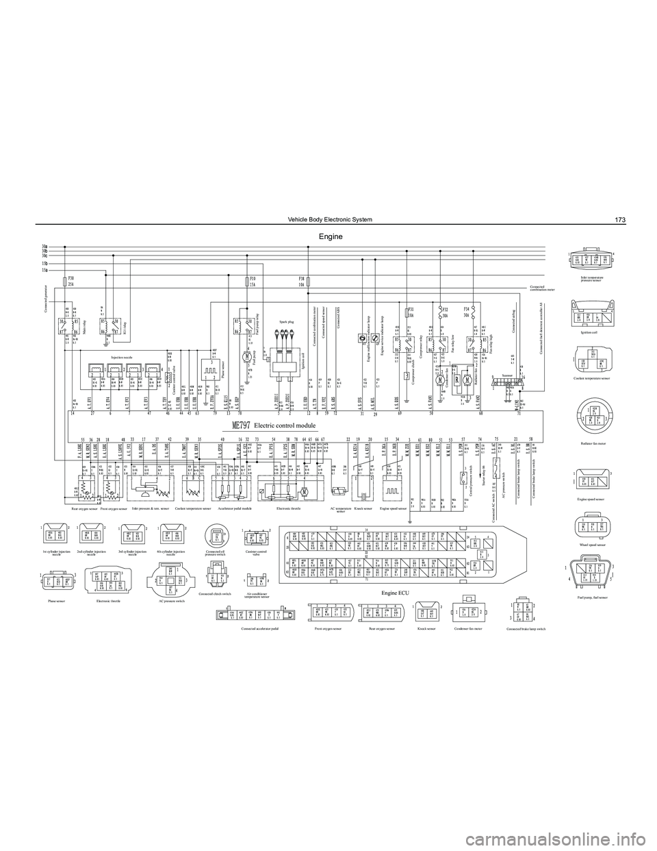
Engine
Connected generator
Canister control valve
Rear oxygen sensor
1st cylinder injection nozzle
Phase sensor Electronic throttle AC pressure switchConnected clutch switch
Air conditioner
temperature sensor
Connected accelerator pedal Front oxygen sensorRear oxygen sensorKnock sensorCondenser fan motor
Connected brake lamp switch
Engine ECU
2nd cylinder injection
nozzle 3rd cylinder injection
nozzle 4th cylinder injection
nozzle Connected oil
pressure switch Canister control
valve
Front oxygen sensor
Inlet pressure & tem. sensor
Coolant temperature sensor Accelerator pedal module Electronic throttle AC temperature
sensor Knock sensor
Engine speed sensor
Phase sensor
Fuel pump relay
Connected combination meter Connected speed sensor
Engine malfunction indicator lamp Engine service indicator lamp
Compressor relay
Compressor clutch
Central pressure switch Starter relay 86
Connected AC switch AC pressure switch
Connected brake lamp switch
Connected brake lamp switch Condenser fan
Rediator fan Fan relay lowScanner
Fan relay high
Connected airbag
Connected theft deterrent controller A8
Connected
combination meter
Ignition coil
Coolant temperature sensor
Rediator fan motor
Engine speed sensor Wheel speed sensor
Fuel pump, fuel sensor Inlet temperature
pressure sensor
Connected ABS
Spark plug
Fuel pump
Electric control module
Ignition coil
Main relay
Injection nozzle
IG1 relay
Page 211 of 281
Downloaded from www.Manualslib.com manuals search engine GWFLORID Maintenance Manual204
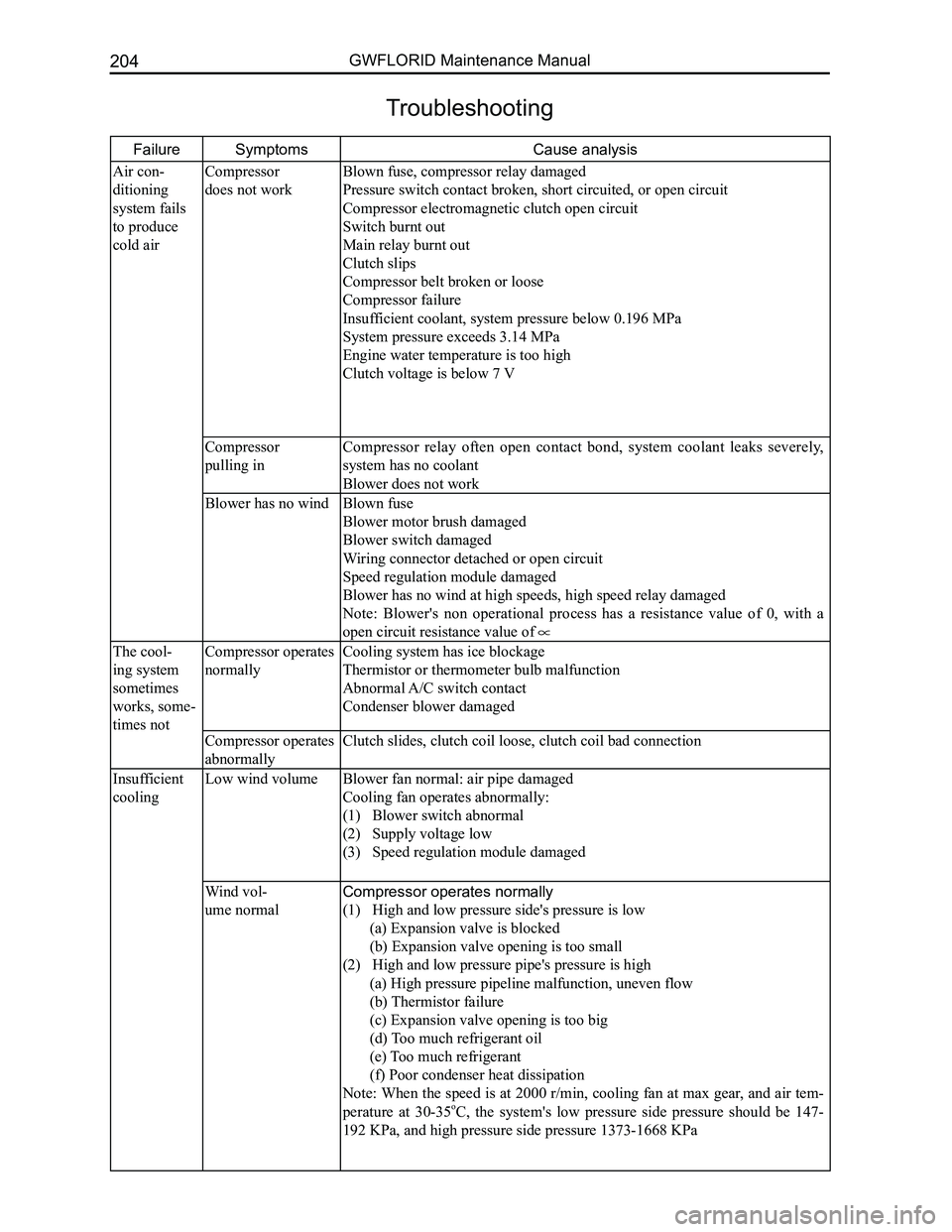
FailureSymptoms Cause analysis
Air con-
ditioning
system fails
to produce
cold air
Compressor
does not work
Blown fuse, compressor relay damaged
Pressure switch contact broken, short circuited, or open circuit
Compressor electromagnetic clutch open circuit
Switch burnt out
Main relay burnt out
Clutch slips
Compressor belt broken or loose
Compressor failure
Insufficient coolant, system pressure below 0.196 MPa
System pressure exceeds 3.14 MPa
Engine water temperature is too high
Clutch voltage is below 7 V
Compressor
pulling in
Compressor relay often open contact bond, system coolant leaks severely,
system has no coolant
Blower does not work
Blower has no windBlown fuse
Blower motor brush damaged
Blower switch damaged
Wiring connector detached or open circuit
Speed regulation module damaged
Blower has no wind at high speeds, high speed relay damaged
Note: Blower's non operational process has a resistance value of 0, with a
open circuit resistance value of
The cool-
ing system
sometimes
works, some-
times not
Compressor operates
normally
Cooling system has ice blockage
Thermistor or thermometer bulb malfunction
Abnormal A/C switch contact
Condenser blower damaged
Compressor operates
abnormally
Clutch slides, clutch coil loose, clutch coil bad connection
Insufficient
cooling
Low wind volume
Blower fan normal: air pipe damaged
Cooling fan operates abnormally:
(1) Blower switch abnormal
(2) Supply voltage low
(3) Speed regulation module damaged
Wind vol-
ume normal
Compressor operates normally
(1) High and low pressure side's pressure is low
(a) Expansion valve is blocked
(b) Expansion valve opening is too small
(2) High and low pressure pipe's pressure is high
(a) High pressure pipeline malfunction, uneven flow
(b) Thermistor failure
(c) Expansion valve opening is too big
(d) Too much refrigerant oil
(e) Too much refrigerant
(f) Poor condenser heat dissipation
Note: When the speed is at 2000 r/min, cooling fan at max gear, and air tem-
perature at 30-35oC, the system's low pressure side pressure should be 147-
192 KPa, and high pressure side pressure 1373-1668 KPa
Troubleshooting
Page 213 of 281
Downloaded from www.Manualslib.com manuals search engine GWFLORID Maintenance Manual206
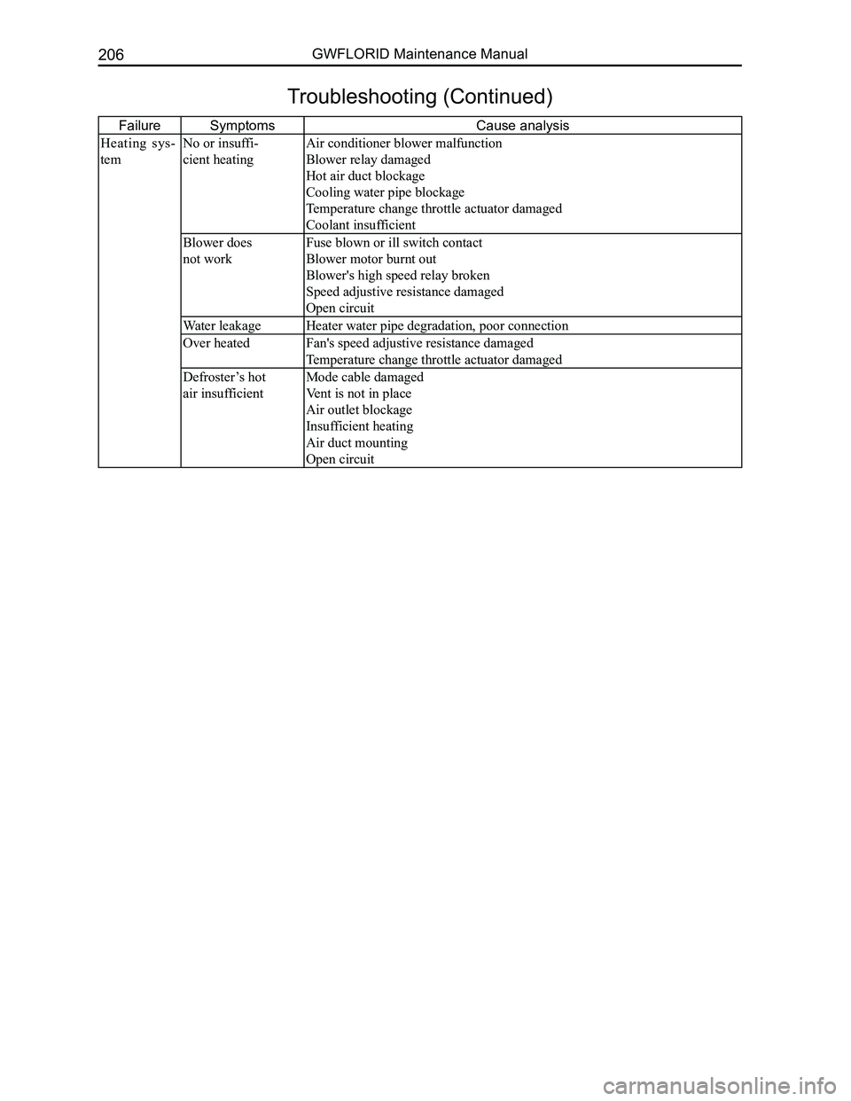
FailureSymptoms Cause analysis
Heating sys-
tem
No or insuffi-
cient heating
Air conditioner blower malfunction
Blower relay damaged
Hot air duct blockage
Cooling water pipe blockage
Temperature change throttle actuator damaged
Coolant insufficient
Blower does
not work
Fuse blown or ill switch contact
Blower motor burnt out
Blower's high speed relay broken
Speed adjustive resistance damaged
Open circuit
Water leakageHeater water pipe degradation, poor connection
Over heatedFan's speed adjustive resistance damaged
Temperature change throttle actuator damaged
Defroster’s hot
air insufficient
Mode cable damaged
Vent is not in place
Air outlet blockage
Insufficient heating
Air duct mounting
Open circuit
Troubleshooting (Continued)
Page 214 of 281
Downloaded from www.Manualslib.com manuals search engine 207Air Conditioning System
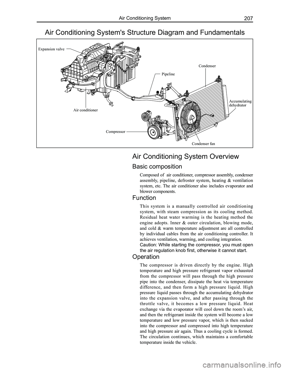
Air Conditioning System's Structure Diagram and Fundamentals
Air Conditioning System Overview
Basic composition
Composed of air conditioner, compressor assembly, condenser
assembly, pipeline, defroster system, heating & ventilation
system, etc. The air conditioner also includes evaporator and
blower components.
Function
This system is a manually controlled air conditioning
system, with steam compression as its cooling method.
Residual heat water warming is the heating method the
engine adopts. Inner & outer circulation, blowing mode,
and cold & warm temperature adjustment are all controlled
by individual cables from the air conditioning controller. It
achieves ventilation, warming, and cooling integration.
Caution: While starting the compressor, you must open
the air regulation knob first, otherwise it cannot start.
Operation
The compressor is driven directly by the engine. High
temperature and high pressure refrigerant vapor exhausted
from the compressor will pass through the high pressure
pipe into the condenser, dissipate the heat via temperature
difference, and then form a high pressure liquid. High
pressure liquid passes through the accumulating dehydrator
into the expansion valve, and after passing through the
throttle valve, it becomes a low pressure liquid. Heat
exchange via the evaporator will cool down the room’s air,
and then the refrigerant inside the system will become a low
temperature and low pressure vapor, which is then sucked
into the compressor and compressed into high temperature
and high pressure air again. Thus a cooling cycle is formed.
The circulation continues, which maintains a comfortable
temperature inside the vehicle.
Expansion valve
Compressor
Condenser fan
Condenser
Pipeline
Air conditioner
Accumulating dehydrator