change wheel GREAT WALL FLORID 2008 Service Manual
[x] Cancel search | Manufacturer: GREAT WALL, Model Year: 2008, Model line: FLORID, Model: GREAT WALL FLORID 2008Pages: 281, PDF Size: 43.97 MB
Page 97 of 281
Downloaded from www.Manualslib.com manuals search engine GWFLORID Maintenance Manual90
Vehicle road test methods
1. Drive the vehicle and find out if the swaying is coming from the front tires or the back tires. Then replace the
identified problem tire with a good tire (one that has been tested on t\
he same model of vehicle).
2. If unable to determine the problem tire, replace the rear wheels. Continue with the road test. If the driving
condition obviously changes, replace the original tires, and only switch one at a time until the problem tire is
identified.
3. If no obvious improvement, replace all four tires with good tires, and then replace the original tires one by
one following the steps mentioned above.
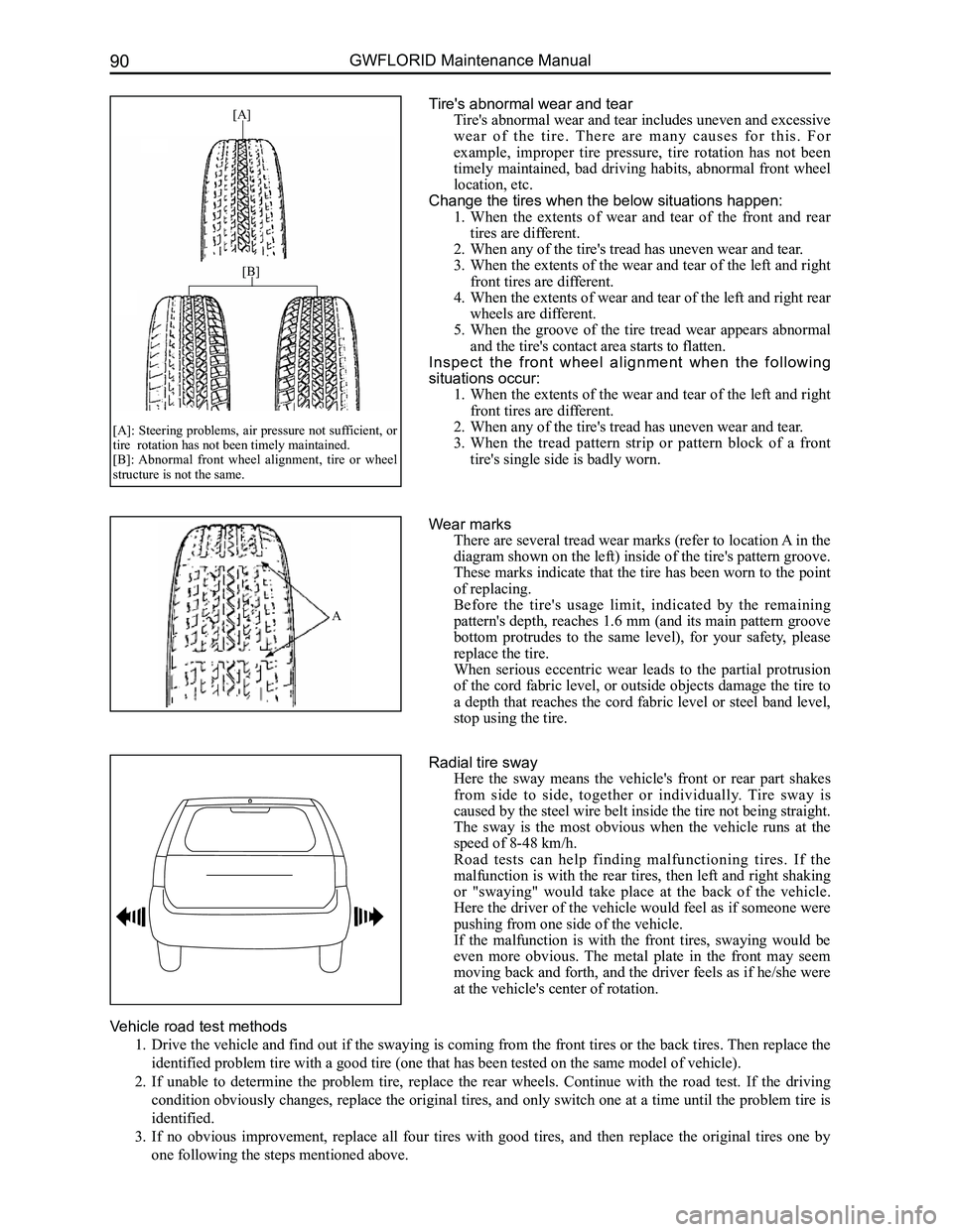
Tire's abnormal wear and tear
Tire's abnormal wear and tear includes uneven and excessive
w e a r o f t h e t i r e . T h e r e a r e m a n y c a u s e s f o r t h i s . F o r
example, improper tire pressure, tire rotation has not been
timely maintained, bad driving habits, abnormal front wheel
location, etc.
Change the tires when the below situations happen:
1. When the extents of wear and tear of the front and rear
tires are different.
2. When any of the tire's tread has uneven wear and tear.
3. When the extents of the wear and tear of the left and right
front tires are different.
4. When the extents of wear and tear of the left and right rear
wheels are different.
5. When the groove of the tire tread wear appears abnormal
and the tire's contact area starts to flatten.
Inspect the front wheel alignment when the following
situations occur:
1. When the extents of the wear and tear of the left and right
front tires are different.
2. When any of the tire's tread has uneven wear and tear.
3. When the tread pattern strip or pattern block of a front
tire's single side is badly worn.
[A]
[B]
[A]: Steering problems, air pressure not sufficient, or tire rotation has not been timely maintained. [B]: Abnormal front wheel alignment, tire or wheel structure is not the same.
Radial tire sway
Here the sway means the vehicle's front or rear part shakes
from side to side, together or individually. Tire sway is
caused by the steel wire belt inside the tire not being straight.
The sway is the most obvious when the vehicle runs at the
speed of 8-48 km/h.
Road tests can help finding malfunctioning tires. If the
malfunction is with the rear tires, then left and right shaking
or "swaying" would take place at the back of the vehicle.
Here the driver of the vehicle would feel as if someone were
pushing from one side of the vehicle.
If the malfunction is with the front tires, swaying would be
even more obvious. The metal plate in the front may seem
moving back and forth, and the driver feels as if he/she were
at the vehicle's center of rotation.
Wear marks
There are several tread wear marks (refer to location A in the
diagram shown on the left) inside of the tire's pattern groove.
These marks indicate that the tire has been worn to the point
of replacing.
Before the tire's usage limit, indicated by the remaining
pattern's depth, reaches 1.6 mm (and its main pattern groove
bottom protrudes to the same level), for your safety, please
replace the tire.
When serious eccentric wear leads to the partial protrusion
of the cord fabric level, or outside objects damage the tire to
a depth that reaches the cord fabric level or steel band level,
stop using the tire.
A
Page 99 of 281
Downloaded from www.Manualslib.com manuals search engine GWFLORID Maintenance Manual92
Wheel
General tire balancing procedures
Clean out the accumulated dirt and debris from the inside of the rim.
Warning:
The gravel on the tread must be eliminated to avoid flying out and injuring the operator when
undergoing rotational balancing. This is also a good way to acquire better balance. First thoroughly
inspect the tire's damaged condition, then according to the balancing device manufacture's
recommendations, carry out the balancing operation.
Off-vehicle balancing
Most off-vehicle balancers are more accurate and convenient than on-vehicle rotational balancers. They are
also able to perform dynamic (two sided) balancing. Although it does not correct drum brake and brake disc
imbalance like on-vehicle balancing, it achieves the same effect based on its accuracy.
On-vehicle balancing
On-vehicle balancing is different based on equipment and tool manufacturer. Therefore, when performing
balancing operations, be sure to comply to each manufacturer's operating\
instructions.
Warning: Control the wheel rotation speed to make sure the speedometer stays within 55 km/h.
This restriction is necessary because when a driven wheel slides while the other one stays still, the
speedometer will display only half of the actual wheel speed. When a wheel is sliding, be extremely
careful, because sliding wheels can reach very high speeds. This may lead to the tire rubber peeling
or differential damage, which may cause serious personal injury, or damage to the vehicle.
Tire installation and removal
• Install or remove tires with a tire changer. When operating machinery, make sure to comply to the machine
manufacturers operation manual. Please do not change tires merely with manual hand tools or tire installation
crowbars. This will damage the tire chafer or the vehicle wheel's rim.
• Use a wire brush or coarse steel wool to clean off grease and old rubber, as well as light rust or corrosion from
the rim tire bead's tire chafer seat. Before tire installation or removal, first use the indicated tire lubricant to
thoroughly lube the tire chafer portions one time.
• After installing the tire, inflate it to the specified pressure and make\
sure the tire bead is properly seated.
Warning: Do not over-inflate the tire. If the tire bead severally expands and exceeds the safety limit,
it may burst and cause serious personal injury. While inflating, do not exceed the specified pressure.
If the specified pressure does not allow the tire bead to sit properly, deflate the tire, re-lubricate, and
then re-inflate.
Spare tire usage
• Spare tire standard inflation pressure: 420 kPa.
• Spare tire pressure measurements should be taken under normal temperatur\
e conditions.
• After inflating the spare tire, soapy water should be used to check if the air nozzles core is leaking air, then
lock on the air nozzle cap.
• The spare tire should always be kept in a useable state. Check the air p\
ressure at least once a month.
• When the spare tire's working limit, indicated by the remaining pattern's depth, reaches 1.6 mm (and its pat-
tern groove bottom protrudes to the same level), for your safety, please stop using the spare tire.
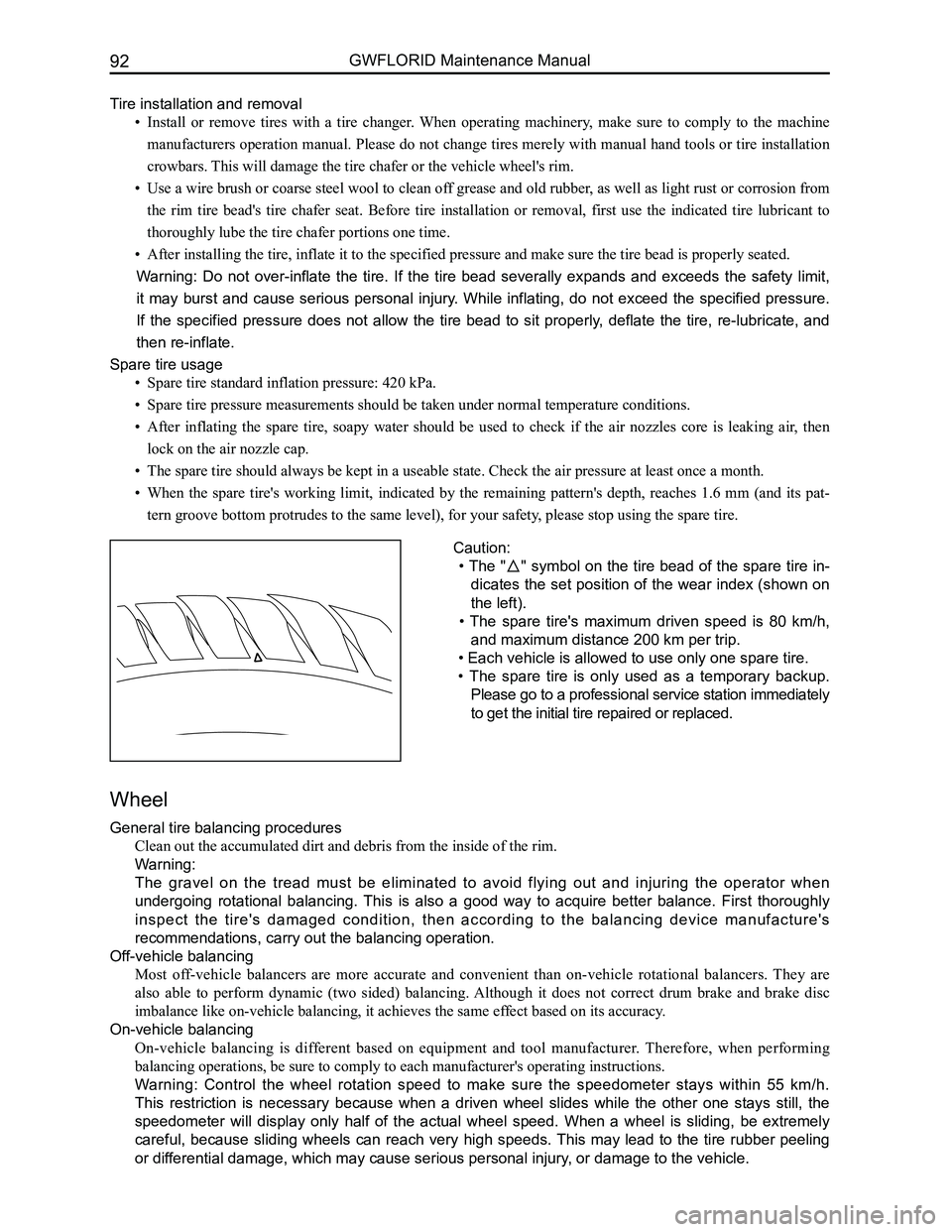
Caution:
• The "" symbol on the tire bead of the spare tire in-
dicates the set position of the wear index (shown on
the left).
• The spare tire's maximum driven speed is 80 km/h,
and maximum distance 200 km per trip.
• Each vehicle is allowed to use only one spare tire.
• The spare tire is only used as a temporary backup.
Please go to a professional service station immediately
to get the initial tire repaired or replaced.
Page 103 of 281
Downloaded from www.Manualslib.com manuals search engine GWFLORID Maintenance Manual96
Brake System Maintenance
Brake fluid inspection and replacement
Brake fluid directly influences the brake performance and the operating conditions and use life of the brake
system components. Brake fluid has very strong hygroscopic properties, and thus absorbs water easily,
which will then deteriorate the metal and rubber pieces. Polluted and deteriorated brake fluid or its mixture
would cause the brake fluid to boil and gasify, hence reduces braking efficiency. Therefore, pay attention to
the items below when filling or changing the brake fluid:
1. Containers used to hold brake fluid must be tightly closed and sealed
2. Brake fluid is poisonous and damaging to the paint. Hence if it gets on the vehicle surface, rub it
off at once
3. If water or other contaminates found in the brake fluid, and the brake master cylinder's piston seal
has been broken, then the brake fluid and all the rubber pieces inside the brake system including
the brake hose must be replaced
4. The correct brake fluid level in the reservoir must be between MAX and MIN. After the vehicle has
been driven for over 1000 km, check the brake fluid level in the reservoir. If the brake fluid level is
not up to regulation, more brake fluid should be added to the reservoir \
until it reaches MAX.
Hydraulic component inspection and system flushing
1. If the oil-based solvent gets into the hydraulic system, flush the whole system and change all of
the rubber pieces
2. Clean your hands before installing new rubber pieces or other components
3. Do not use regular solvents (kerosene, gas, etc.) when inspecting or cleaning hydraulic
components, instead use absorbing alcohol or brake fluid
4. After inspecting the components, drain the brake fluid from the system. Use new brake fluid to
flush the system. Afterwards, add new brake fluid to perform hydraulic system exhaust
5. Flushing completion sign: When the brake fluid flowing out of the dump valve is clear from any
contaminate.
Hydraulic pressure system drainage
If the brake fluid inside the whole hydraulic pressure system needs to be emptied, open all the bleed screws
with each connected to a hose, as to allow the brake fluid to flow into a container. Step on the pedal slowly
until only air flows out. During the whole procedure, make sure all the \
valves are open.
Hydraulic pressure system air bleeding
The hydraulic brake system must work under a vacuum environment. The air will cause spongy brake or
overall brake failure when it flows into the hydraulic system. It is extremely necessary to bleed system air
when performing any operation on the brake system or if any air inside t\
he brake system is suspected.
1. Air bleeding sequence
If air inside the brake master cylinder is suspected, first perform air bleeding.
(a) If numerous valves are equipped, air bleed each valve
(b) Another sequence principle is: Air bleed from the wheel brake furthest away from the master cylinder.
The air bleeding sequence for the LHD modules is: rear right wheel - left rear wheel - front right wheel
- front left wheel, Right rudder vehicles: rear right wheel - left rear wheel - front left wheel - front right
wheel.
2. Air bleeding method
(1) Manual air bleeding
Use the brake pedal or pump as the air bleeding power source. When the air bleed screws are open, vent the
brake fluid containing the bubbles from the system. Usually this is simultaneously done by two people. One
steps on the brake pedal and the other operates the air bleed screws. Important points to take note of when
performing the operation:
(a) Place the ignition switch to the off position and step on the pedal repeatedly to remove the
vacuum pressure or hydraulic pressure.
(b) Before and after air bleeding, add clean brake fluid into the master cylinder until it reaches
the correct (stated) level.
(c) Check the fluid level frequently to make sure that more than half of the reservoir's capacity is
available.
(d) Bleed screws should only be opened when the pedal is pressed down, and closed before the
pedal is loosened. Meanwhile, check if the vented brake fluid has bubble\
s inside.
Page 116 of 281
Downloaded from www.Manualslib.com manuals search engine 109Brake System
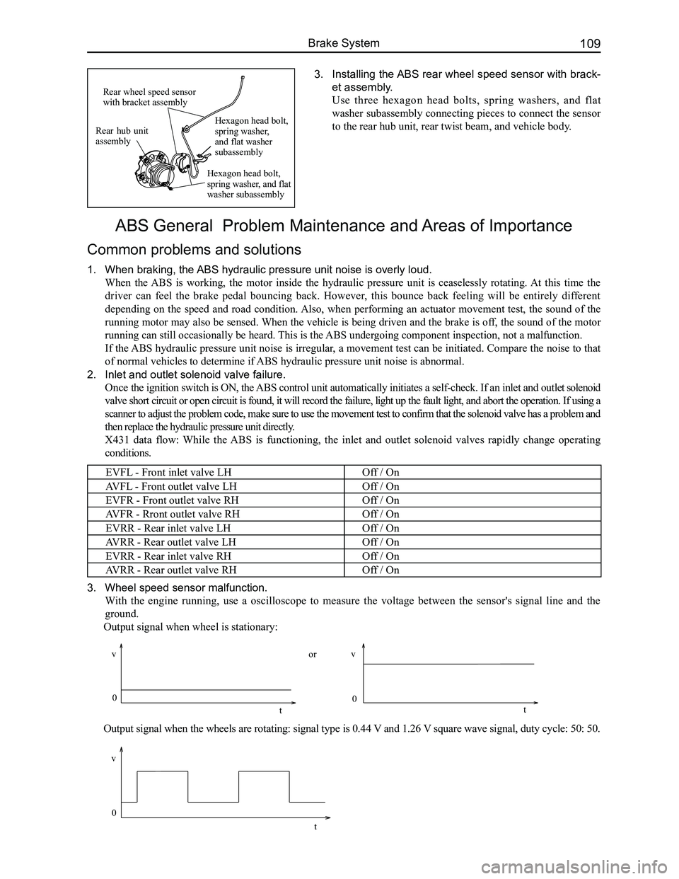
3. Installing the ABS rear wheel speed sensor with brack-
et assembly.
Use three hexagon head bolts, spring washers, and flat
washer subassembly connecting pieces to connect the sensor
to the rear hub unit, rear twist beam, and vehicle body.
ABS General Problem Maintenance and Areas of Importance
Common problems and solutions
1. When braking, the ABS hydraulic pressure unit noise is overly loud.
When the ABS is working, the motor inside the hydraulic pressure unit is ceaselessly rotating. At this time the
driver can feel the brake pedal bouncing back. However, this bounce back feeling will be entirely different
depending on the speed and road condition. Also, when performing an actuator movement test, the sound of the
running motor may also be sensed. When the vehicle is being driven and the brake is off, the sound of the motor
running can still occasionally be heard. This is the ABS undergoing component inspection, not a malfunction.
If the ABS hydraulic pressure unit noise is irregular, a movement test can be initiated. Compare the noise to that
of normal vehicles to determine if ABS hydraulic pressure unit noise is abnormal.
2. Inlet and outlet solenoid valve failure.
Once the ignition switch is ON, the ABS control unit automatically initiates a self-check. If an inlet and outlet solenoid
valve short circuit or open circuit is found, it will record the failure, light up the fault light, and abort the operation. If using a
scanner to adjust the problem code, make sure to use the movement test t\
o confirm that the solenoid valve has a problem and
then replace the hydraulic pressure unit directly.
X431 data flow: While the ABS is functioning, the inlet and outlet solenoid valves rapidly change operating
conditions.
EVFL - Front inlet valve LHOff / On
AVFL - Front outlet valve LHOff / On
EVFR - Front outlet valve RHOff / On
AVFR - Rront outlet valve RHOff / On
EVRR - Rear inlet valve LHOff / On
AVRR - Rear outlet valve LHOff / On
EVRR - Rear inlet valve RHOff / On
AVRR - Rear outlet valve RHOff / On
3. Wheel speed sensor malfunction.
With the engine running, use a oscilloscope to measure the voltage between the sensor's signal line and the
ground.
Output signal when wheel is stationary:
Output signal when the wheels are rotating: signal type is 0.44 V and 1.26 V square wave signal, duty cycle: 50: 50.
Rear hub unit assembly
Rear wheel speed sensor with bracket assembly
Hexagon head bolt, spring washer, and flat washer subassembly
Hexagon head bolt, spring washer, and flat washer subassembly
0
v
t
vv
0 0
tt
or
Page 119 of 281
Downloaded from www.Manualslib.com manuals search engine GWFLORID Maintenance Manual112
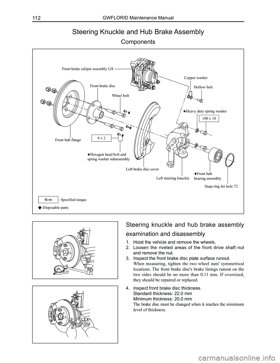
Steering Knuckle and Hub Brake Assembly
Components
Disposable parts
Steering knuckle and hub brake assembly
examination and disassembly
1. Hoist the vehicle and remove the wheels.
2. Loosen the riveted areas of the front drive shaft nut
and remove the nut.
3. Inspect the front brake disc plate surface runout.
When measuring, tighten the two wheel nuts' symmetrical
locations. The front brake disc's brake linings runout on the
two sides should be no more than 0.11 mm. If oversized,
they should be repaired or replaced.
4. Inspect front brake disc thickness.
Standard thickness: 22.0 mm
Minimum thickness: 20.0 mm
The brake disc must be changed when it reaches the minimum
level of thickness.
Front brake caliper assembly LH
Copper washer
Hollow bolt
♦Heavy duty spring washer
Snap ring for hole 72
♦Front hub
bearing assemblyLeft steering knuckle
Left brake disc cover
♦Hexagon head bolt and
spring washer subassembly
Wheel bolt
Front hub flange
Front brake disc
100 ± 10
: Specified torqueN·m
9 ± 2
Page 148 of 281
Downloaded from www.Manualslib.com manuals search engine 141Steering System
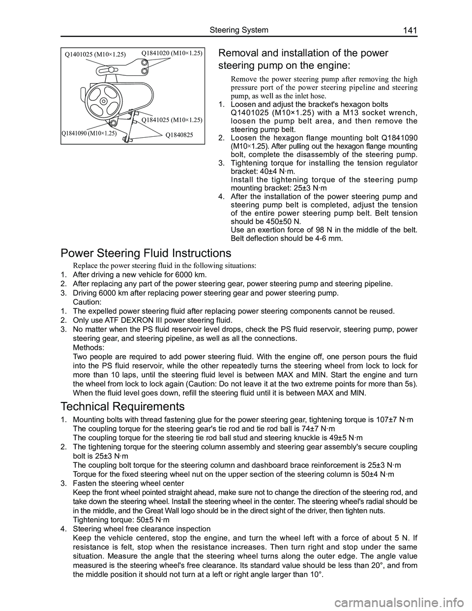
Removal and installation of the power
steering pump on the engine:
Remove the power steering pump after removing the high
pressure port of the power steering pipeline and steering
pump, as well as the inlet hose.
1. Loosen and adjust the bracket's hexagon bolts
Q1401025 (M10×1.25) with a M13 socket wrench,
l o o s e n t h e p u m p b e l t a r e a , a n d t h e n r e m o v e t h e
steering pump belt.
2. Loosen the hexagon flange mounting bolt Q1841090
(M10×1.25). After pulling out the hexagon flange mounting
bolt, complete the disassembly of the steering pump.
3. Tightening torque for installing the tension regulator
bracket: 40±4 N·m.
Install the tightening torque of the steering pump
mounting bracket: 25±3 N·m
4. After the installation of the power steering pump and
steering pump belt is completed, adjust the tension
of the entire power steering pump belt. Belt tension
should be 450±50 N.
Use an exertion force of 98 N in the middle of the belt.
Belt deflection should be 4-6 mm.
Power Steering Fluid Instructions
Replace the power steering fluid in the following situations:
1. After driving a new vehicle for 6000 km.
2. After replacing any part of the power steering gear, power steering pump and steering pipeline.
3. Driving 6000 km after replacing power steering gear and power steering p\
ump.
Caution:
1. The expelled power steering fluid after replacing power steering compone\
nts cannot be reused.
2. Only use ATF DEXRON III power steering fluid.
3. No matter when the PS fluid reservoir level drops, check the PS fluid reservoir, steering pump, power
steering gear, and steering pipeline, as well as all the connections.
Methods:
Two people are required to add power steering fluid. With the engine off, one person pours the fluid
into the PS fluid reservoir, while the other repeatedly turns the steering wheel from lock to lock for
more than 10 laps, until the steering fluid level is between MAX and MIN. Start the engine and turn
the wheel from lock to lock again (Caution: Do not leave it at the two extreme points for more than 5s).
When the fluid level goes down, refill the steering fluid until it is be\
tween MAX and MIN.
Technical Requirements
1. Mounting bolts with thread fastening glue for the power steering gear, tightening torque is 107±7 N·m
The coupling torque for the steering gear's tie rod and tie rod ball is \
74±7 N·m
The coupling torque for the steering tie rod ball stud and steering knuc\
kle is 49±5 N·m
2. The tightening torque for the steering column assembly and steering gear assembly's secure coupling
bolt is 25±3 N·m
The coupling bolt torque for the steering column and dashboard brace rei\
nforcement is 25±3 N·m
Torque for the fixed steering wheel nut on the upper section of the steer\
ing column is 50±4 N·m
3. Fasten the steering wheel center
Keep the front wheel pointed straight ahead, make sure not to change the direction of the steering rod, and
take down the steering wheel. Install the steering wheel in the center. The steering wheel's radial should be
in the middle, and the Great Wall logo should be in the direct sight of the driver, then tighten nuts.
Tightening torque: 50±5 N·m
4. Steering wheel free clearance inspection
Keep the vehicle centered, stop the engine, and turn the wheel left with a force of about 5 N. If
resistance is felt, stop when the resistance increases. Then turn right and stop under the same
situation. Measure the angle that the steering wheel turns along the outer edge. The angle value
measured is the steering wheel's free clearance. Its standard value should be less than 20°, and from
the middle position it should not turn at a left or right angle larger t\
han 10°.
Q1401025 (M10×1.25)Q1841020 (M10×1.25)
Q1841025 (M10×1.25)
Q1840825Q1841090 (M10×1.25)