fuel pressure GREAT WALL FLORID 2008 Service Manual
[x] Cancel search | Manufacturer: GREAT WALL, Model Year: 2008, Model line: FLORID, Model: GREAT WALL FLORID 2008Pages: 281, PDF Size: 43.97 MB
Page 19 of 281
Downloaded from www.Manualslib.com manuals search engine GWFLORID Maintenance Manual12
Ride
Performance
Outter acceleration noise dB (A)≤74≤75
60 km/h constant velocity interior noise dB (A)≤65≤65
Driver operating noise dB (A)≤90≤90
Emission
CO emission (g/km)≤2.30≤1.00≤0.64
HC emission (g/km)≤0.20≤0.10/
NOx emission (g/km)≤0.15≤0.08≤0.5
Particle emission (g/km)//≤0.05
Smoke density//≤4.0
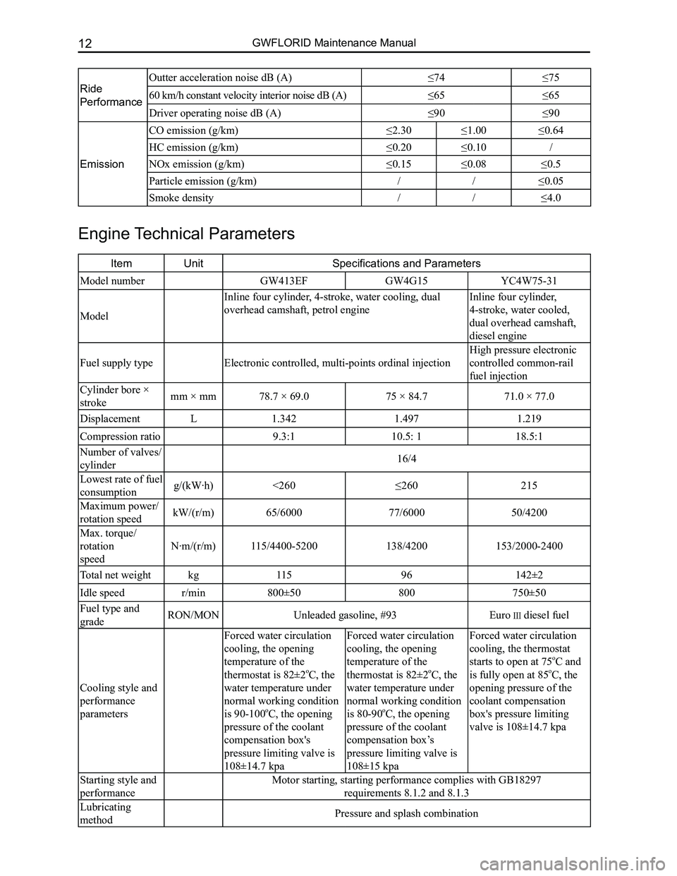
Engine Technical Parameters
ItemUnitSpecifications and Parameters
Model numberGW413EFGW4G15YC4W75-31
Model
Inline four cylinder, 4-stroke, water cooling, dual
overhead camshaft, petrol engine
Inline four cylinder,
4-stroke, water cooled,
dual overhead camshaft,
diesel engine
Fuel supply typeElectronic controlled, multi-points ordinal injection
High pressure electronic
controlled common-rail
fuel injection
Cylinder bore ×
strokemm × mm78.7 × 69.075 × 84.771.0 × 77.0
DisplacementL1.3421.4971.219
Compression ratio9.3:110.5: 118.5:1
Number of valves/
cylinder16/4
Lowest rate of fuel
consumption g/(kW·h)<260≤260215
Maximum power/
rotation speed kW/(r/m)65/600077/600050/4200
Max. torque/
rotation
speed
N·m/(r/m)115/4400-5200138/4200153/2000-2400
Total net weightkg11596142±2
Idle speedr/min800±50800750±50
Fuel type and
gradeRON/MONUnleaded gasoline, #93Euro diesel fuel
Cooling style and
performance
parameters
Forced water circulation
cooling, the opening
temperature of the
thermostat is 82±2oC, the
water temperature under
normal working condition
is 90-100oC, the opening
pressure of the coolant
compensation box's
pressure limiting valve is
108±14.7 kpa
Forced water circulation
cooling, the opening
temperature of the
thermostat is 82±2oC, the
water temperature under
normal working condition
is 80-90oC, the opening
pressure of the coolant
compensation box’s
pressure limiting valve is
108±15 kpa
Forced water circulation
cooling, the thermostat
starts to open at 75oC and
is fully open at 85oC, the
opening pressure of the
coolant compensation
box's pressure limiting
valve is 108±14.7 kpa
Starting style and
performance
Motor starting, starting performance complies with GB18297
requirements 8.1.2 and 8.1.3
Lubricating
methodPressure and splash combination
Page 20 of 281
Downloaded from www.Manualslib.com manuals search engine 13Overall Parameters
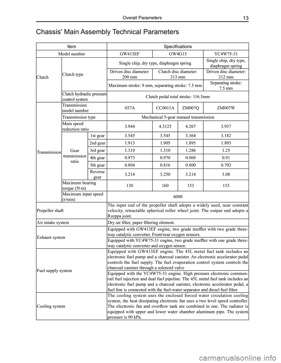
Chassis' Main Assembly Technical Parameters
ItemSpecifications
Model numberGW413EFGW4G15YC4W75-31
ClutchClutch type
Single chip, dry type, diaphragm springSingle chip, dry type,
diaphragm spring
Driven disc diameter:
200 mm
Clutch disc diameter:
213 mm
Driven disc diameter:
212 mm
Maximum stroke: 9 mm, separating stroke: 7.5 mmSeparating stroke:
7.5 mm
Clutch hydraulic pressure
control systemClutch pedal total stroke: 116.5mm
Transmission
Transmission
model number037ACC0011AZM007QZM007W
Transmission typeMechanical 5-gear manual transmission
Main speed
reduction ratio3.9444.31254.2673.937
Gear
transmission
ratio
1st gear3.5453.5453.3643.182
2nd gear1.9131.9051.8951.895
3rd gear1.3101.3101.2861.25
4th gear0.9730.9700.9690.91
5th gear0.8040.8160.8000.703
Reverse
gear3.2143.2503.2143.08
Maximum bearing
torque (N·m)130160153153
Maximum input speed
(r/min)6000
Propeller shaft
The input end of the propeller shaft adopts a widely used, near constant
velocity, retractable spherical roller wheel joint. The output end adopts a
Rzeppa joint.
Air intake systemDry air filter, paper filtering element.
Exhaust system
Equipped with GW413EF engine, two grade muffler with two grade three-
way catalytic converter. Front/rear oxygen sensors.
Equipped with YC4W75-31 engine, two grade muffler with one grade three-
way catalytic converter and oxygen sensor.
Fuel supply system
Equipped with GW413EF engine. The 45L metal fuel tank includes an
electronic fuel pump and a charcoal canister. An electronic accelerator pedal
controls the fuel supply. The fuel evaporation control system controls the
charcoal canister through a solenoid valve
Equipped with the YC4W75-31 engine. High pressure electronic common-
rail fuel injection and dual fuel pipeline. The 45L metal fuel tank includes an
electronic fuel pump and a charcoal canister, electronic accelerator pedal, a
fuel line is connected with the fuel-water separator and diesel fuel filter.
Cooling system
The cooling system uses the enclosed forced water circulation cooling
system, the heat dissipating electronic fan uses a two level speed controller.
The electronic fan and overflow tank are combined in one. The radiator is
equipped with upper and lower water chamber aluminum pipe. The system
pressure is 90 kPa.
Page 24 of 281
Downloaded from www.Manualslib.com manuals search engine 17Overall Parameters
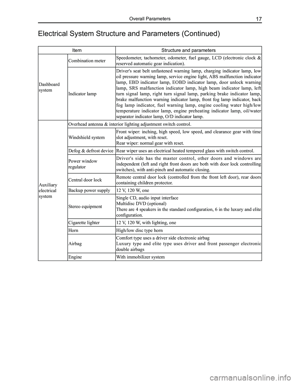
ItemStructure and parameters
Dashboard
system
Combination meter Speedometer, tachometer, odometer, fuel gauge, LCD (electronic clock &
reserved automatic gear indication).
Indicator lamp
Driver's seat belt unfastened warning lamp, charging indicator lamp, low
oil pressure warning lamp, service engine light, ABS malfunction indicator
lamp, EBD indicator lamp, EOBD indicator lamp, door unlock warning
lamp, SRS malfunction indicator lamp, high beam indicator lamp, left
turn signal lamp, right turn signal lamp, parking brake indicator lamp,
brake malfunction warning indicator lamp, front fog lamp indicator, back
fog lamp indicator, fuel warning lamp, engine cooling water high/low
temperature indicator lamp, engine preheating indicator lamp, oil/water
separator indicator lamp, O/D indicator lamp.
Auxiliary
electrical
system
Overhead antenna & interior lighting adjustment switch control.
Windshield system
Front wiper: inching, high speed, low speed, and clearance gear with time
slot adjustment, with reset.
Rear wiper: normal gear with reset.
Defog & defrost deviceRear wiper uses an electrical heated tempered glass with switch control.\
Power window
regulator
D r i v e r ' s s i d e h a s t h e m a s t e r c o n t r o l , o t h e r d o o r s a n d w i n d o w s a r e
independent (left and right front doors are both with door lock controlling
switches), with anti-pinch and automatic closing.
Central door lockRemote central door lock (controlled from the front left door), rear doors
containing children protector.
Backup power supply12 V, 120 W, one
Stereo equipment
Single CD, audio input interface
Multidisc DVD (optional)
There are 4 speakers in the standard configuration, 6 in the luxury and elite
configuration.
Cigarette lighter12 V, 120 W, with lighting, one
HornHigh/low disc type horn
Airbag
Comfort type uses a driver side electronic airbag
Luxury type and elite type uses driver and front passenger electronic
double airbags
EngineWith immobilizer system
Electrical System Structure and Parameters (Continued)
Page 38 of 281
Downloaded from www.Manualslib.com manuals search engine 31Fuel Supply and Exhaust System
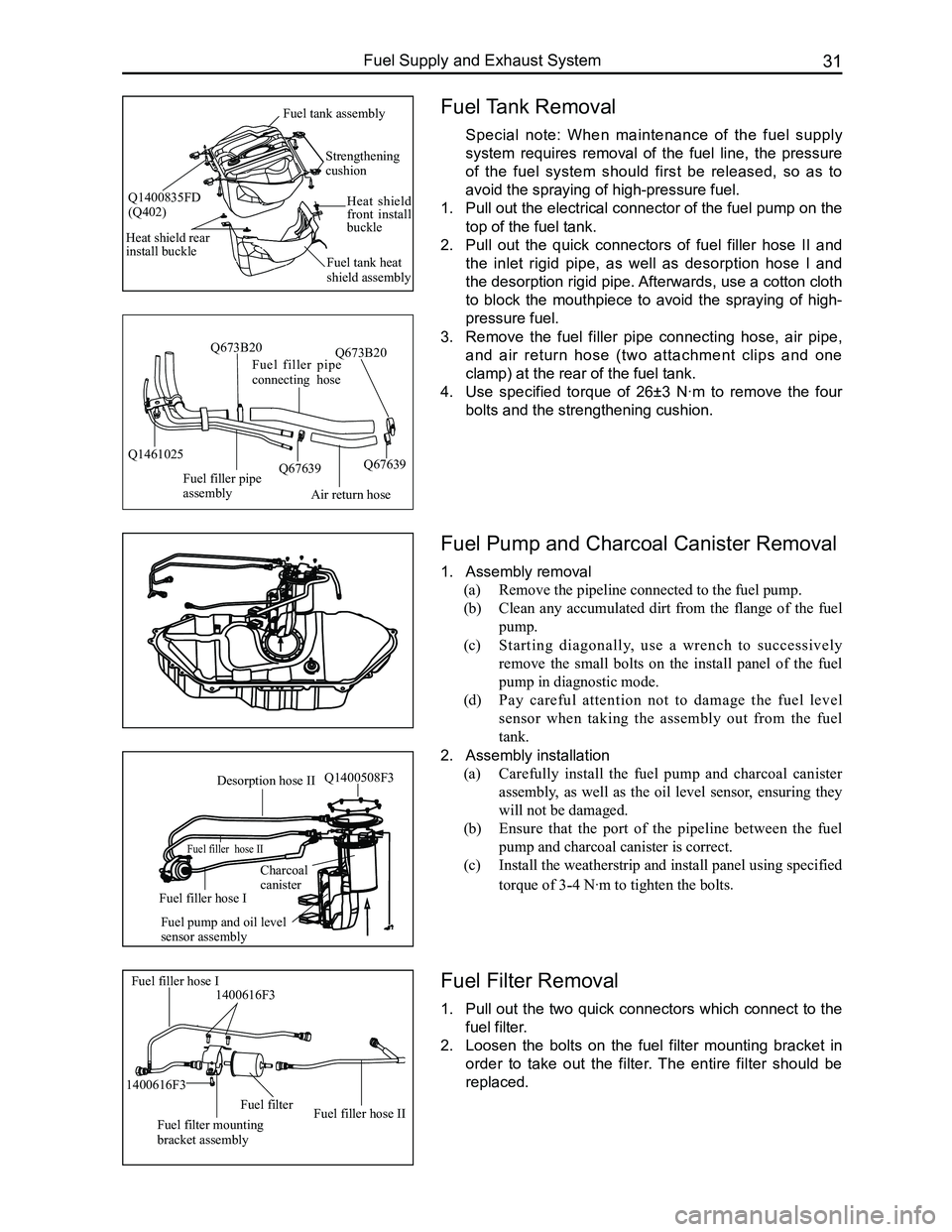
Fuel Tank Removal
Special note: When maintenance of the fuel supply
system requires removal of the fuel line, the pressure
of the fuel system should first be released, so as to
avoid the spraying of high-pressure fuel.
1. Pull out the electrical connector of the fuel pump on the
top of the fuel tank.
2. Pull out the quick connectors of fuel filler hose II and
the inlet rigid pipe, as well as desorption hose I and
the desorption rigid pipe. Afterwards, use a cotton cloth
to block the mouthpiece to avoid the spraying of high-
pressure fuel.
3. Remove the fuel filler pipe connecting hose, air pipe,
and air return hose (two attachment clips and one
clamp) at the rear of the fuel tank.
4. Use specified torque of 26±3 N·m to remove the four
bolts and the strengthening cushion.
Fuel Pump and Charcoal Canister Removal
1. Assembly removal
(a) Remove the pipeline connected to the fuel pump.
(b) Clean any accumulated dirt from the flange of the fuel
pump.
(c) Starting diagonally, use a wrench to successively
remove the small bolts on the install panel of the fuel
pump in diagnostic mode.
(d) Pay careful attention not to damage the fuel level
sensor when taking the assembly out from the fuel
tank.
2. Assembly installation
(a) Carefully install the fuel pump and charcoal canister
assembly, as well as the oil level sensor, ensuring they
will not be damaged.
(b) Ensure that the port of the pipeline between the fuel
pump and charcoal canister is correct.
(c) Install the weatherstrip and install panel using specified
torque of 3-4 N·m to tighten the bolts.
Fuel Filter Removal
1. Pull out the two quick connectors which connect to the
fuel filter.
2. Loosen the bolts on the fuel filter mounting bracket in
order to take out the filter. The entire filter should be
replaced.
Air return hose
Fuel filler pipe connecting hose
Fuel filler pipe assembly
Q1461025Q67639
Q673B20
Q67639
Q673B20
Fuel filler hose I1400616F3
Fuel filter mounting bracket assembly
Fuel filterFuel filler hose II
1400616F3
Desorption hose II
Fuel filler hose II
Fuel filler hose I
Charcoalcanister
Fuel pump and oil level sensor assembly
Q1400508F3
Strengthening cushion
Heat shield front install buckle
Fuel tank heat shield assembly
Heat shield rear install buckle
Fuel tank assembly
Q1400835FD(Q402)
Page 162 of 281
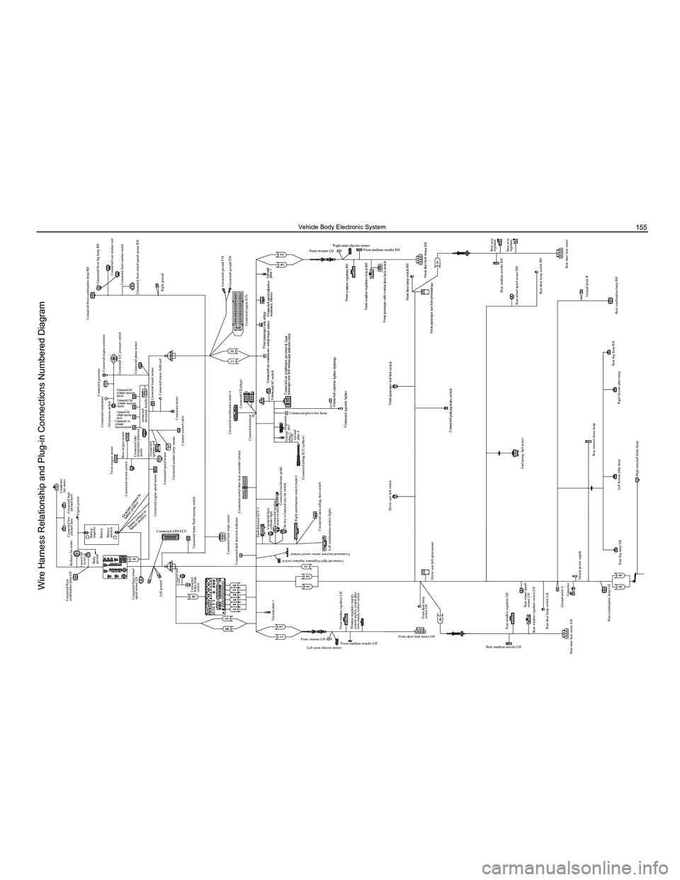
Downloaded from www.Manualslib.com manuals search engine 155Vehicle Body Electronic System
Condenser fan motor
Connected compressor
Oil pressure switch
Front oxygen sensor
Connected reverse switch
Connected engine speed sensor Connected
ignition coil
Connected speed sensor Connected coolant temp. sensor
Canister control valve
Connected combination meter A
Connected antenna
Diagnostic port
Connected AC switch Connected air conditioner temperature sensor
Front passenger side airbag
Connected speed adjustive resistance, blower
Front window regulator RH
Front window regulator switch RH
Front medium woofer RH
Front tweeter LH Right outer electric mirror
Front passenger side central door lock switch
Front door lamp switch RH
Front passenger seat belt pretensioner Front door lock motor RH
Ground
plate 3
Connected cigarette lighter (lighting)
Connected cigarette lighter
Front passenger seat belt switch
Connected parking brake switch Connected air conditioner governor & front
passenger seat belt unfastened indicator lamp
Connected CD player
Connected engine ECUConnected ground P1#
Connected ground P2#
Connected starter
Connected knock sensor
Connected starter field coil
Connected inlet
temperature pressure
sensor
connected
electronic throttle
Rear oxygen sensor
Connected 4th
cylinder injection
nozzle
Connected 3rd
cylinder injection
nozzle
Connected 2nd
cylinder injection
nozzle
Connected 1st
cylinder
injection nozzle
Connected generator
Connected engine armature Connected front combination lamp RH
Connected front fog lamp RH
Connected rear washer motor
Connected front washer motor
Connected front wheel speed sensor RH
Right ground
Connected A/C pressure switch
Connected phase sensor
Connected low
pitched horn
Connected front
combination lamp LH
Rediator fan motor
Connected front
fog lamp LH
Connected high pitched horn
Battery
negative
Body
ground
Battery
Left ground Connected
brake lamp
switch Connected brake fluid warning switch
Connected theft deterrent indicator Theft deterrent ECU 1Connected lock
cylinder lightConnected ignition
switch (white)
The key is inserted into the switch
Right combination switch (wiper) Connected airbag ECU (yellow)Ground
plate 2
Ground
plate 4
Connected accelerator pedal
Ground plate 1
Left outer electric mirror
Front medium woofer LH Front door lock motor LH
Rear medium woofer LH
Rear window regulator switch LH
Rear door lock motor LH Rear door lamp switch LH
Ground point ACapacitor
Vehicle power supply
Rear fog lamp LH Left license plate lamp
High mounted brake lamp
Ground point Trunk opener switch
Trunk motorRear wiper motor
Rear windshield defroster “-”
Trunk lamp switch Right license plate lamp
Rear fog lamp RH
Rear combination lamp RHRear wheel speed sensor RH
Rear window
regulator RH
Rear window
regulator switch RH
Rear door lock motor RH
Rear door lamp switch RH Rear medium woofer RH
Ground point B
Rear combination lamp LH
Rear windshield defroster “+”
Rear wheel speed
sensor LH
Rear window regulator LH
Fuel pump, fuel sensor
Rear interior dome lamp
Front door lamp
switch LH
Driver seat belt pretensioner Driver seat belt switch
Front tweeter LH
Connected light brightness regulator switch
Connected rearview mirror switch (white)
Connected glove box lamp
Front window regulator LH Left combination switch (light)
Connected main airbag, horn switch
Window regulator mainly
control switch, central door
lock mainly control switch Connected central door lock controller (white)
Connected front wiper motor
Connected clutch
switch
Connected ABS ECUBattery
positive
Connected front wheel
speed sensor LH Engine groud
Starter connect to
battery positive
Generator connect to
battery positive
Wire Harness Relationship and Plug-in Connections Numbered Diagram
Page 176 of 281
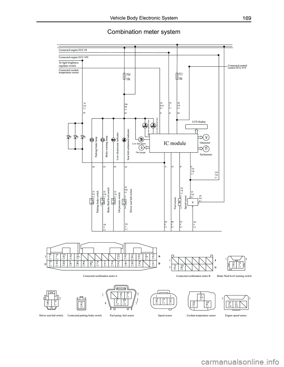
Downloaded from www.Manualslib.com manuals search engine 169Vehicle Body Electronic System
Combination meter system
Connected engine ECU #8
Connected engine ECU #59
To light brightness
regulator switch
Parking brake lamp
Parking brake switch
Brake fluid level switch
Oil pressure switch
Driver seat belt switch
Fuel sensor
Speed sensor
Connected combination meter A
Driver seat belt switch Connected parking brake switch Fuel pump, fuel sensor Coolant temperature sensor Engine speed sensor
Speed sensor Connected combination meter B
Brake fluid level warning switch
Brake warning lamp
Low oil pressure indicator
Seat belt unfastened indicator
Low fuel alarm Fuel gauge
High water temperature alarm
Low water temperature alarm
Connected coolant
temperature sensor Connected central
control ECU #18
IC module
LCD display
Odometer
Tachometer
Page 180 of 281
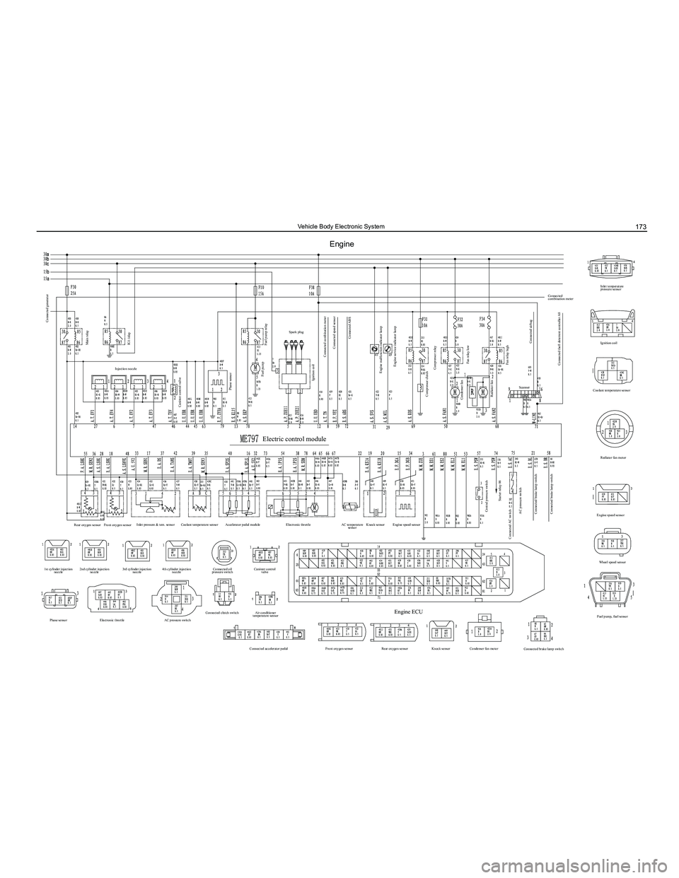
Downloaded from www.Manualslib.com manuals search engine 173Vehicle Body Electronic System
Engine
Connected generator
Canister control valve
Rear oxygen sensor
1st cylinder injection nozzle
Phase sensor Electronic throttle AC pressure switchConnected clutch switch
Air conditioner
temperature sensor
Connected accelerator pedal Front oxygen sensorRear oxygen sensorKnock sensorCondenser fan motor
Connected brake lamp switch
Engine ECU
2nd cylinder injection
nozzle 3rd cylinder injection
nozzle 4th cylinder injection
nozzle Connected oil
pressure switch Canister control
valve
Front oxygen sensor
Inlet pressure & tem. sensor
Coolant temperature sensor Accelerator pedal module Electronic throttle AC temperature
sensor Knock sensor
Engine speed sensor
Phase sensor
Fuel pump relay
Connected combination meter Connected speed sensor
Engine malfunction indicator lamp Engine service indicator lamp
Compressor relay
Compressor clutch
Central pressure switch Starter relay 86
Connected AC switch AC pressure switch
Connected brake lamp switch
Connected brake lamp switch Condenser fan
Rediator fan Fan relay lowScanner
Fan relay high
Connected airbag
Connected theft deterrent controller A8
Connected
combination meter
Ignition coil
Coolant temperature sensor
Rediator fan motor
Engine speed sensor Wheel speed sensor
Fuel pump, fuel sensor Inlet temperature
pressure sensor
Connected ABS
Spark plug
Fuel pump
Electric control module
Ignition coil
Main relay
Injection nozzle
IG1 relay
Page 187 of 281
Downloaded from www.Manualslib.com manuals search engine GWFLORID Maintenance Manual180
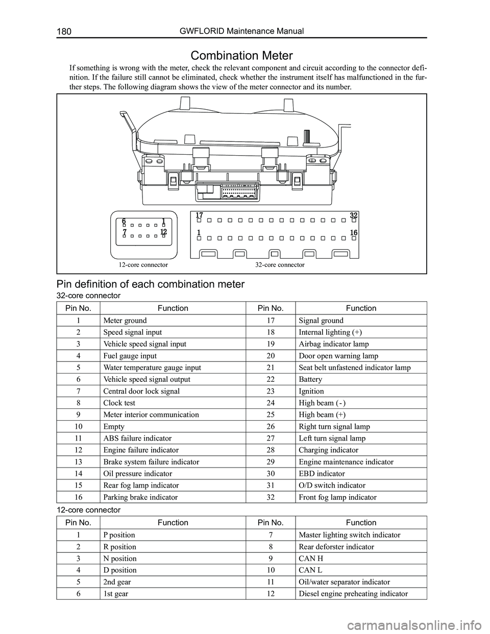
Combination Meter
If something is wrong with the meter, check the relevant component and circuit according to the connector defi-
nition. If the failure still cannot be eliminated, check whether the instrument itself has malfunctioned in the fur-
ther steps. The following diagram shows the view of the meter connector and its numb\
er.
Pin definition of each combination meter
32-core connector
Pin No.FunctionPin No.Function
1Meter ground17Signal ground
2Speed signal input18Internal lighting (+)
3Vehicle speed signal input19Airbag indicator lamp
4Fuel gauge input20Door open warning lamp
5Water temperature gauge input21Seat belt unfastened indicator lamp
6Vehicle speed signal output22Battery
7Central door lock signal23Ignition
8Clock test24High beam ( - )
9Meter interior communication25High beam (+)
10Empty26Right turn signal lamp
11ABS failure indicator27Left turn signal lamp
12Engine failure indicator28Charging indicator
13Brake system failure indicator29Engine maintenance indicator
14Oil pressure indicator30EBD indicator
15Rear fog lamp indicator31O/D switch indicator
16Parking brake indicator32Front fog lamp indicator
12-core connector
Pin No.FunctionPin No.Function
1P position7Master lighting switch indicator
2R position8Rear deforster indicator
3N position9CAN H
4D position10CAN L
52nd gear11Oil/water separator indicator
61st gear12Diesel engine preheating indicator
12-core connector32-core connector