ignition GREAT WALL FLORID 2008 Service Manual
[x] Cancel search | Manufacturer: GREAT WALL, Model Year: 2008, Model line: FLORID, Model: GREAT WALL FLORID 2008Pages: 281, PDF Size: 43.97 MB
Page 12 of 281
Downloaded from www.Manualslib.com manuals search engine 5Overview
The white side
The black side
7. Pay attention to the "Areas of Importance" below to
avoid damaging any part:
(a) Do not open the cover or case of the ECU (Electronic
Control Unit) unless it's absolutely necessary. (Touching
the pin of the IC (Integrated Circuit) may damage the
IC due to static electricity.)
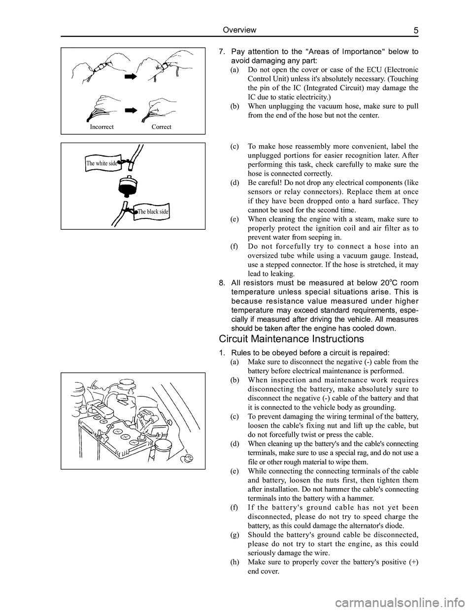
(b) When unplugging the vacuum hose, make sure to pull
from the end of the hose but not the center.
IncorrectCorrect
(c) To make hose reassembly more convenient, label the
unplugged portions for easier recognition later. After
performing this task, check carefully to make sure the
hose is connected correctly.
(d) Be careful! Do not drop any electrical components (like
sensors or relay connectors). Replace them at once
if they have been dropped onto a hard surface. They
cannot be used for the second time.
(e) When cleaning the engine with a steam, make sure to
properly protect the ignition coil and air filter as to
prevent water from seeping in.
(f) D o n o t f o r c e f u l l y t r y t o c o n n e c t a h o s e i n t o a n
oversized tube while using a vacuum gauge. Instead,
use a stepped connector. If the hose is stretched, it may
lead to leaking.
8. All resistors must be measured at below 20oC room
temperature unless special situations arise. This is
because resistance value measured under higher
temperature may exceed standard requirements, espe-
cially if measured after driving the vehicle. All measures
should be taken after the engine has cooled down.
Circuit Maintenance Instructions
1. Rules to be obeyed before a circuit is repaired:
(a) Make sure to disconnect the negative (-) cable from the
battery before electrical maintenance is performed.
(b) W h e n i n s p e c t i o n a n d m a i n t e n a n c e w o r k r e q u i r e s
disconnecting the battery, make absolutely sure to
disconnect the negative (-) cable of the battery and that
it is connected to the vehicle body as grounding.
(c) To prevent damaging the wiring terminal of the battery,
loosen the cable's fixing nut and lift up the cable, but
do not forcefully twist or press the cable.
(d) When cleaning up the battery's and the cable's connecting
terminals, make sure to use a special rag, and do not use a
file or other rough material to wipe them.
(e) While connecting the connecting terminals of the cable
and battery, loosen the nuts first, then tighten them
after installation. Do not hammer the cable's connecting
terminals into the battery with a hammer.
(f) I f t h e b a t t e r y ' s g r o u n d c a b l e h a s n o t y e t b e e n
disconnected, please do not try to speed charge the
battery, as this could damage the alternator's diode.
(g) Should the battery's ground cable be disconnected,
please do not try to start the engine, as this could
seriously damage the wire.
(h) Make sure to properly cover the battery's positive (+)
end cover.
Page 103 of 281
Downloaded from www.Manualslib.com manuals search engine GWFLORID Maintenance Manual96
Brake System Maintenance
Brake fluid inspection and replacement
Brake fluid directly influences the brake performance and the operating conditions and use life of the brake
system components. Brake fluid has very strong hygroscopic properties, and thus absorbs water easily,
which will then deteriorate the metal and rubber pieces. Polluted and deteriorated brake fluid or its mixture
would cause the brake fluid to boil and gasify, hence reduces braking efficiency. Therefore, pay attention to
the items below when filling or changing the brake fluid:
1. Containers used to hold brake fluid must be tightly closed and sealed
2. Brake fluid is poisonous and damaging to the paint. Hence if it gets on the vehicle surface, rub it
off at once
3. If water or other contaminates found in the brake fluid, and the brake master cylinder's piston seal
has been broken, then the brake fluid and all the rubber pieces inside the brake system including
the brake hose must be replaced
4. The correct brake fluid level in the reservoir must be between MAX and MIN. After the vehicle has
been driven for over 1000 km, check the brake fluid level in the reservoir. If the brake fluid level is
not up to regulation, more brake fluid should be added to the reservoir \
until it reaches MAX.
Hydraulic component inspection and system flushing
1. If the oil-based solvent gets into the hydraulic system, flush the whole system and change all of
the rubber pieces
2. Clean your hands before installing new rubber pieces or other components
3. Do not use regular solvents (kerosene, gas, etc.) when inspecting or cleaning hydraulic
components, instead use absorbing alcohol or brake fluid
4. After inspecting the components, drain the brake fluid from the system. Use new brake fluid to
flush the system. Afterwards, add new brake fluid to perform hydraulic system exhaust
5. Flushing completion sign: When the brake fluid flowing out of the dump valve is clear from any
contaminate.
Hydraulic pressure system drainage
If the brake fluid inside the whole hydraulic pressure system needs to be emptied, open all the bleed screws
with each connected to a hose, as to allow the brake fluid to flow into a container. Step on the pedal slowly
until only air flows out. During the whole procedure, make sure all the \
valves are open.
Hydraulic pressure system air bleeding
The hydraulic brake system must work under a vacuum environment. The air will cause spongy brake or
overall brake failure when it flows into the hydraulic system. It is extremely necessary to bleed system air
when performing any operation on the brake system or if any air inside t\
he brake system is suspected.
1. Air bleeding sequence
If air inside the brake master cylinder is suspected, first perform air bleeding.
(a) If numerous valves are equipped, air bleed each valve
(b) Another sequence principle is: Air bleed from the wheel brake furthest away from the master cylinder.
The air bleeding sequence for the LHD modules is: rear right wheel - left rear wheel - front right wheel
- front left wheel, Right rudder vehicles: rear right wheel - left rear wheel - front left wheel - front right
wheel.
2. Air bleeding method
(1) Manual air bleeding
Use the brake pedal or pump as the air bleeding power source. When the air bleed screws are open, vent the
brake fluid containing the bubbles from the system. Usually this is simultaneously done by two people. One
steps on the brake pedal and the other operates the air bleed screws. Important points to take note of when
performing the operation:
(a) Place the ignition switch to the off position and step on the pedal repeatedly to remove the
vacuum pressure or hydraulic pressure.
(b) Before and after air bleeding, add clean brake fluid into the master cylinder until it reaches
the correct (stated) level.
(c) Check the fluid level frequently to make sure that more than half of the reservoir's capacity is
available.
(d) Bleed screws should only be opened when the pedal is pressed down, and closed before the
pedal is loosened. Meanwhile, check if the vented brake fluid has bubble\
s inside.
Page 104 of 281
Downloaded from www.Manualslib.com manuals search engine 97Brake System
(e) Make sure not to let the system valves block the air bleeding.
(f) When the brake fluid that flows out of the hose or connector has no bubbles, it means that the air
in the system has been exhausted. There is still air inside the system if the hose inserted into the
brake fluid is still bubbling when pressing down the pedal.
(g) Keep the free end of the hose immerged in the brake fluid to avoid air from flowing into the
system while opening the screw.
(h) While air bleeding, hammer the casting part of the vibrating brake device with a rubber hammer.
This is helpful for removing bubbles deep in the brake fluid.
(i) If air in the master cylinder is suspected, then perform air bleeding on the master cylinder first,
then the wheel cylinder or brake caliper.
(j) When releasing air from the tires, generally make sure to release air out of all the tires.
(k) To avoid the possibility of air reversely entering into the system, a bleeder hose that has a check
valve could be used.
(2) Pressure blow-off
Under the proper conditions, a pressure blow-off device can be used to release the air inside the brake system.
3. Air releasing sequence
(1) Master cylinder air bleeding
If the master cylinder does not have air bleed screws, perform the follo\
wing steps:
(a) Check the brake fluid level inside the master cylinder’s reservoir and add to it if necessary.
(b) Slowly take off the front brake pipe connector until the brake fluid flows out from the end.
(c) Reconnect the brake pipe, but do not tighten it.
(d) Slowly step down and press on the brake pedal, check if the brake fluid flowing out of the connector
contains bubbles.
(e) Tighten the pipe fitting.
(f) Have the assistant loosen the pedal, wait for 15 s.
(g) Repeat the above steps until all the air is released.
(h) Take off the rear brake pipe connector, repeat the above steps.
(2) Wheel brake air releasing
(a) Check the brake fluid level inside the master cylinder’s reservoir and add to it if necessary. During the
entire air releasing period, check repeatedly and add promptly.
(b) Connect one end of the bleeder hose with the bleed screw and the other end immerged in the brake fluid.
(c) Have the assistant step on the pedal several times, raise the pedal gradually until it cannot be stepped on
any more, then forcibly press on the pedal once more.
(d) Loosen the bleed screw, check if there are any bubbles in the brake fluid flowing out. Meanwhile, slowly
lower the pedal.
(e) When the brake pedal is close to the stroke end or the out flowing brake fluid does not have any bubbles,
tighten the bleed screw.
(f) Have the assistant release the pedal and wait for 15 s.
(g) Repeat the above steps until there are no bubbles in the flowing brake fluid when the screw is loosened.
(h) Release the air for all the wheels in turn using the same method.
(i) After releasing the air from the entire system, switch the ignition to the on position.
(j) Inspect the stroke of the brake pedal and its reaction.
(k) Inspect the lighting condition of the brake warning lamp, and repeatedly perform maintenance or air
bleeding if necessary.
( l ) Add brake fluid to the reservoir until the specified fluid level, air bleeding is complete.
Page 116 of 281
Downloaded from www.Manualslib.com manuals search engine 109Brake System
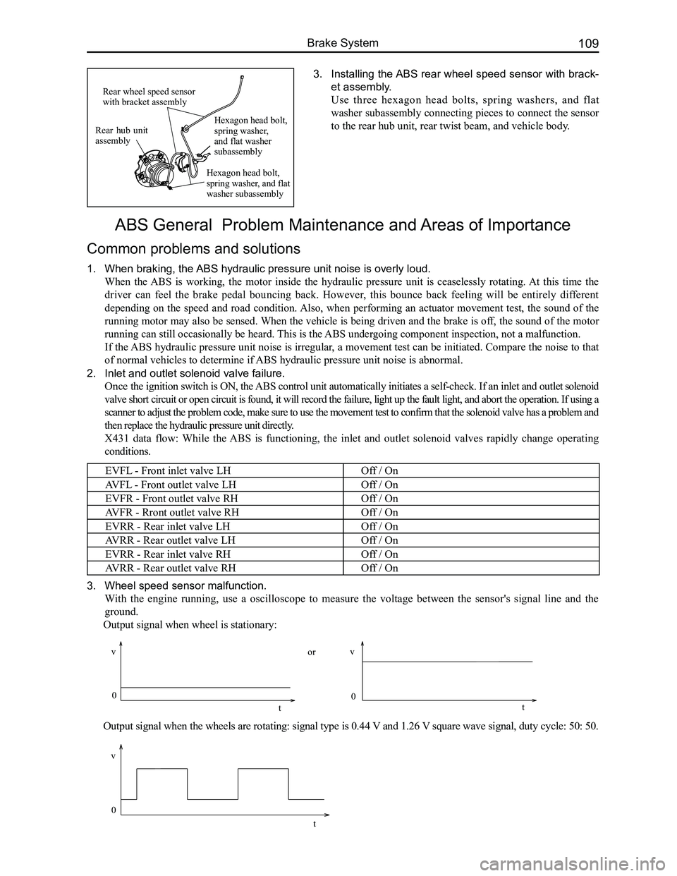
3. Installing the ABS rear wheel speed sensor with brack-
et assembly.
Use three hexagon head bolts, spring washers, and flat
washer subassembly connecting pieces to connect the sensor
to the rear hub unit, rear twist beam, and vehicle body.
ABS General Problem Maintenance and Areas of Importance
Common problems and solutions
1. When braking, the ABS hydraulic pressure unit noise is overly loud.
When the ABS is working, the motor inside the hydraulic pressure unit is ceaselessly rotating. At this time the
driver can feel the brake pedal bouncing back. However, this bounce back feeling will be entirely different
depending on the speed and road condition. Also, when performing an actuator movement test, the sound of the
running motor may also be sensed. When the vehicle is being driven and the brake is off, the sound of the motor
running can still occasionally be heard. This is the ABS undergoing component inspection, not a malfunction.
If the ABS hydraulic pressure unit noise is irregular, a movement test can be initiated. Compare the noise to that
of normal vehicles to determine if ABS hydraulic pressure unit noise is abnormal.
2. Inlet and outlet solenoid valve failure.
Once the ignition switch is ON, the ABS control unit automatically initiates a self-check. If an inlet and outlet solenoid
valve short circuit or open circuit is found, it will record the failure, light up the fault light, and abort the operation. If using a
scanner to adjust the problem code, make sure to use the movement test t\
o confirm that the solenoid valve has a problem and
then replace the hydraulic pressure unit directly.
X431 data flow: While the ABS is functioning, the inlet and outlet solenoid valves rapidly change operating
conditions.
EVFL - Front inlet valve LHOff / On
AVFL - Front outlet valve LHOff / On
EVFR - Front outlet valve RHOff / On
AVFR - Rront outlet valve RHOff / On
EVRR - Rear inlet valve LHOff / On
AVRR - Rear outlet valve LHOff / On
EVRR - Rear inlet valve RHOff / On
AVRR - Rear outlet valve RHOff / On
3. Wheel speed sensor malfunction.
With the engine running, use a oscilloscope to measure the voltage between the sensor's signal line and the
ground.
Output signal when wheel is stationary:
Output signal when the wheels are rotating: signal type is 0.44 V and 1.26 V square wave signal, duty cycle: 50: 50.
Rear hub unit assembly
Rear wheel speed sensor with bracket assembly
Hexagon head bolt, spring washer, and flat washer subassembly
Hexagon head bolt, spring washer, and flat washer subassembly
0
v
t
vv
0 0
tt
or
Page 117 of 281
Downloaded from www.Manualslib.com manuals search engine GWFLORID Maintenance Manual110
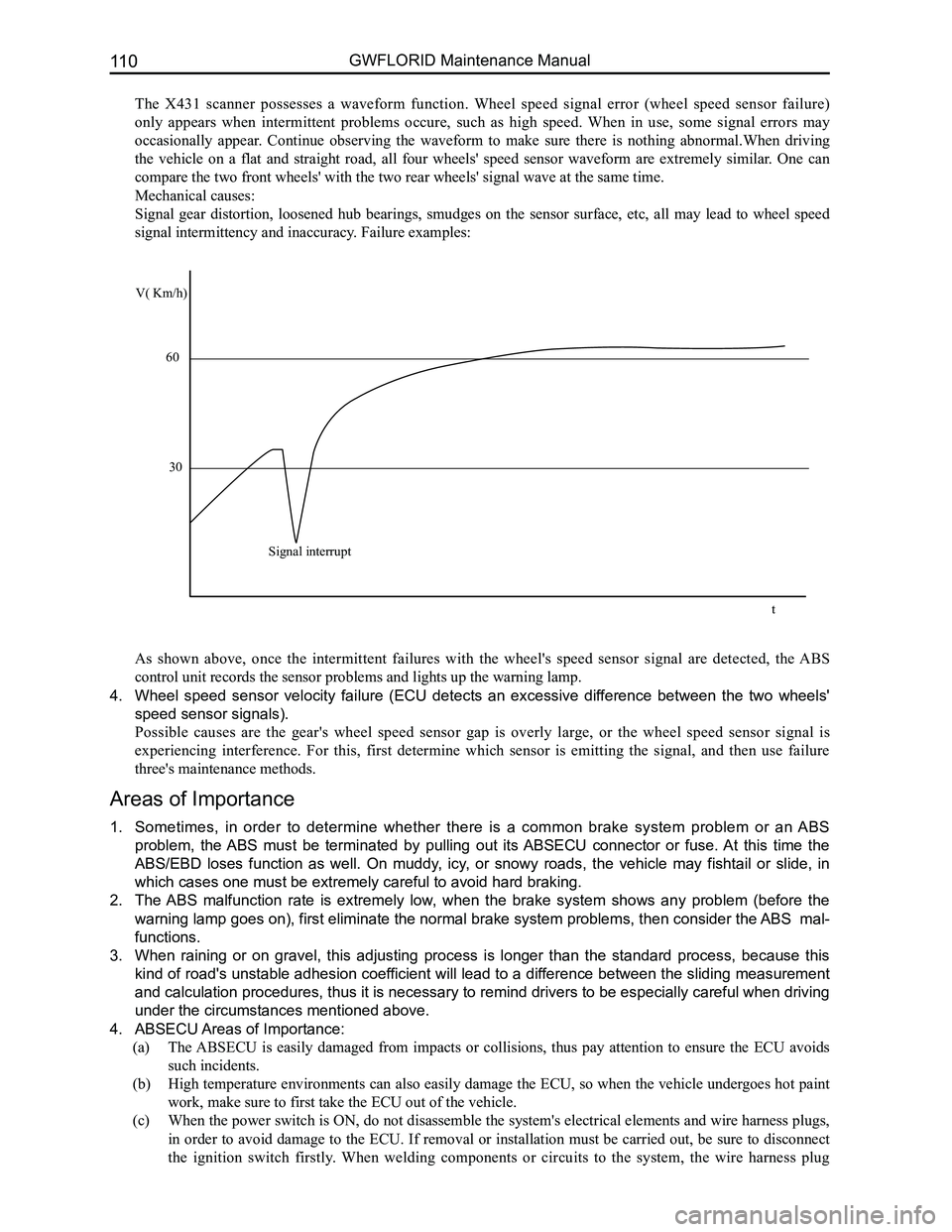
The X431 scanner possesses a waveform function. Wheel speed signal error (wheel speed sensor failure)
only appears when intermittent problems occure, such as high speed. When in use, some signal errors may
occasionally appear. Continue observing the waveform to make sure there is nothing abnormal.When driving
the vehicle on a flat and straight road, all four wheels' speed sensor waveform are extremely similar. One can
compare the two front wheels' with the two rear wheels' signal wave at t\
he same time.
Mechanical causes:
Signal gear distortion, loosened hub bearings, smudges on the sensor surface, etc, all may lead to wheel speed
signal intermittency and inaccuracy. Failure examples:
As shown above, once the intermittent failures with the wheel's speed sensor signal are detected, the ABS
control unit records the sensor problems and lights up the warning lamp.\
4. Wheel speed sensor velocity failure (ECU detects an excessive difference between the two wheels'
speed sensor signals).
Possible causes are the gear's wheel speed sensor gap is overly large, or the wheel speed sensor signal is
experiencing interference. For this, first determine which sensor is emitting the signal, and then use failure
three's maintenance methods.
Areas of Importance
1. Sometimes, in order to determine whether there is a common brake system problem or an ABS
problem, the ABS must be terminated by pulling out its ABSECU connector or fuse. At this time the
ABS/EBD loses function as well. On muddy, icy, or snowy roads, the vehicle may fishtail or slide, in
which cases one must be extremely careful to avoid hard braking.
2. The ABS malfunction rate is extremely low, when the brake system shows any problem (before the
warning lamp goes on), first eliminate the normal brake system problems, then consider the ABS mal-
functions.
3. When raining or on gravel, this adjusting process is longer than the standard process, because this
kind of road's unstable adhesion coefficient will lead to a difference between the sliding measurement
and calculation procedures, thus it is necessary to remind drivers to be especially careful when driving
under the circumstances mentioned above.
4. ABSECU Areas of Importance:
(a) The ABSECU is easily damaged from impacts or collisions, thus pay attention to ensure the ECU avoids
such incidents.
(b) High temperature environments can also easily damage the ECU, so when the vehicle undergoes hot paint
work, make sure to first take the ECU out of the vehicle.
(c) When the power switch is ON, do not disassemble the system's electrical elements and wire harness plugs,
in order to avoid damage to the ECU. If removal or installation must be carried out, be sure to disconnect
the ignition switch firstly. When welding components or circuits to the system, the wire harness plug
V( Km/h)
60
30
Signal interrupt
t
Page 145 of 281
Downloaded from www.Manualslib.com manuals search engine GWFLORID Maintenance Manual138
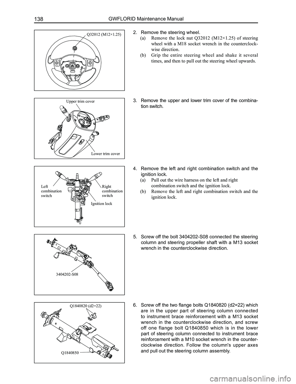
2. Remove the steering wheel.
(a) Remove the lock nut Q32012 (M12×1.25) of steering
wheel with a M18 socket wrench in the counterclock-
wise direction.
(b) Grip the entire steering wheel and shake it several
times, and then to pull out the steering wheel upwards.
3. Remove the upper and lower trim cover of the combina-
tion switch.
4. Remove the left and right combination switch and the
ignition lock.
(a) Pull out the wire harness on the left and right
combination switch and the ignition lock.
(b) Remove the left and right combination switch and the
ignition lock.
5. Screw off the bolt 3404202-S08 connected the steering
column and steering propeller shaft with a M13 socket
wrench in the counterclockwise direction.
6. Screw off the two flange bolts Q1840820 (d2=22) which
are in the upper part of steering column connected
to instrument brace reinforcement with a M13 socket
wrench in the counterclockwise direction, and screw
off one flange bolt Q1840850 which is in the lower
part of steering column connected to instrument brace
reinforcement with a M10 socket wrench in the counter-
clockwise direction. Follow the column's upper axes
and pull out the steering column assembly.
Q32012 (M12×1.25)
Lower trim cover
Upper trim cover
3404202-S08
Q1840820 (d2=22)
Q1840850
Right combination switch
Left combination switch
Ignition lock
Page 150 of 281
Downloaded from www.Manualslib.com manuals search engine 143Vehicle Body Electronic System
Basic Information on the Electrical System
Electrical system schematics reading instructions
1. Configuration introduction
The GWFLORID comes in three configurations: comfort, luxury and elite. The wire harness has two types of
configurations: One is a non jam protection comfort model, which is a combination of both comfort and luxury
type, the other type is called elite. These two configurations are universally used in most of this manual. The
parts that are only available for the non jam protection comfort type have been marked in this manual, please
pay attention to these sections while performing maintenance.
2. Fuse box and power supply introduction
The fuse box located inside the left side of the dashboard is No. 1 Fuse Box, the other one inside the left side of
the engine compartment is No. 2 Fuse Box.
• 30 represents a power cord for normal power, which is from the battery positive fuse box-60 A.
• 30a represents a power cord for normal power, which is from the battery positive fuse box-120 A.
• 30b represents a power cord for normal power, which is from the battery positive fuse box-120 A.
• 15 represents a power cord for small capacity electronics. When the ignition switch is at the "ON" position,
power is supplied by relay IG.
• 15a represents a power cord for small capacity electronics. When the ignition switch is at the "ON"
position, power is directly supplied by ignition switch IG1.
• 15b represents a power cord for small capacity electronics. When the ignition switch is at the "ON"
position, power is directly supplied by ignition switch IG2.
• X represents a power cord for small capacity electronics. When the ignition switch is at the "ACC"
position, power is supplied by relay ACC.
4. Wire's color and sectional area (mm2)
B-BlackW-WhiteR-RedBl-BlueBr-BrownY-Yellow
G-GreenP-PinkOr-OrangeV-VioletLg-Light greenGr-Gray
Mark the solid-colored wires with the letters in the above table. Double-colored wires' first letter is the primary
color, second letter is the secondary color.
For example:
Solid-colored wire: Red, marked as R.
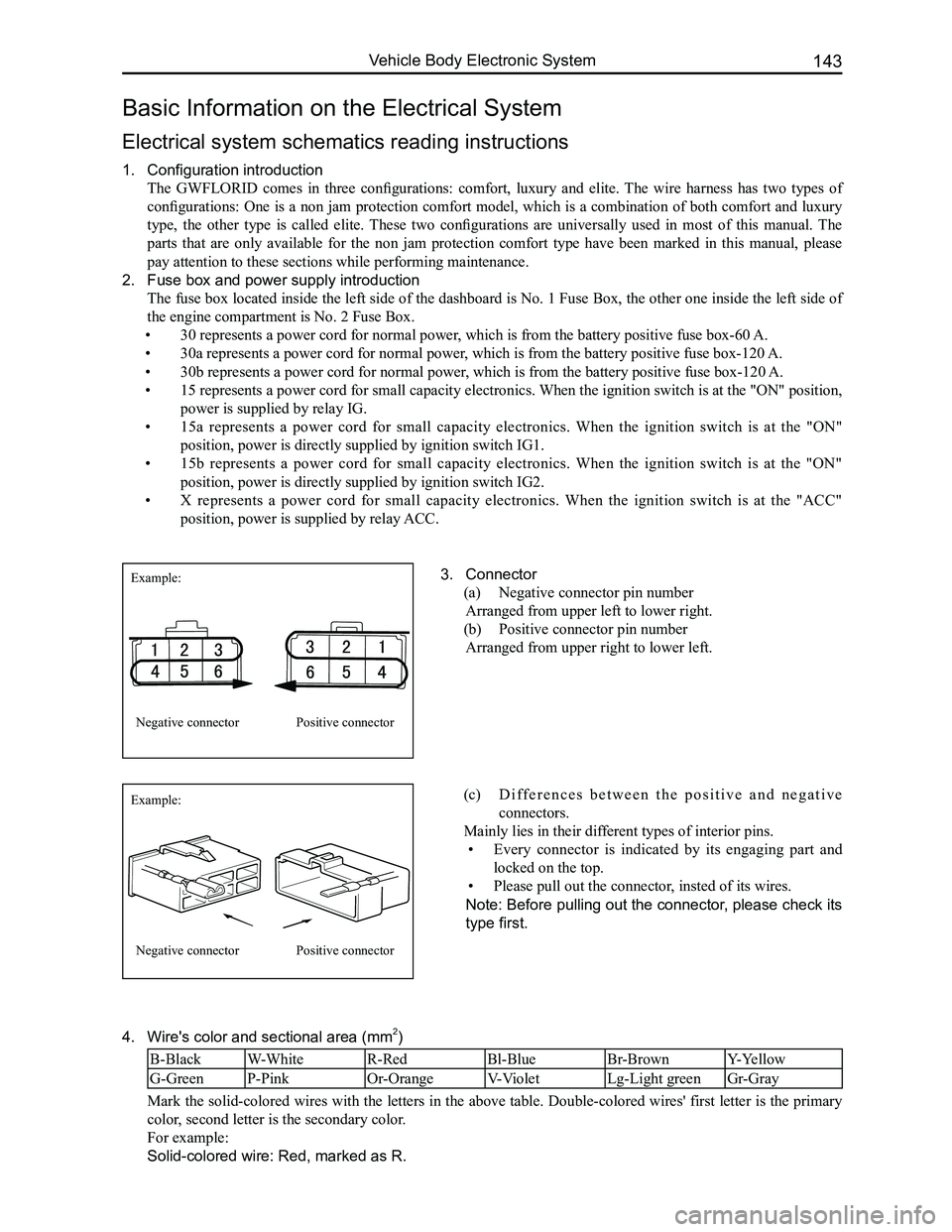
3. Connector
(a) Negative connector pin number
Arranged from upper left to lower right.
(b) Positive connector pin number
Arranged from upper right to lower left.
Example:
Example:
Negative connector
Negative connector
Positive connector
Positive connector
(c) D i f f e r e n c e s b e t w e e n t h e p o s i t i v e a n d n e g a t i v e
connectors.
Mainly lies in their different types of interior pins.
• Every connector is indicated by its engaging part and
locked on the top.
• Please pull out the connector, insted of its wires.
Note: Before pulling out the connector, please check its
type first.
Page 151 of 281
Downloaded from www.Manualslib.com manuals search engine GWFLORID Maintenance Manual144
Double-colored wire: Primary color is Red, secondary color is Blue, mark\
ed as RBl.
0.5BrGr means Brown wire with a Gray fine wire, and sectional area is 0.\
5 mm2.
Areas of importance in circuit maintenance
1. Before operating any electronic devices, and when tools or maintenance devices may easily make
contact with an uncovered electronic terminal, please make sure to turn the ignition switch to the LOCK
position, and then disconnect the battery's negative cable to avoid injury or vehicle damage. When the
ignition switch is on the ON position, please do not disconnect the battery's connecting wire or take out
the power's fuse, regardless if the engine is running or not.Otherwise it would seriously damage the
ECU and related microelectronic devices such as sensors.
2. When changing the fuse, please make sure that the new fuse possesses the proper current rating,
and is not above or below this rating.
3. When repairing the wire harnesses of the airbag and pretensioner, only specified contact points,
plugs, and wires are allowed to be used.
4. Before repairing the wire harness, make sure to eliminate any factor that might cause damage,
for example, the edge of a vehicle body part is too sharp, or the used electronics are damaged or
corroded.
5. Shielded wire should not be repaired, it must be replaced entirely once it is damaged.
6. Unless it is specified during the test, please do not use an analog multimeter to test the ECU and
sensor, instead use a high-impedance digital multimeter (internal resistance should be ≥10 kΩ) or a
vehicle multimeter for inspection.
7. When inspecting the connector with a digital multimeter, take the waterproof rubber cover off the
connector, and tightly insert the test pen along the connecting terminal. Don't use too much force, as
to avoid cracking the connector.
Circuit inspection steps
The principle of troubleshooting is to confirm the "possible cause". Once the possible cause is confirmed, the
components that need to be inspected are limited to the components that are related to the possible cause. The
confirmed possible cause should be based on theory and be supported by facts, but not just by intuition. If
one tries to solve the problem but does not adopt the proper troubleshooting steps, it may make the problem
worse. Then the possible cause not only can't be confirmed, but also maintenance can't be performed properly.
Troubleshooting should adhere to the four steps below:
1. Observe the symptoms carefully, inspect if there is anything else abnormal, and record it.
2. While confirming the possible causes, study the circuit diagram carefully, and regard it as a whole
system in order to understand the circuit. Thorough knowledge of switches, relays, and other
electronic components is obligatory for proper analysis.
3. Inspect and eliminate the problems one by one until the cause is found.
4. After the malfunction is fixed, make sure to check if the inspected system is working properly, and also
check if the maintenance may have caused any new problems.
Compres-
sor relay
Reserve
Sunroof (Elite) Lamplet
Reserve
Reserve
Reserve
Reserve Door and window Reserve Blower
Lamplet
relay Flasher relay Blower high
speed relay (Elite) Door and
window relay (Comfort, Luxury) Blower relay
Reserve
Front fog lamp
Combination
meter
Interior
lighting
central
door lock
brake lamp
CD player
Reserve
Reserve
Reserve
Cigarette
lighter
Rearview
mirror
Front wiper
Charge
Airbag
Reserve
Reverse lamp Rear fog lamp
Rear wiper
Defroster Compressor
ACC relay
IG relayRear wiper
relay Defroster
relay
Front fog
lamp relay Rear fog
lamp relay
Warning lamp
Turn signal lamp
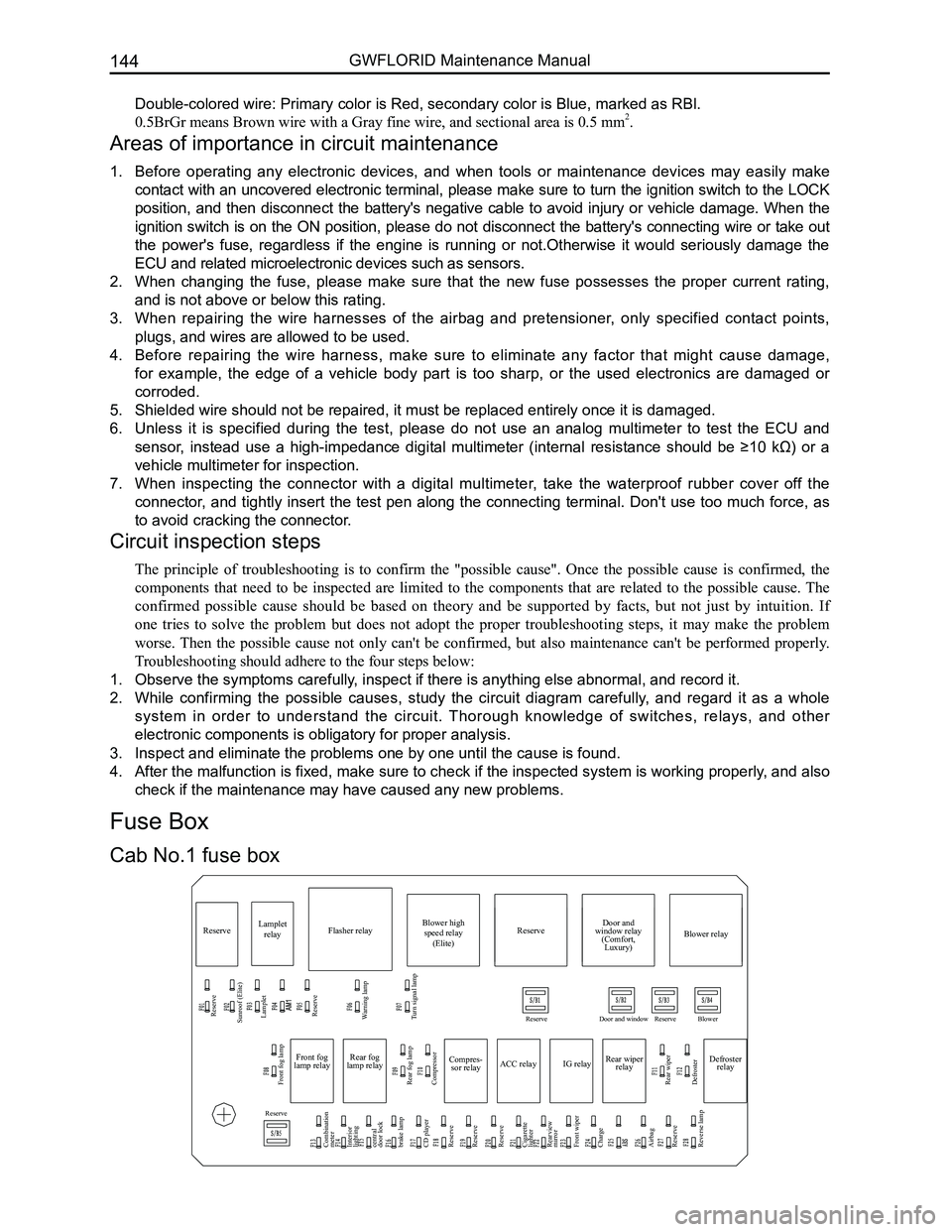
Cab No.1 fuse box
Fuse Box
Page 155 of 281
Downloaded from www.Manualslib.com manuals search engine GWFLORID Maintenance Manual148
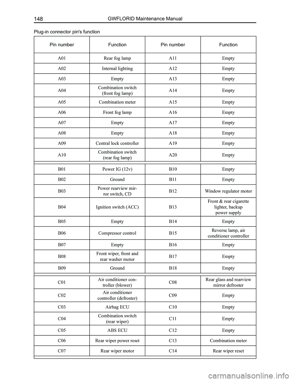
Plug-in connector pin's function
Pin numberFunctionPin numberFunction
A01Rear fog lampA11Empty
A02Internal lightingA12Empty
A03EmptyA13Empty
A04Combination switch
(front fog lamp)A14Empty
A05Combination meter A15Empty
A06Front fog lampA16Empty
A07EmptyA17Empty
A08EmptyA18Empty
A09Central lock controllerA19Empty
A10Combination switch
(rear fog lamp)A20Empty
B01Power IG (12v)B10Empty
B02GroundB11Empty
B03Power rearview mir-
ror switch, CDB12Window regulator motor
B04Ignition switch (ACC)B13
Front & rear cigarette
lighter, backup
power supply
B05EmptyB14Empty
B06Compressor controlB15Reverse lamp, air
conditioner controller
B07EmptyB16Empty
B08Front wiper, front and
rear washer motorB17Empty
B09GroundB18Empty
C01Air conditioner con-
troller (blower) C08Rear glass and rearview
mirror defroster
C02Air conditioner
controller (defroster) C09Empty
C03Airbag ECU C10Empty
C04Combination switch
(rear wiper) C11Empty
C05ABS ECUC12Empty
C06Rear wiper power resetC13Combination meter
C07Rear wiper motorC14Rear wiper reset
Page 156 of 281
Downloaded from www.Manualslib.com manuals search engine 149Vehicle Body Electronic System
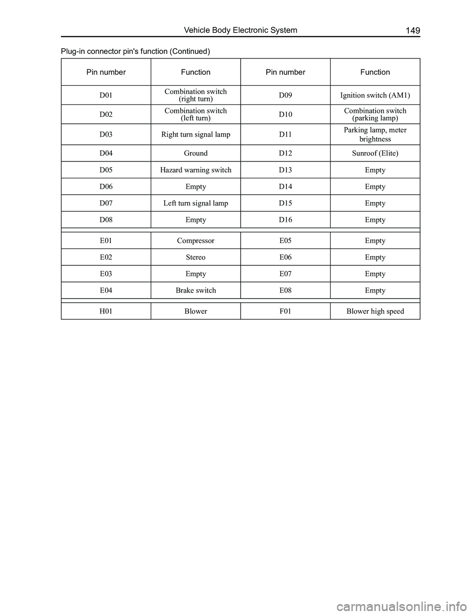
Plug-in connector pin's function (Continued)
Pin numberFunctionPin numberFunction
D01Combination switch (right turn)D09Ignition switch (AM1)
D02Combination switch (left turn)D10Combination switch (parking lamp)
D03Right turn signal lampD11Parking lamp, meter
brightness
D04GroundD12Sunroof (Elite)
D05Hazard warning switchD13Empty
D06EmptyD14Empty
D07Left turn signal lampD15Empty
D08EmptyD16Empty
E01CompressorE05Empty
E02StereoE06Empty
E03EmptyE07Empty
E04Brake switchE08Empty
H01BlowerF01Blower high speed