washer fluid GREAT WALL FLORID 2008 Service Manual
[x] Cancel search | Manufacturer: GREAT WALL, Model Year: 2008, Model line: FLORID, Model: GREAT WALL FLORID 2008Pages: 281, PDF Size: 43.97 MB
Page 16 of 281
Downloaded from www.Manualslib.com manuals search engine 9Overview
General Repair Methods and Operations
1. If a jack is needed, please kindly comply to the safety procedures liste\
d below.
2. Park the vehicle on a flat surface, stablize the front and the back wheels using any fixed object or tool,
jack up the vehicle, support it with the chassis, and then start the mai\
ntenance.
3. Disconnect the battery's negative cable before maintenance, in order to reduce the possibility of
damaging and burning out the cable due to a short circuit.
4. Cover the vehicle body, seats, and floor to prevent them from being damaged and polluted.
5. Handle brake fluid and antifreeze fluid carefully, because it may damage the vehicle's surface paint
and its surroundings.
6. Using the proper tools or basic tools that have been recommended and are purchasable is very
important in guaranteeing an effective and reliable maintenance result.
7. Dispose the used dowel pins, gaskets, O-rings, oil seals, lock washers, and self-locking nuts. Prepare
new parts for installation. Normal functions are not guaranteed if these\
parts are reused.
8. Store the removed parts in order and in groups to make reassembly more c\
onvenient.
9. Store bolts and nuts separately, because their hardness levels and designs are different according to
the installation locations.
10. Clean parts before they are inspected or reassembled. In addition, parts that come in contact with
engine oil also need to be cleaned, as well as checked for blockage by u\
sing compressed air.
11. Before installation, use engine oil or grease to lubricate the rotating and sliding sides of the necessary
parts.
12. When necessary, use sealant on gaskets to avoid leakage.
13. Please carefully comply to all tightening torque specifications of b\
olts and nuts.
14. After maintenance, check to make sure whether the repairs were performed correctly and whether the
malfunctions have been fixed.
Vehicle Lifting/Lowering Procedures
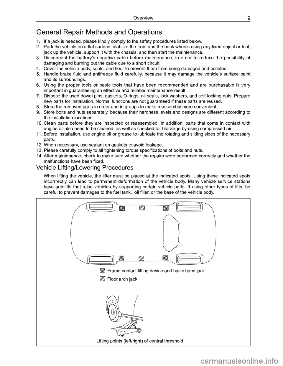
When lifting the vehicle, the lifter must be placed at the indicated spots. Using these indicated spots
incorrrectly can lead to permanent deformation of the vehicle body. Many vehicle service stations
have autolifts that raise vehicles by supporting certain vehicle parts. If using other types of lifts, be
careful to prevent damages to the fuel tank, oil filler, or the base of the vehicle body.
Frame contact lifting device and basic hand jack
Floor arch jack
Lifting points (left/right) of central threshold
Page 25 of 281
Downloaded from www.Manualslib.com manuals search engine GWFLORID Maintenance Manual18
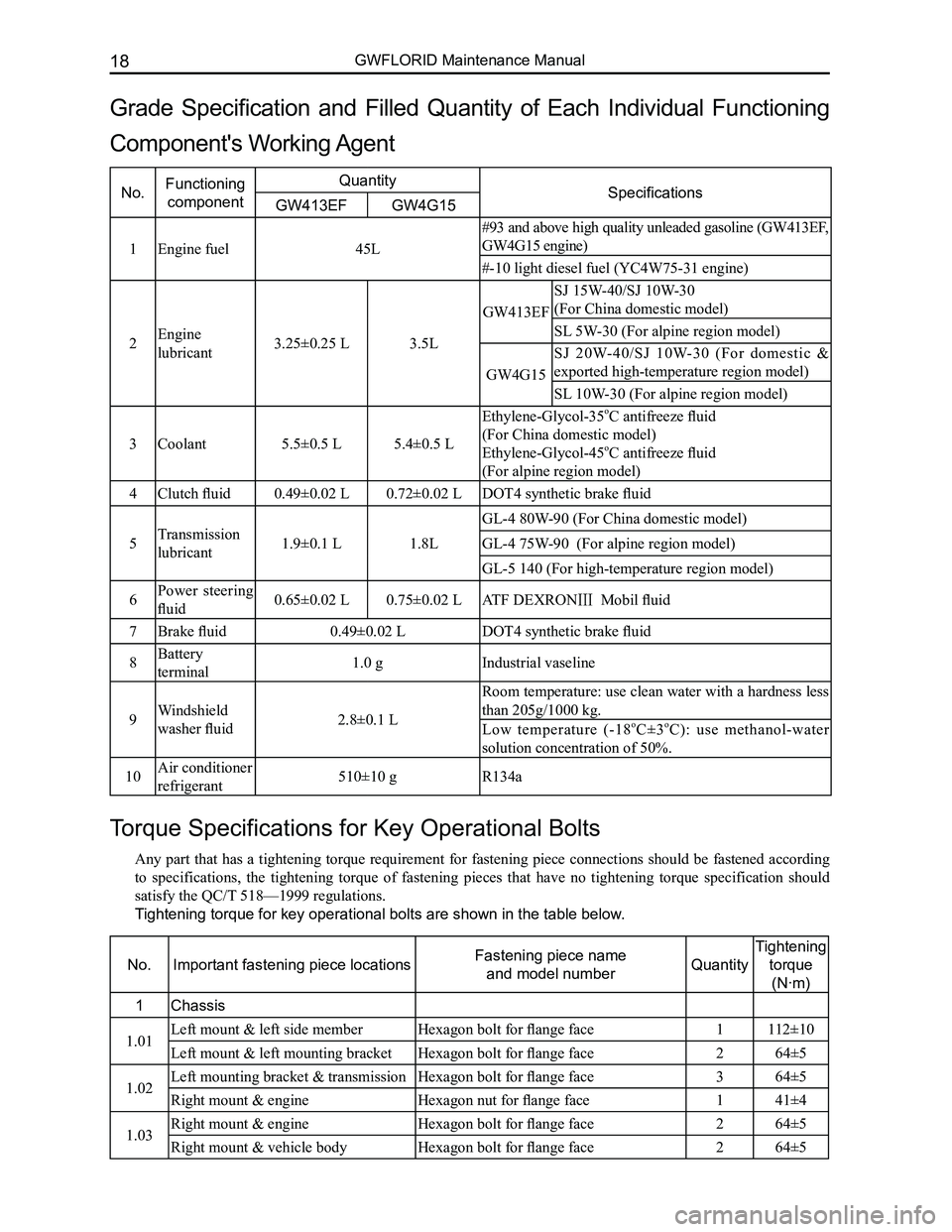
Torque Specifications for Key Operational Bolts
Any part that has a tightening torque requirement for fastening piece connections should be fastened according
to specifications, the tightening torque of fastening pieces that have no tightening torque specification should
satisfy the QC/T 518—1999 regulations.
Tightening torque for key operational bolts are shown in the table below.
No.Important fastening piece locationsFastening piece name
and model numberQuantity
Tightening
torque
(N·m)
1Chassis
1.01Left mount & left side memberHexagon bolt for flange face1112±10
Left mount & left mounting bracketHexagon bolt for flange face264±5
1.02Left mounting bracket & transmissionHexagon bolt for flange face364±5
Right mount & engineHexagon nut for flange face141±4
1.03Right mount & engineHexagon bolt for flange face264±5
Right mount & vehicle bodyHexagon bolt for flange face 264±5
Grade Specification and Filled Quantity of Each Individual Functioning
Component's Working Agent
No.Functioning
component
QuantitySpecificationsGW413EFGW4G15
1Engine fuel45L
#93 and above high quality unleaded gasoline (GW413EF,
GW4G15 engine)
#-10 light diesel fuel (YC4W75-31 engine)
2Engine
lubricant3.25±0.25 L3.5L
GW413EF
SJ 15W-40/SJ 10W-30
(For China domestic model)
SL 5W-30 (For alpine region model)
GW4G15
SJ 20W-40/SJ 10W-30 (For domestic &
exported high-temperature region model)
SL 10W-30 (For alpine region model)
3Coolant5.5±0.5 L5.4±0.5 L
Ethylene-Glycol-35oC antifreeze fluid
(For China domestic model)
Ethylene-Glycol-45oC antifreeze fluid
(For alpine region model)
4Clutch fluid0.49±0.02 L0.72±0.02 LDOT4 synthetic brake fluid
5Transmission
lubricant1.9±0.1 L1.8L
GL-4 80W-90 (For China domestic model)
GL-4 75W-90 (For alpine region model)
GL-5 140 (For high-temperature region model)
6Power steering
fluid0.65±0.02 L0.75±0.02 LATF DEXRONⅢ Mobil fluid
7Brake fluid0.49±0.02 LDOT4 synthetic brake fluid
8Battery
terminal1.0 gIndustrial vaseline
9Windshield
washer fluid2.8±0.1 L
Room temperature: use clean water with a hardness less
than 205g/1000 kg.
Low temperature (-18oC±3oC): use methanol-water
solution concentration of 50%.
10Air conditioner
refrigerant510±10 gR134a
Page 115 of 281
Downloaded from www.Manualslib.com manuals search engine GWFLORID Maintenance Manual108
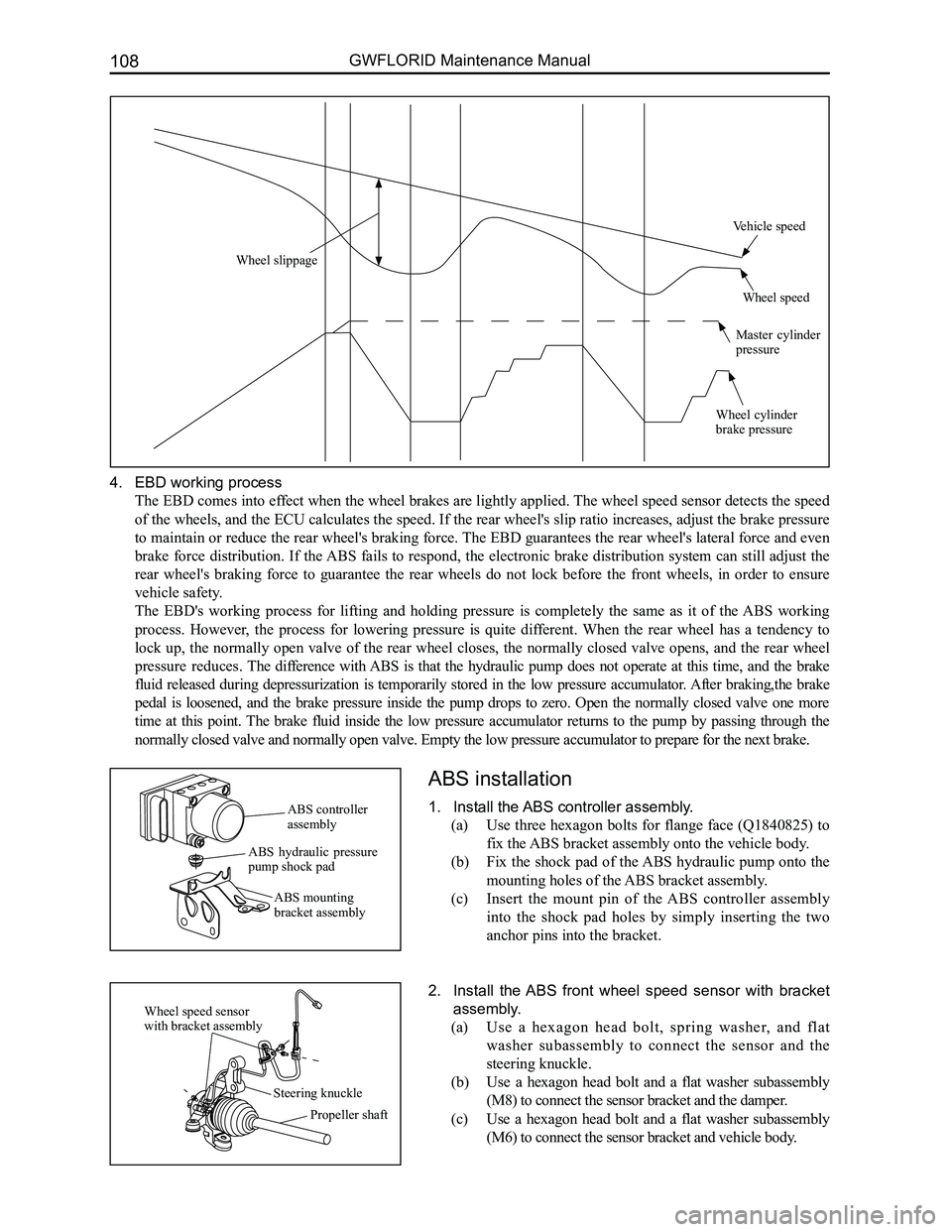
4. EBD working process
The EBD comes into effect when the wheel brakes are lightly applied. The wheel speed sensor detects the speed
of the wheels, and the ECU calculates the speed. If the rear wheel's slip ratio increases, adjust the brake pressure
to maintain or reduce the rear wheel's braking force. The EBD guarantees the rear wheel's lateral force and even
brake force distribution. If the ABS fails to respond, the electronic brake distribution system can still adjust the
rear wheel's braking force to guarantee the rear wheels do not lock before the front wheels, in order to ensure
vehicle safety.
The EBD's working process for lifting and holding pressure is completely the same as it of the ABS working
process. However, the process for lowering pressure is quite different. When the rear wheel has a tendency to
lock up, the normally open valve of the rear wheel closes, the normally closed valve opens, and the rear wheel
pressure reduces. The difference with ABS is that the hydraulic pump does not operate at this time, and the brake
fluid released during depressurization is temporarily stored in the low pressure accumulator. After braking,the brake
pedal is loosened, and the brake pressure inside the pump drops to zero. Open the normally closed valve one more
time at this point. The brake fluid inside the low pressure accumulator returns to the pump by passing through the
normally closed valve and normally open valve. Empty the low pressure ac\
cumulator to prepare for the next brake.
ABS installation
1. Install the ABS controller assembly.
(a) Use three hexagon bolts for flange face (Q1840825) to
fix the ABS bracket assembly onto the vehicle body.
(b) Fix the shock pad of the ABS hydraulic pump onto the
mounting holes of the ABS bracket assembly.
(c) Insert the mount pin of the ABS controller assembly
into the shock pad holes by simply inserting the two
anchor pins into the bracket.
2. Install the ABS front wheel speed sensor with bracket
assembly.
(a) Use a hexagon head bolt, spring washer, and flat
washer subassembly to connect the sensor and the
steering knuckle.
(b) Use a hexagon head bolt and a flat washer subassembly
(M8) to connect the sensor bracket and the damper.
(c) Use a hexagon head bolt and a flat washer subassembly
(M6) to connect the sensor bracket and vehicle body.
ABS controller assembly
ABS hydraulic pressure pump shock pad
ABS mounting bracket assembly
Wheel speed sensor with bracket assembly
Steering knuckle
Propeller shaft
Wheel slippage
Vehicle speed
Wheel speed
Master cylinder pressure
Wheel cylinder brake pressure
Page 131 of 281
Downloaded from www.Manualslib.com manuals search engine GWFLORID Maintenance Manual124
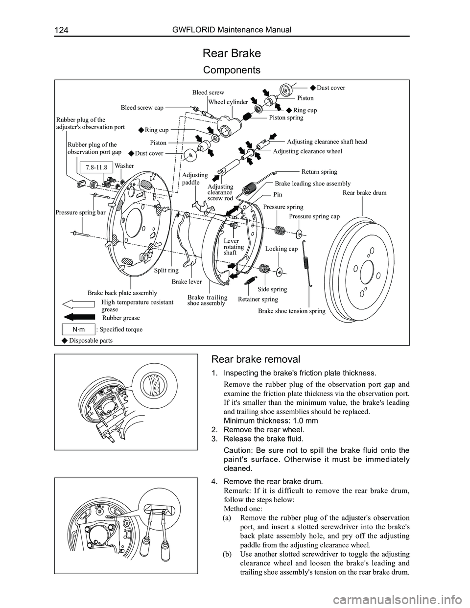
Rear Brake
Components
4. Remove the rear brake drum.
Remark: If it is difficult to remove the rear brake drum,
follow the steps below:
Method one:
(a) Remove the rubber plug of the adjuster's observation
port, and insert a slotted screwdriver into the brake's
back plate assembly hole, and pry off the adjusting
paddle from the adjusting clearance wheel.
(b) Use another slotted screwdriver to toggle the adjusting
clearance wheel and loosen the brake's leading and
trailing shoe assembly's tension on the rear brake drum.
Disposable parts
Dust cover
Brake leading shoe assembly
Pressure spring
Pressure spring cap
Brake shoe tension spring
Rear brake drum
Lever rotating shaft
Retainer spring
Locking cap
Split ring
Brake lever
Brake trailing shoe assembly
Brake back plate assembly
Pressure spring bar
Rubber plug of the adjuster's observation port
Rubber plug of the observation port gap
Washer
Bleed screw cap
Bleed screwPiston
Ring cup
Piston spring
Wheel cylinder
Adjusting clearance shaft head
Adjusting clearance wheel
Adjusting clearance screw rod
Return springAdjusting paddle
Pin
Side spring
Dust cover
Piston
Ring cup
Rubber grease
: Specified torqueN·m
7.8-11.8
High temperature resistant grease
Rear brake removal
1. Inspecting the brake's friction plate thickness.
Remove the rubber plug of the observation port gap and
examine the friction plate thickness via the observation port.
If it's smaller than the minimum value, the brake's leading
and trailing shoe assemblies should be replaced.
Minimum thickness: 1.0 mm
2. Remove the rear wheel.
3. Release the brake fluid.
Caution: Be sure not to spill the brake fluid onto the
paint's surface. Otherwise it must be immediately
cleaned.
Page 159 of 281
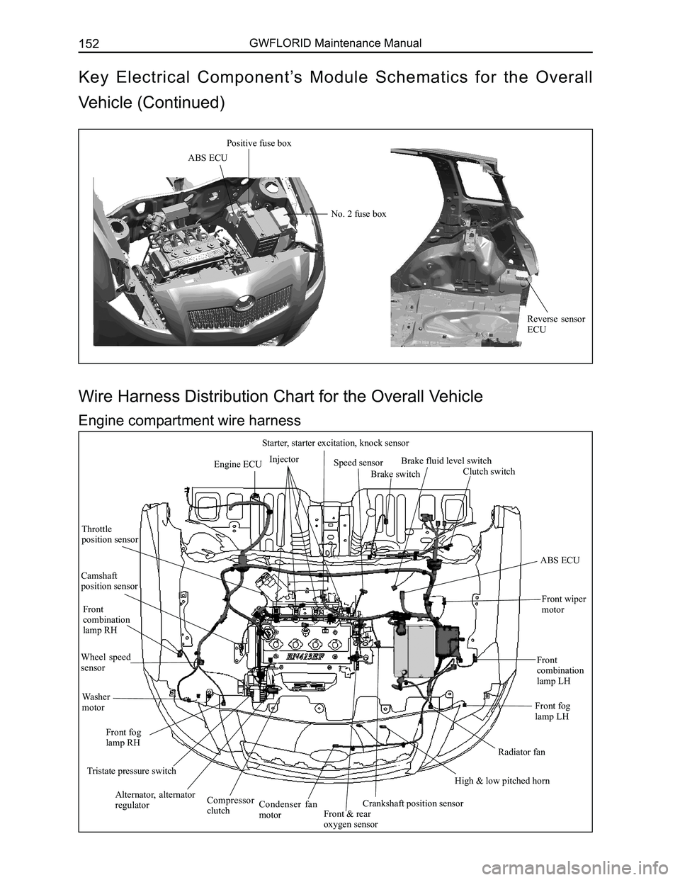
Downloaded from www.Manualslib.com manuals search engine GWFLORID Maintenance Manual152
Engine ECUInjector
Starter, starter excitation, knock sensor
Speed sensor
Brake switch
Brake fluid level switch
Clutch switch
ABS ECU
Front wiper
motor
Front combination lamp LH
Front fog lamp LH
Radiator fan
High & low pitched horn
Crankshaft position sensorFront & rear oxygen sensor
Condenser fan motor
Compressor clutch
Alternator, alternator regulator
Tristate pressure switch
Front fog lamp RH
Washer motor
Wheel speed sensor
Front combination lamp RH
Camshaft position sensor
Throttle position sensor
Wire Harness Distribution Chart for the Overall Vehicle
Engine compartment wire harness
ABS ECU
Positive fuse box
No. 2 fuse box
Reverse sensor ECU
Key Electrical Component’s Module Schematics for the Overall
Vehicle (Continued)
Page 162 of 281
Downloaded from www.Manualslib.com manuals search engine 155Vehicle Body Electronic System
Condenser fan motor
Connected compressor
Oil pressure switch
Front oxygen sensor
Connected reverse switch
Connected engine speed sensor Connected
ignition coil
Connected speed sensor Connected coolant temp. sensor
Canister control valve
Connected combination meter A
Connected antenna
Diagnostic port
Connected AC switch Connected air conditioner temperature sensor
Front passenger side airbag
Connected speed adjustive resistance, blower
Front window regulator RH
Front window regulator switch RH
Front medium woofer RH
Front tweeter LH Right outer electric mirror
Front passenger side central door lock switch
Front door lamp switch RH
Front passenger seat belt pretensioner Front door lock motor RH
Ground
plate 3
Connected cigarette lighter (lighting)
Connected cigarette lighter
Front passenger seat belt switch
Connected parking brake switch Connected air conditioner governor & front
passenger seat belt unfastened indicator lamp
Connected CD player
Connected engine ECUConnected ground P1#
Connected ground P2#
Connected starter
Connected knock sensor
Connected starter field coil
Connected inlet
temperature pressure
sensor
connected
electronic throttle
Rear oxygen sensor
Connected 4th
cylinder injection
nozzle
Connected 3rd
cylinder injection
nozzle
Connected 2nd
cylinder injection
nozzle
Connected 1st
cylinder
injection nozzle
Connected generator
Connected engine armature Connected front combination lamp RH
Connected front fog lamp RH
Connected rear washer motor
Connected front washer motor
Connected front wheel speed sensor RH
Right ground
Connected A/C pressure switch
Connected phase sensor
Connected low
pitched horn
Connected front
combination lamp LH
Rediator fan motor
Connected front
fog lamp LH
Connected high pitched horn
Battery
negative
Body
ground
Battery
Left ground Connected
brake lamp
switch Connected brake fluid warning switch
Connected theft deterrent indicator Theft deterrent ECU 1Connected lock
cylinder lightConnected ignition
switch (white)
The key is inserted into the switch
Right combination switch (wiper) Connected airbag ECU (yellow)Ground
plate 2
Ground
plate 4
Connected accelerator pedal
Ground plate 1
Left outer electric mirror
Front medium woofer LH Front door lock motor LH
Rear medium woofer LH
Rear window regulator switch LH
Rear door lock motor LH Rear door lamp switch LH
Ground point ACapacitor
Vehicle power supply
Rear fog lamp LH Left license plate lamp
High mounted brake lamp
Ground point Trunk opener switch
Trunk motorRear wiper motor
Rear windshield defroster “-”
Trunk lamp switch Right license plate lamp
Rear fog lamp RH
Rear combination lamp RHRear wheel speed sensor RH
Rear window
regulator RH
Rear window
regulator switch RH
Rear door lock motor RH
Rear door lamp switch RH Rear medium woofer RH
Ground point B
Rear combination lamp LH
Rear windshield defroster “+”
Rear wheel speed
sensor LH
Rear window regulator LH
Fuel pump, fuel sensor
Rear interior dome lamp
Front door lamp
switch LH
Driver seat belt pretensioner Driver seat belt switch
Front tweeter LH
Connected light brightness regulator switch
Connected rearview mirror switch (white)
Connected glove box lamp
Front window regulator LH Left combination switch (light)
Connected main airbag, horn switch
Window regulator mainly
control switch, central door
lock mainly control switch Connected central door lock controller (white)
Connected front wiper motor
Connected clutch
switch
Connected ABS ECUBattery
positive
Connected front wheel
speed sensor LH Engine groud
Starter connect to
battery positive
Generator connect to
battery positive
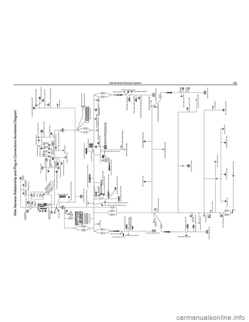
Wire Harness Relationship and Plug-in Connections Numbered Diagram