key battery GREAT WALL FLORID 2008 Service Manual
[x] Cancel search | Manufacturer: GREAT WALL, Model Year: 2008, Model line: FLORID, Model: GREAT WALL FLORID 2008Pages: 281, PDF Size: 43.97 MB
Page 25 of 281
Downloaded from www.Manualslib.com manuals search engine GWFLORID Maintenance Manual18
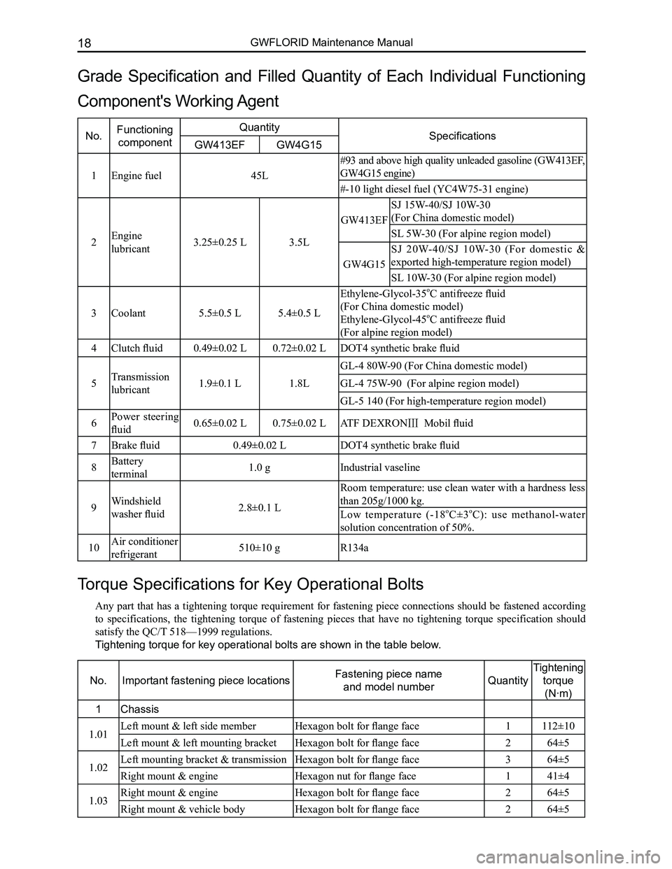
Torque Specifications for Key Operational Bolts
Any part that has a tightening torque requirement for fastening piece connections should be fastened according
to specifications, the tightening torque of fastening pieces that have no tightening torque specification should
satisfy the QC/T 518—1999 regulations.
Tightening torque for key operational bolts are shown in the table below.
No.Important fastening piece locationsFastening piece name
and model numberQuantity
Tightening
torque
(N·m)
1Chassis
1.01Left mount & left side memberHexagon bolt for flange face1112±10
Left mount & left mounting bracketHexagon bolt for flange face264±5
1.02Left mounting bracket & transmissionHexagon bolt for flange face364±5
Right mount & engineHexagon nut for flange face141±4
1.03Right mount & engineHexagon bolt for flange face264±5
Right mount & vehicle bodyHexagon bolt for flange face 264±5
Grade Specification and Filled Quantity of Each Individual Functioning
Component's Working Agent
No.Functioning
component
QuantitySpecificationsGW413EFGW4G15
1Engine fuel45L
#93 and above high quality unleaded gasoline (GW413EF,
GW4G15 engine)
#-10 light diesel fuel (YC4W75-31 engine)
2Engine
lubricant3.25±0.25 L3.5L
GW413EF
SJ 15W-40/SJ 10W-30
(For China domestic model)
SL 5W-30 (For alpine region model)
GW4G15
SJ 20W-40/SJ 10W-30 (For domestic &
exported high-temperature region model)
SL 10W-30 (For alpine region model)
3Coolant5.5±0.5 L5.4±0.5 L
Ethylene-Glycol-35oC antifreeze fluid
(For China domestic model)
Ethylene-Glycol-45oC antifreeze fluid
(For alpine region model)
4Clutch fluid0.49±0.02 L0.72±0.02 LDOT4 synthetic brake fluid
5Transmission
lubricant1.9±0.1 L1.8L
GL-4 80W-90 (For China domestic model)
GL-4 75W-90 (For alpine region model)
GL-5 140 (For high-temperature region model)
6Power steering
fluid0.65±0.02 L0.75±0.02 LATF DEXRONⅢ Mobil fluid
7Brake fluid0.49±0.02 LDOT4 synthetic brake fluid
8Battery
terminal1.0 gIndustrial vaseline
9Windshield
washer fluid2.8±0.1 L
Room temperature: use clean water with a hardness less
than 205g/1000 kg.
Low temperature (-18oC±3oC): use methanol-water
solution concentration of 50%.
10Air conditioner
refrigerant510±10 gR134a
Page 162 of 281
Downloaded from www.Manualslib.com manuals search engine 155Vehicle Body Electronic System
Condenser fan motor
Connected compressor
Oil pressure switch
Front oxygen sensor
Connected reverse switch
Connected engine speed sensor Connected
ignition coil
Connected speed sensor Connected coolant temp. sensor
Canister control valve
Connected combination meter A
Connected antenna
Diagnostic port
Connected AC switch Connected air conditioner temperature sensor
Front passenger side airbag
Connected speed adjustive resistance, blower
Front window regulator RH
Front window regulator switch RH
Front medium woofer RH
Front tweeter LH Right outer electric mirror
Front passenger side central door lock switch
Front door lamp switch RH
Front passenger seat belt pretensioner Front door lock motor RH
Ground
plate 3
Connected cigarette lighter (lighting)
Connected cigarette lighter
Front passenger seat belt switch
Connected parking brake switch Connected air conditioner governor & front
passenger seat belt unfastened indicator lamp
Connected CD player
Connected engine ECUConnected ground P1#
Connected ground P2#
Connected starter
Connected knock sensor
Connected starter field coil
Connected inlet
temperature pressure
sensor
connected
electronic throttle
Rear oxygen sensor
Connected 4th
cylinder injection
nozzle
Connected 3rd
cylinder injection
nozzle
Connected 2nd
cylinder injection
nozzle
Connected 1st
cylinder
injection nozzle
Connected generator
Connected engine armature Connected front combination lamp RH
Connected front fog lamp RH
Connected rear washer motor
Connected front washer motor
Connected front wheel speed sensor RH
Right ground
Connected A/C pressure switch
Connected phase sensor
Connected low
pitched horn
Connected front
combination lamp LH
Rediator fan motor
Connected front
fog lamp LH
Connected high pitched horn
Battery
negative
Body
ground
Battery
Left ground Connected
brake lamp
switch Connected brake fluid warning switch
Connected theft deterrent indicator Theft deterrent ECU 1Connected lock
cylinder lightConnected ignition
switch (white)
The key is inserted into the switch
Right combination switch (wiper) Connected airbag ECU (yellow)Ground
plate 2
Ground
plate 4
Connected accelerator pedal
Ground plate 1
Left outer electric mirror
Front medium woofer LH Front door lock motor LH
Rear medium woofer LH
Rear window regulator switch LH
Rear door lock motor LH Rear door lamp switch LH
Ground point ACapacitor
Vehicle power supply
Rear fog lamp LH Left license plate lamp
High mounted brake lamp
Ground point Trunk opener switch
Trunk motorRear wiper motor
Rear windshield defroster “-”
Trunk lamp switch Right license plate lamp
Rear fog lamp RH
Rear combination lamp RHRear wheel speed sensor RH
Rear window
regulator RH
Rear window
regulator switch RH
Rear door lock motor RH
Rear door lamp switch RH Rear medium woofer RH
Ground point B
Rear combination lamp LH
Rear windshield defroster “+”
Rear wheel speed
sensor LH
Rear window regulator LH
Fuel pump, fuel sensor
Rear interior dome lamp
Front door lamp
switch LH
Driver seat belt pretensioner Driver seat belt switch
Front tweeter LH
Connected light brightness regulator switch
Connected rearview mirror switch (white)
Connected glove box lamp
Front window regulator LH Left combination switch (light)
Connected main airbag, horn switch
Window regulator mainly
control switch, central door
lock mainly control switch Connected central door lock controller (white)
Connected front wiper motor
Connected clutch
switch
Connected ABS ECUBattery
positive
Connected front wheel
speed sensor LH Engine groud
Starter connect to
battery positive
Generator connect to
battery positive
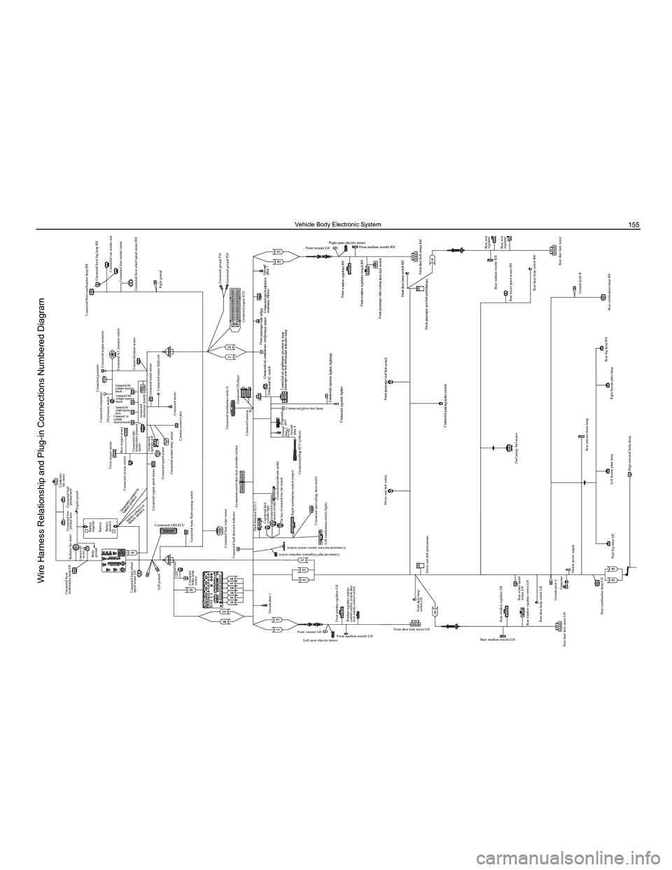
Wire Harness Relationship and Plug-in Connections Numbered Diagram
Page 190 of 281
Downloaded from www.Manualslib.com manuals search engine 183Electrical Accessories
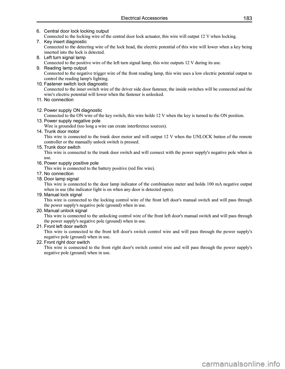
6. Central door lock locking output
Connected to the locking wire of the central door lock actuator, this wire will output 12 V when locking.
7. Key insert diagnostic
Connected to the detecting wire of the lock head, the electric potential of this wire will lower when a key being
inserted into the lock is detected.
8. Left turn signal lamp
Connected to the positive wire of the left turn signal lamp, this wire o\
utputs 12 V during its use.
9. Reading lamp output
Connected to the negative trigger wire of the front reading lamp, this wire uses a low electric potential output to
control the reading lamp's lighting.
10. Fastener switch lock diagnostic
Connected to the inner switch wire of the driver side door fastener, the inside switches will be connected and the
wire's electric potential will lower when the fastener is unlocked.
11. No connection
12. Power supply ON diagnostic
Connected to the ON wire of the key switch, this wire holds 12 V when the key is turned to the ON position.
13. Power supply negative pole
Wire is grounded (too long a wire can create interference sources).
14. Trunk door motor
This wire is connected to the trunk door motor and will output 12 V when the UNLOCK button of the remote
controller or the manually unlock switch is pressed.
15. Trunk door switch
This wire is connected to the trunk door switch and will connect with the power supply's negative pole when in
use.
16. Power supply positive pole
This wire is connected to the battery positive (red fire wire).
17. No connection
18. Door lamp signal
This wire is connected to the door lamp indicator of the combination meter and holds 100 mA negative output
when in use (the indicator light is on when any door is detected open)\
.
19. Manual lock signal
This wire is connected to the locking control wire of the front left door's manual switch and will pass through
the power supply's negative pole (ground) when in use.
20. Manual unlock signal
This wire is connected to the unlocking control wire of the front left door's manual switch and will pass through
the power supply's negative pole (ground) when in use.
21. Front left door switch
This wire is connected to the front left door's switch control wire and will pass through the power supply's
negative pole (ground) when in use.
22. Front right door switch
This wire is connected to the front right door's switch control wire and will pass through the power supply's
negative pole (ground) when in use.
Page 195 of 281
Downloaded from www.Manualslib.com manuals search engine GWFLORID Maintenance Manual188
not necessarily mean that engine start failure is due to a immobilizer system malfunction. The reasons for start-
ing engine failures are numerous, including factors like fuel, gas, fire, electricity, wires, etc. If the engine cannot
start, first check if the immobilizer system is working normally. This can be judged by looking at the flashing
theft deterrent indicator lamp which is located on the dashboard in front of the driver seat: Insert the key into the
lock cylinder and turn it to the "ON" position. If a legal key is used to start the engine, once the warning lamp is
connected to the ON end and the transponder is confirmed, the LED will remain unlit. Then when the ON end is
disconnected and the key is pulled out, the LED will shine for 0.25 s and darken for 4 s, as to act as a warning.
If an illegal key is used to start up the engine or there is something wrong with the system, the alarm indicator
lamp will shine for 0.25 s and darken for 4 s. If all is normal, then check the other parts of the engine. If abnor-
mal, first perform immobilizer system troubleshooting. A scanner can be used to judge if the immobilizer system
is working normally, but the precondition is that the scanner must be able to establish communication with the
theft deterrent controller.
1. If communication cannot be established, consider the following:
(a) Check whether the battery voltage is higher than 9 V
(b) Check whether the scanner plug is well contacted to the vehicle socket
(c) Use a multimeter to check whether the 7 pin of the OBD-II plug (diagnostic plug) is connected to the theft
deterrent controller's A7 pin
(d) Check whether the power supply of the theft deterrent controller is normal. (Use a multimeter to measure
whether the voltage of the theft deterrent controller's socket A1 pin and A2 pin is higher than 9 V)
(e) Then adopt the substitution method, which is to replace the theft deterrent controller to check if there is
anything wrong with the theft deterrent controller.
• If the failure is related to the theft deterrent controller, change it and initiate re-matching.
• If the failure has nothing to do with the theft deterrent controller, remove the electronic controller which
is connected to the alarm's K wire, such as the ABS controller, engine electrojet controller, airbag ECU
assembly, etc., as to ascertain if the present fault is caused by the wire harness connected with the theft
deterrent controller's K wire.
2. If communication can be established
Connect the scanner to the vehicle diagnostic port. Insert the key into the steering lock, and turn it to the "ON"
position, then select the scanner to check the immobilizer system's trou\
ble code.
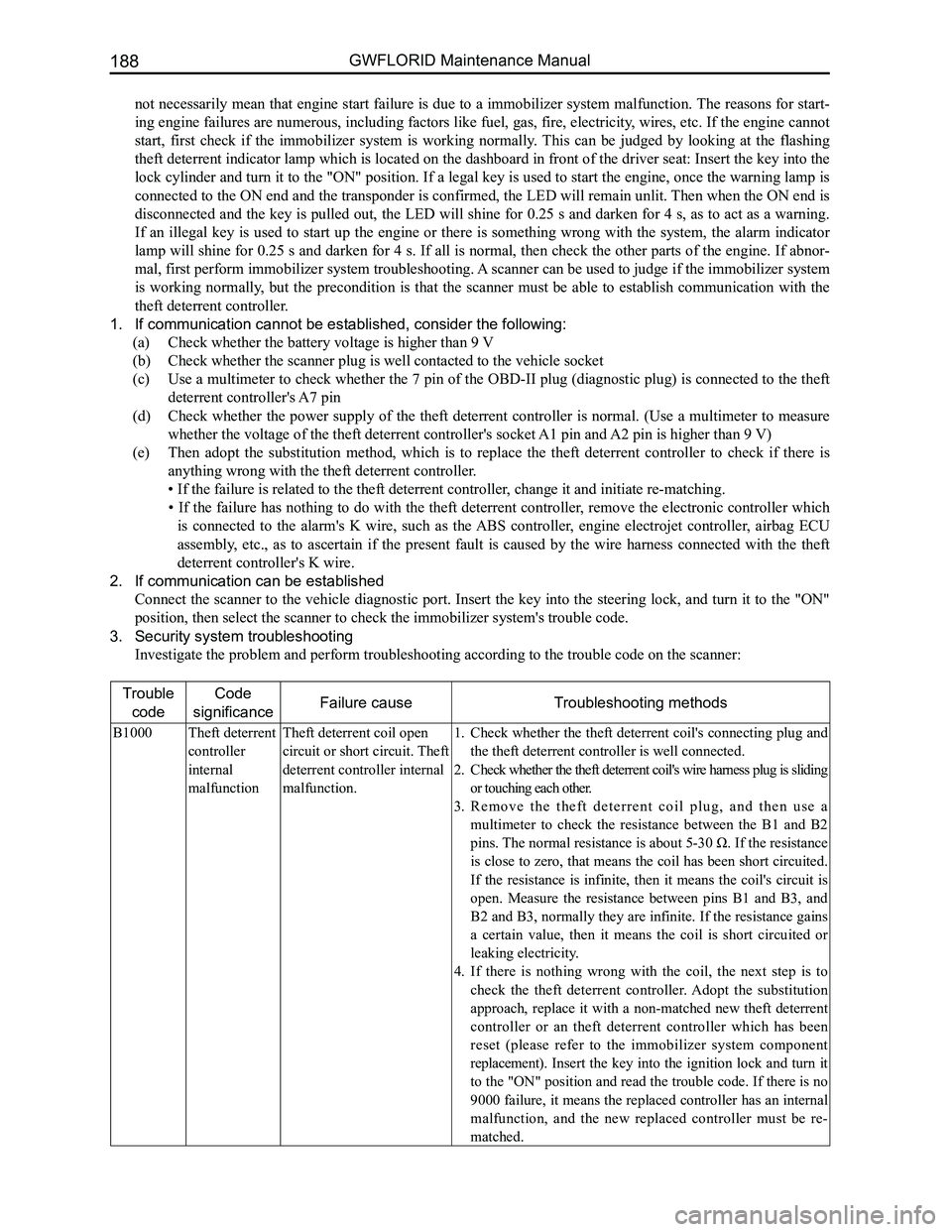
3. Security system troubleshooting
Investigate the problem and perform troubleshooting according to the tro\
uble code on the scanner:
Trouble
code
Code
significanceFailure causeTroubleshooting methods
B1000Theft deterrent
controller
internal
malfunction
Theft deterrent coil open
circuit or short circuit. Theft
deterrent controller internal
malfunction.
Check whether the theft deterrent coil's connecting plug and 1.
the theft deterrent controller is well connected.
Check whether the theft deterrent coil's wire harness plug is sliding 2.
or touching each other.
R e m o v e t h e t h e f t d e t e r r e n t c o i l p l u g , a n d t h e n u s e a 3.
multimeter to check the resistance between the B1 and B2
pins. The normal resistance is about 5-30 Ω. If the resistance
is close to zero, that means the coil has been short circuited.
If the resistance is infinite, then it means the coil's circuit is
open. Measure the resistance between pins B1 and B3, and
B2 and B3, normally they are infinite. If the resistance gains
a certain value, then it means the coil is short circuited or
leaking electricity.
If there is nothing wrong with the coil, the next step is to 4.
check the theft deterrent controller. Adopt the substitution
approach, replace it with a non-matched new theft deterrent
controller or an theft deterrent controller which has been
reset (please refer to the immobilizer system component
replacement). Insert the key into the ignition lock and turn it
to the "ON" position and read the trouble code. If there is no
9000 failure, it means the replaced controller has an internal
malfunction, and the new replaced controller must be re-
matched.
Page 197 of 281
Downloaded from www.Manualslib.com manuals search engine GWFLORID Maintenance Manual190
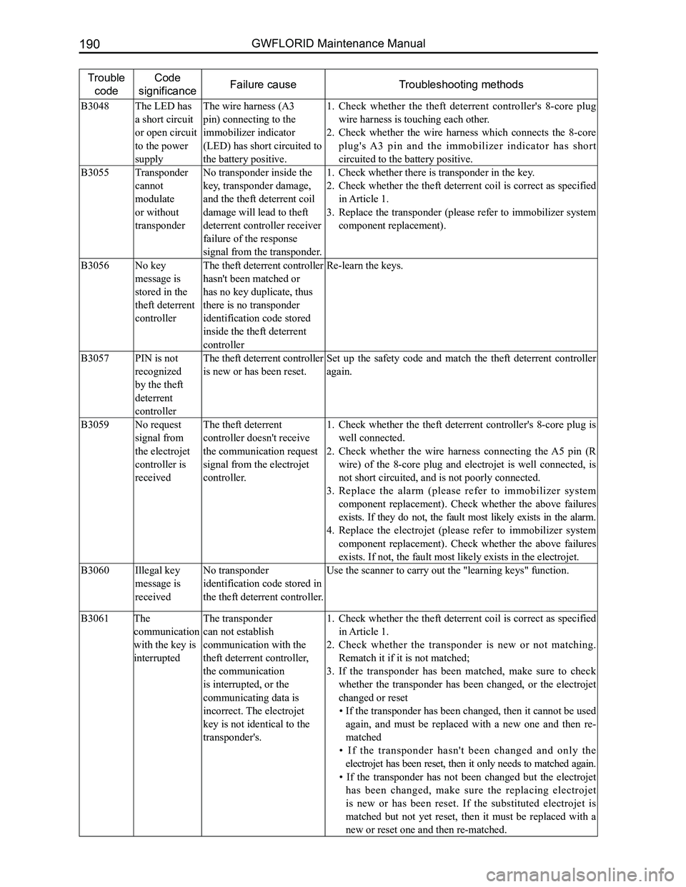
Trouble
code
Code
significanceFailure causeTroubleshooting methods
B3048The LED has
a short circuit
or open circuit
to the power
supply
The wire harness (A3
pin) connecting to the
immobilizer indicator
(LED) has short circuited to
the battery positive.
Check whether the theft deterrent controller's 8-core plug 1.
wire harness is touching each other.
Check whether the wire harness which connects the 8-core 2.
plug's A3 pin and the immobilizer indicator has short
circuited to the battery positive.
B3055Transponder
cannot
modulate
or without
transponder
No transponder inside the
key, transponder damage,
and the theft deterrent coil
damage will lead to theft
deterrent controller receiver
failure of the response
signal from the transponder.
Check whether there is transponder in the key.1.
Check whether the theft deterrent coil is correct as specified 2.
in Article 1.
Replace the transponder (please refer to immobilizer system 3.
component replacement).
B3056No key
message is
stored in the
theft deterrent
controller
The theft deterrent controller
hasn't been matched or
has no key duplicate, thus
there is no transponder
identification code stored
inside the theft deterrent
controller
Re-learn the keys.
B3057PIN is not
recognized
by the theft
deterrent
controller
The theft deterrent controller
is new or has been reset.
Set up the safety code and match the theft deterrent controller
again.
B3059No request
signal from
the electrojet
controller is
received
The theft deterrent
controller doesn't receive
the communication request
signal from the electrojet
controller.
Check whether the theft deterrent controller's 8-core plug is 1.
well connected.
Check whether the wire harness connecting the A5 pin (R 2.
wire) of the 8-core plug and electrojet is well connected, is
not short circuited, and is not poorly connected.
Replace the alarm (please refer to immobilizer system 3.
component replacement). Check whether the above failures
exists. If they do not, the fault most likely exists in the alarm.
Replace the electrojet (please refer to immobilizer system 4.
component replacement). Check whether the above failures
exists. If not, the fault most likely exists in the electrojet.
B3060Illegal key
message is
received
No transponder
identification code stored in
the theft deterrent controller.
Use the scanner to carry out the "learning keys" function.
B3061The
communication
with the key is
interrupted
The transponder
can not establish
communication with the
theft deterrent controller,
the communication
is interrupted, or the
communicating data is
incorrect. The electrojet
key is not identical to the
transponder's.
Check whether the theft deterrent coil is correct as specified 1.
in Article 1.
Check whether the transponder is new or not matching. 2.
Rematch it if it is not matched;
If the transponder has been matched, make sure to check 3.
whether the transponder has been changed, or the electrojet
changed or reset
• If the transponder has been changed, then it cannot be used
again, and must be replaced with a new one and then re-
matched
• If the transponder hasn't been changed and only the
electrojet has been reset, then it only needs to matched again.
• If the transponder has not been changed but the electrojet
has been changed, make sure the replacing electrojet
is new or has been reset. If the substituted electrojet is
matched but not yet reset, then it must be replaced with a
new or reset one and then re-matched.
Page 236 of 281
Downloaded from www.Manualslib.com manuals search engine 229Airbags
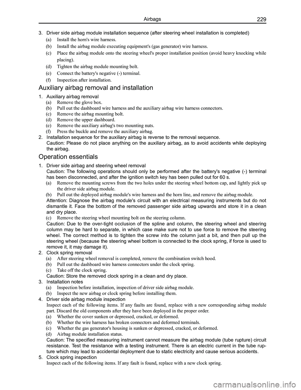
3. Driver side airbag module installation sequence (after steering wheel i\
nstallation is completed)
(a) Install the horn's wire harness.
(b) Install the airbag module executing equipment's (gas generator) wire harness.
(c) Place the airbag module onto the steering wheel's proper installation position (avoid heavy knocking while
placing).
(d) Tighten the airbag module mounting bolt.
(e) Connect the battery's negative (-) terminal.
(f) Inspection after installation.
Auxiliary airbag removal and installation
1. Auxiliary airbag removal
(a) Remove the glove box.
(b) Pull out the dashboard wire harness and the auxiliary airbag wire harness connectors.
(c) Remove the airbag mounting bolt.
(d) Remove the upper dashboard.
(e) Remove the auxiliary airbag's two mounting nuts.
(f) Press the buckle and remove the auxiliary airbag.
2. Installation sequence for the auxiliary airbag is reverse to the removal\
sequence.
Caution: Please do not place anything on the auxiliary airbag, as to avoid accidents while deploying
the airbag.
Operation essentials
1. Driver side airbag and steering wheel removal
Caution: The following operations should only be performed after the battery's negative (-) terminal
has been disconnected, and after the ignition switch key has been pulled\
out for 60 s.
(a) Remove the mounting screws from the two holes under the steering wheel bottom cap, and lightly pick up
the driver side airbag module.
(b) Pull out the deployed airbag module's wire harness and the horn line, and remove the airbag module\
.
Attention: Diagnose the airbag module's circuit with an electrical measuring instruments but do not
dismantle it. Face the bottom of the removed passenger side airbag upwards and store it in a clean
and dry place.
(c) Remove the steering wheel mounting bolt on the steering column.
Caution: Due to the over-tight occlusion of the spline and column, the steering wheel and steering
column may be hard to separate, in which case make sure not to use force to remove the steering
wheel. The correct method is to tighten the screw into the column just a bit, and then pull up the
steering wheel (because the steering wheel bottom is connected to the clock spring, if force is used to
remove it, it may damage it).
2. Clock spring removal
(a) After steering wheel removal is completed, remove the combination switch hood.
(b) Pull out the dashboard wire harness connectors under the clock spring.
(c) Take off the clock spring.
Caution: Store the removed clock spring in a clean and dry place.
3. Installation notes
(a) Inspection before installation, inspection of driver side airbag module.
(b) Inspect the new airbag or clock spring before installing them.
4. Driver side airbag module inspection
Inspect each of the following items. If any faults are found, replace with a new corresponding airbag module
part. Discard the old components after they have been deployed in the pr\
oper order.
(a) Whether the cover sunken or depressed, cracked, or deformed.
(b) Whether the wire harness has broken connectors and deformed terminals.
(c) Whether the gas generator's housing is sunken or depressed, cracked, or deformed.
(d) Airbag module installation status.
Caution: The specified measuring instrument cannot measure the airbag module (tube rupture) circuit
resistance. Test the resistance with a testing instrument. There is an electric current in the tube rup-
ture which may lead to accidental deployment due to static electricity a\
nd cause serious accidents.
5. Clock spring inspection
Inspect each of the following items. If any fault is found, replace with\
a new clock spring.