weight GREAT WALL HOVER 2006 Service Repair Manual
[x] Cancel search | Manufacturer: GREAT WALL, Model Year: 2006, Model line: HOVER, Model: GREAT WALL HOVER 2006Pages: 425, PDF Size: 26.05 MB
Page 11 of 425
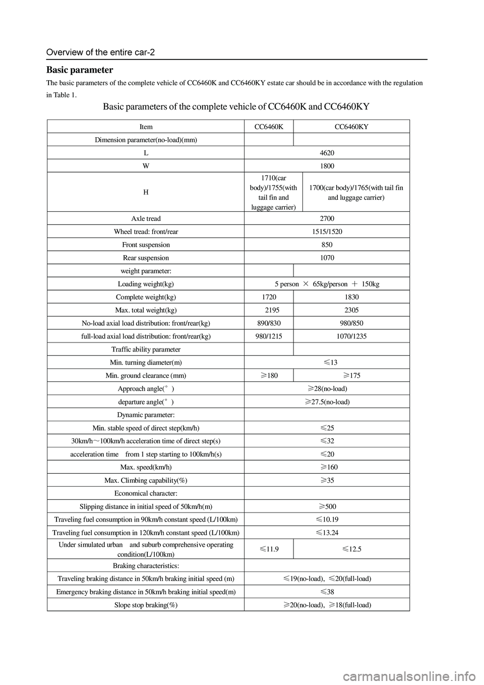
Basic parameter
The basic parameters of the complete vehicle of CC6460K and CC6460KY estate car should be in accordance with the regulation
in Table 1.
Basic parameters of the complete vehicle of CC6460K and CC6460KY
Item CC6460K CC6460KY
Dimension parameter(no-load)(mm)
L 4620
W 1800
H 1710(car
body)/1755(with
tail fin and
luggage carrier) 1700(car body)/1765(with tail fin
and luggage carrier)
Axle tread 2700
Wheel tread: front/rear 1515/1520
Front suspension 850
Rear suspension 1070
weight parameter:
Loading weight(kg) 5 person × 65kg/person + 150kg
Complete weight(kg) 1720 1830
Max. total weight(kg) 2195 2305
No-load axial load distribution: front/rear(kg) 890/830 980/850
full-load axial load distribution: front/rear(kg) 980/1215 1070/1235
Traffic ability parameter
Min. turning diameter(m) ≤13
Min. ground clearance (mm) ≥180 ≥175
Approach angle(°) ≥28(no-load)
departure angle(°) ≥27.5(no-load)
Dynamic parameter:
Min. stable speed of direct step(km/h) ≤25
30km/h~100km/h acceleration time of direct step(s) ≤32
acceleration time from 1 step starting to 100km/h(s) ≤20
Max. speed(km/h) ≥160
Max. Climbing capability(%) ≥35
Economical character:
Slipping distance in initial speed of 50km/h(m) ≥500
Traveling fuel consumption in 90km/h constant speed (L/100km) ≤10.19
Traveling fuel consumption in 120km/h constant speed (L/100km) ≤13.24
Under simulated urban and suburb comprehensive operating
condition(L/100km) ≤11.9 ≤12.5
Braking characteristics:
Traveling braking distance in 50km/h braking initial speed (m) ≤19(no-load), ≤20(full-load)
Emergency braking distance in 50km/h braking initial speed(m) ≤38
Slop e stop braking(%) ≥20(no-load), ≥18(full-load)
Page 12 of 425
Overview of the entire car-3
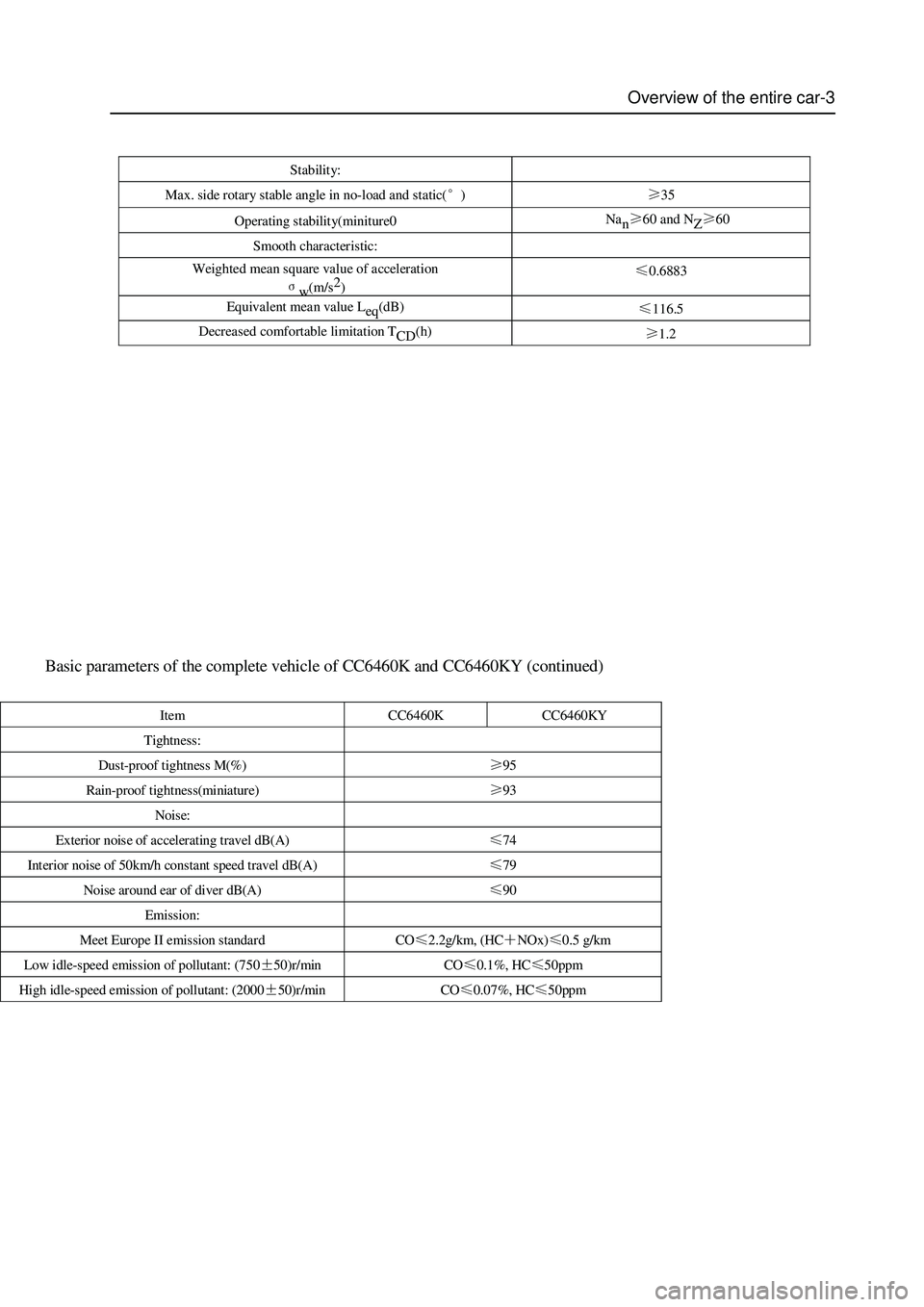
Stability:
Max. side rotary stable angle in no-load and static(°) ≥35
Operating stabilit y(miniture0 Na
n≥60 and N
Z≥60
Smooth characteristic:
Weighted mean square value of acceleration
σ
w(m/s2
) ≤0.6883
Equivalent mean value L
eq(dB)
≤116.5
Decreased comfortable limitation T
CD(h)
≥1.2
Basic parameters of the complete vehicle of CC6460K and CC6460KY (continued)
Item CC6460K CC6460KY
Tightness:
Dust-proof tightness M(%) ≥95
Rain-proof tightness(miniature) ≥93
Noise:
Exterior noise of accelerating travel dB(A) ≤74
Interior noise of 50km/h constant speed travel dB(A) ≤79
Noise around ear of diver dB(A) ≤90
Emission:
Meet Europe II emission standard CO≤2.2g/km, (HC+NOx)≤0.5 g/km
Low idle-speed emission of pollutant: (750±50)r/min CO≤0.1%, HC≤50ppm
High idle-speed emission of pollutant: (2000±50)r/min CO≤0.07%, HC≤50ppm
Page 14 of 425
Overview of the entire car-5
The friction, disc, single-diaphragm spring clutch, hydraulic control mechanism. The external diameter of friction disc D=225mm,
internal diameter d=150mm, material is F810.
Adjustment of clutch pedal:
1. Measure the height of clutch pedal (from pedal pad surface to floor) and free stroke of clutch pedal (fork bar pin clearance).
Standard height of clutch pedal: flush with the brake pedal, free stroke of clutch pedal is 5-15mm;
2. Readjust the free stroke of pedal after adjust the height of pedal; rotate the push bar to the standard value, then fix the bolt
and nut;
3. If the free stroke of clutch pedal is not within standard value, it should rotate the adjusting bolt to standard value, then fix
the bolt and nut. Do not move the push bar to main cylinder when adjust the free stroke of pedal;
4. If the free stroke of clutch pedal and clearance between the clutch pedal and floor when the clutch is disengaged de not
consist with the standard, this may by caused by the air in hydraulic system and failure of main cylinder or clutch. It can
discharge the air of system or dissemble and inspect the main cylinder or clutch.
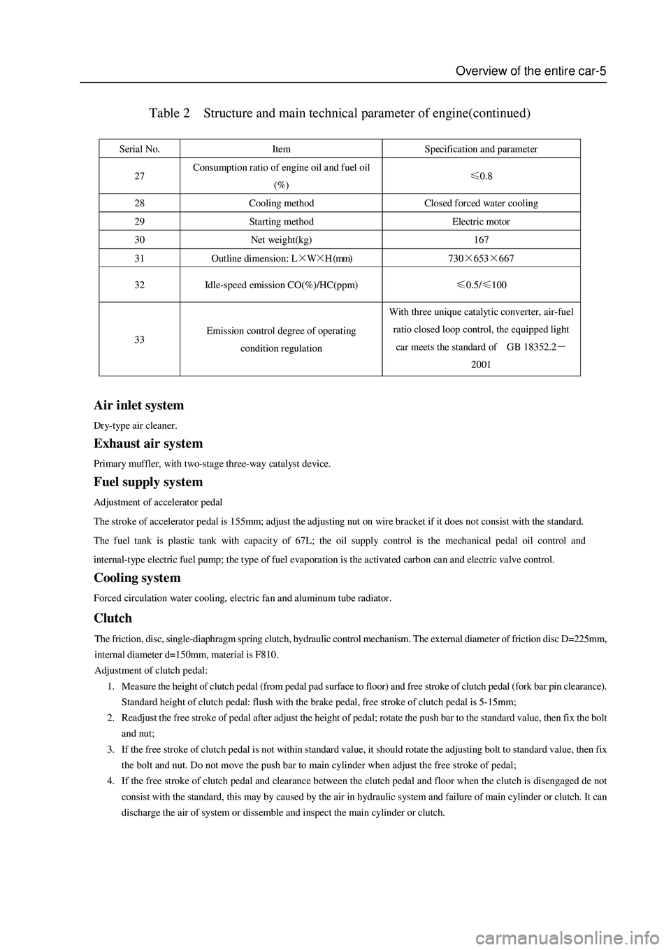
Table 2 Structure and main technical parameter of engine(continued)
Serial No. Item Specification and parameter
27 Consumption ratio of engine oil and fuel oil
(%) ≤0.8
28 Cooling method Closed forced water cooling
29 Starting method Electric motor
30 Net weight(kg) 167
31 Outline dimension: L×W×H (mm) 730×653×667
32 Idle-speed emission CO(%)/HC(ppm) ≤0.5/≤100
33 Emission control degree of operating
condition regulation With three unique catalytic converter, air-fuel
ratio closed loop control, the equipped light
car meets the standard of GB 18352.2-
2001
Air inlet system
Dry-type air cleaner.
Exhaust air system
Primary muffler, with two-stage three-way catalyst device.
Fuel supply system
Adjustment of accelerator pedal
The stroke of accelerator pedal is 155mm; adjust the adjusting nut on wire bracket if it does not consist with the standard.
The fuel tank is plastic tank with capacity of 67L; the oil supply control is the mechanical pedal oil control and
internal-type electric fuel pump; the type of fuel evaporation is the activated carbon can and electric valve control.
Cooling system
Forced circulation water cooling, electric fan and aluminum tube radiator.
Clutch
Page 15 of 425
Front shaft/axle
CC6460K wagon has the two-cross arm, independent suspension, breakaway front axle.
CC6460KY wagon has the two-cross arm, independent suspension, breakaway steering drive axle , hyperbolic gear single-stage main
reducer, plain bevel gear differential mechanism, universal drive semiaxle, Birfield ball-joint, main reduction ratio i
0=4.55, Max. input
torque is 900N
m.
Rear axle
Non-breakaway drive axle, integral stamping-welded axle housing, hyperbolic gear single-stage main reducer, plain bevel gear differential
mechanism, semi-floating semiaxle, main reduction ratio i
0=4.55, Max. input torque is 900Nm.
Wheel and tyre
The type, specification and main parameter of wheel and tyre see Table 4.
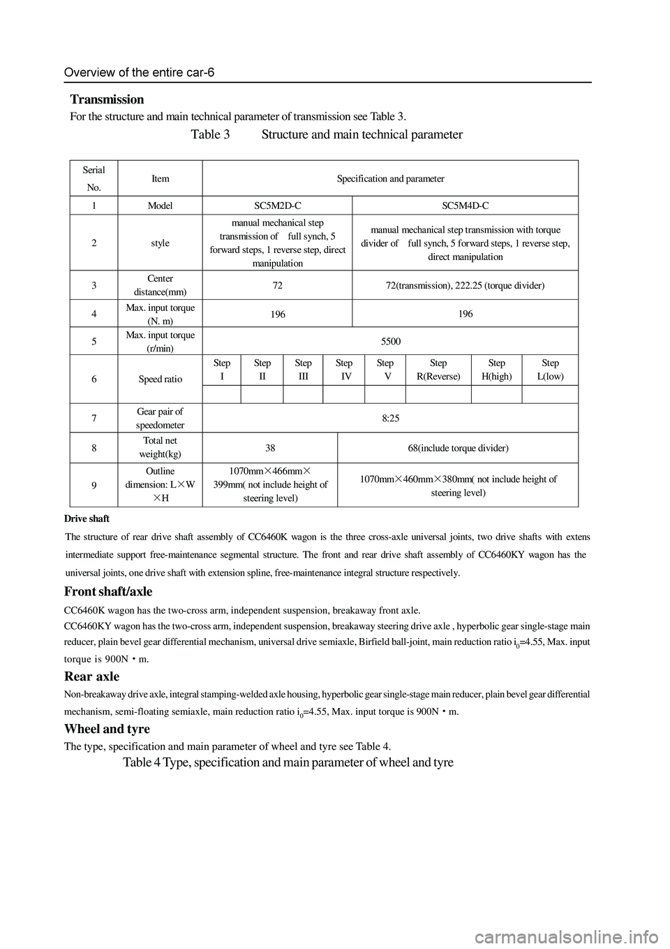
Table 4 Type, specification and main parameter of wheel and tyre
Transmission
For the structure and main technical parameter of transmission see Table 3.
Table 3 Structure and main technical parameter
Serial
No. Item Specification and parameter
1 Model SC5M2D-C SC5M4D-C
2 style manual mechanical step
transmission of full synch, 5
forward steps, 1 revers e step, direct
manipulation manual mechanical step transmission with torque
divider of full synch, 5 forward steps, 1 reverse step,
direct manipulation
3 Cent er
distance(mm) 72 72(transmission), 222.25 (torque divider)
4 Max. input torque
(N. m) 196 196
5 Max. input torque
(r/min) 5500
Step
I Step
II Step
III St ep
IV Step
V Step
R(Reverse) Step
H(high) St ep
L(low)
6 Speed ratio
7 Gear pair of
speedometer 8:25
8 To t a l n et
weight(kg) 38 68(include torque divider)
9 Outline
dimension: L×W
×H 1070mm×466mm×
399mm( not include height of
steering level) 1070mm×460mm×380mm( not include height of
steering level)
Drive shaft
The structure of rear drive shaft assembly of CC6460K wagon is the three cross-axle universal joints, two drive shafts with exten
s
intermediat e support free-maint enance segmental structure. The front and rear dr ive shaft assembly of CC6 460KY wa gon has the
universal joints, one drive shaft with extension spline, free-maintenance integral structure respectively.
Page 80 of 425
Automatic transmission-4
10. The gross weight of the transmission is 76kg; mostly weight is on the front of the transmission (side of torque converter). This
should be considered when design the handling/assembly tools.
11. The crankshaft speed/position sensor is installed on the top of transmission torque converter housing which must be installed
after the transmission is installed on the engine. The sensor will be damaged if it is installed before the installation of
transmission.
12. The transmission use the breathing tube connected to rear end of transmission. The tube must not be restricted or blocked
otherwise the air pressure in transmission will be increased. It is unallowable that the water/dirty/dust enters into the
breathing tube; otherwise the transmission will be damaged.
Removal of transmission
If the transmission needs removing for any reasons, following is the preventive measure to help the remove.
1. Must not only support the oil pan in middle of transmission for it will be deformed and leaked. The oil pan will not be deformed
when supports its external edge.
2. It must not allow the transmission to connect to the engine when the rear end is without connection, otherwise the exhaust
system of vehicle will be damaged.
3. Remove all torque converter bolts and push back the torque converter before remove the bolt connected the torque converter
housing to engine. Once all bolts connected the torque converter housing to engine are removed, use the torque converter the
push the transmission from the location pin, then ensure the torque converter is on the transmission and the transmission is
separated form location pin.
4. Install the dustproof cover on the cooler connector rapidly after open the oil cooler pipe; otherwise the oil leakage from the
torque converter will be 2L. The odometer dustproof cover can prevent the dirty from entering into the transmission and avoids
the leakage of oil form transmission.
5. The engine speed sensor is installed on the top of transmission and should be removed before the transmission is removed form
the engine, for the sensor will be damaged during the removal process of the transmission.
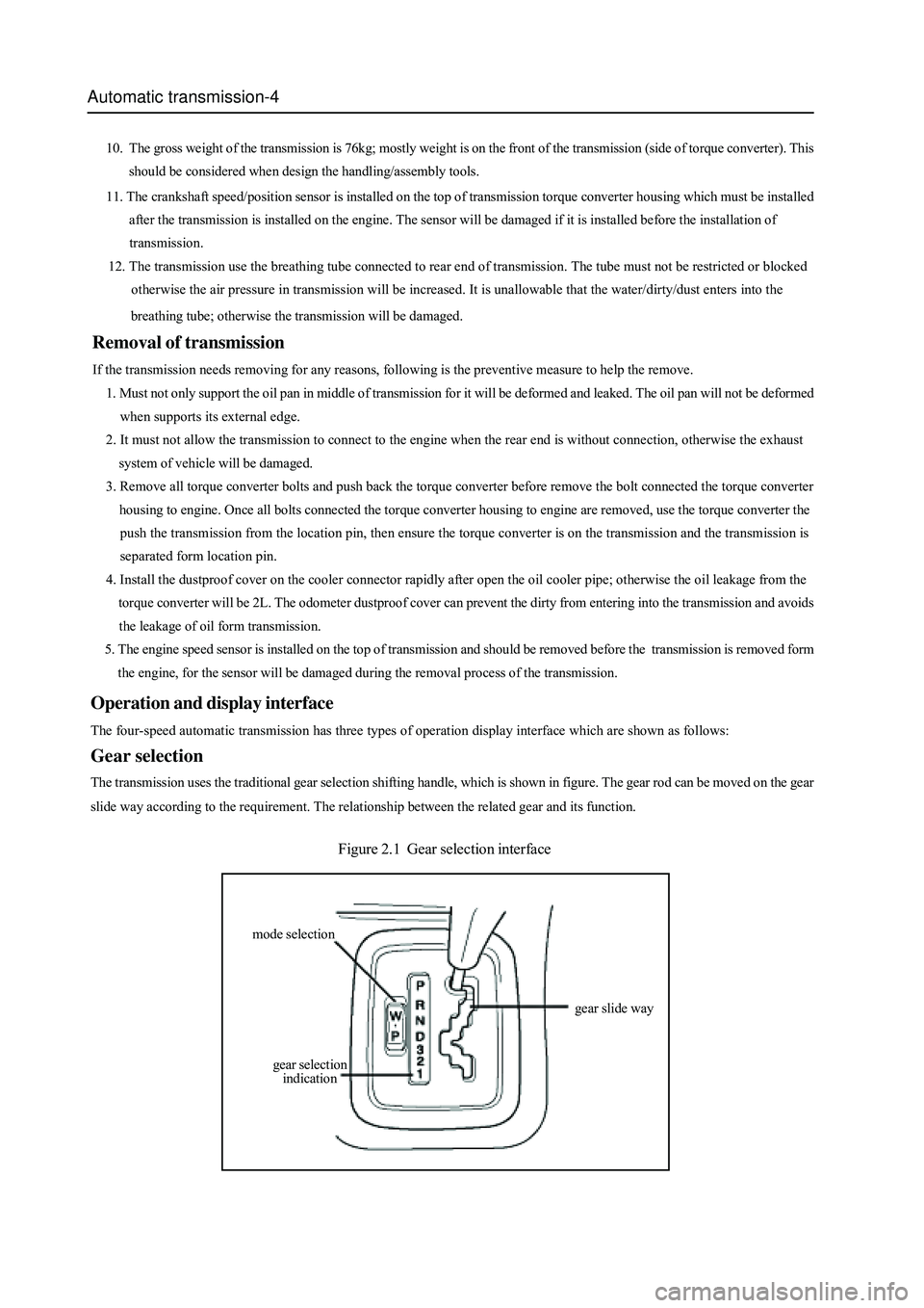
Figure 2.1 Gear selection interface
mode selection
gear selection
indicationgear slide way
Operation and display interface
The four-speed automatic transmission has three types of operation display interface which are shown as follows:
Gear selection
The transmission uses the traditional gear selection shifting handle, which is shown in figure. The gear rod can be moved on the gear
slide way according to the requirement. The relationship between the related gear and its function.
Page 146 of 425
o. Maintain the horizontal position of cylinder , install the sleeve and clutch disk assembly on the cylinder; ensure the top of
washer and external hole of cylinder are in order until the sleeve can contact the C2 wave plate.
Caution:
For the C2 wave spring is compressed and the clutch disk can endure the weight of 19.6N. The dimension form the lower
side of C2 pressure disc to the gear selection steel plate is 1.4
1.8mm. if the clutch need to start the accuracy from the
top of pressure plate, then the accurate value should be the actual size of pressure plate plus 1.4
1.8mm.
p. Use the special tools to check the C4 clutch assembly. Refer to Figure 8.25.
Caution:
It should take out the clutch clearance assembly before immerse the assembly into the automatic transmission fluid
(ATF).
q. Use the gear selection plate to reach the correct specification. If need to install the new friction disk, it should remove the
clutch assembly and immerse the friction disk in the automatic transmission fluid for 5 minutes at least before the installation.
Reinstall the sleeve and clutch assembly and place it in the cylinder. Ensure the wave washer is arranged consisting with the
cylinder hole.
Install the clutch C2 disk in the cylinder according to the following procedure:
friction disk
steel disc
friction disk
steel disc
The steel disc transmission use the G32 model engine; the 5th friction disk should replace the steel disc (reference table 9.3).
steel disc (optional)
friction disk
steel disc (optional)
friction disk
Caution:
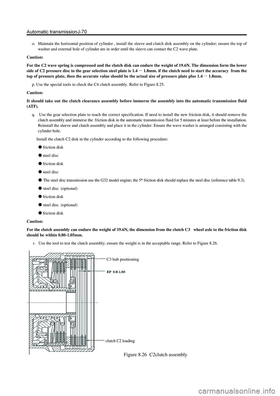
For the clutch assembly can endure the weight of 19.6N, the dimension from the clutch C3 wheel axle to the friction disk
should be within 0.80-1.05mm.
r. Use the tool to test the clutch assembly; ensure the weight is in the acceptable range. Refer to Figure 8.26.
C3 hub positioning
clutch C2 loading
Figure 8.26 C2clutch assembly
Page 148 of 425
b. Check the damage of external diameter and central support diameter of C3 cylinder sleeve. Coat the sealing ring with the
automatic transmission fluid and install it on the C3 cylinder groove.
c. Check the condition of reverse central gear spline, notch and thrust surface; coat the O-ring with transmission liquid and install
it in the reverse sun gear groove. Use the Vaseline to lubricate the C3 washer and install it in the reverse sun gear.
d. Install the reverse central gear in the C3 cylinder; ensure the O-ring is compressed properly but not excess.
Caution:
The O-ring notch can not be bent.
e. Coat the C3 piston O-ring with the transmission liquid and install the small O-ring on the C3 piston inner ring; install the large
O-ring on the C3 piston external ring.
f. Check the piston drainage hole for cleanness and block material.
Caution:
Must not remove the O-ring without permission.
g. Install the C3 piston on the cylinder until the external diameter of piston enters into the inner diameter of cylinder.
h. Install the spring and spring retainer on the piston. Use the tools to press down the spring to install the ring spring better.
Ensure the ring spring is installed in the groove fixedly, then remove the tools.
i. Install the C3 wave plate on the C3 piston surface; ensure the a hole on wave disc of C3 piston surface is not in line with the
piston hole.
j. Install the clutch disk and other disc in the following sequence:
steel disc
friction disk
steel disc (optional)
friction disk
steel disc (optional)
friction disk
k. Adjust and install the pressure disc; make its counterbore is opposite with the clutch disk.
l. Install the ring spring.
Caution:
For the clutch assembly can endure the weight of 19.6N. so the clearance between the screw and top of preset disc should
be 1.20-1.45mm.
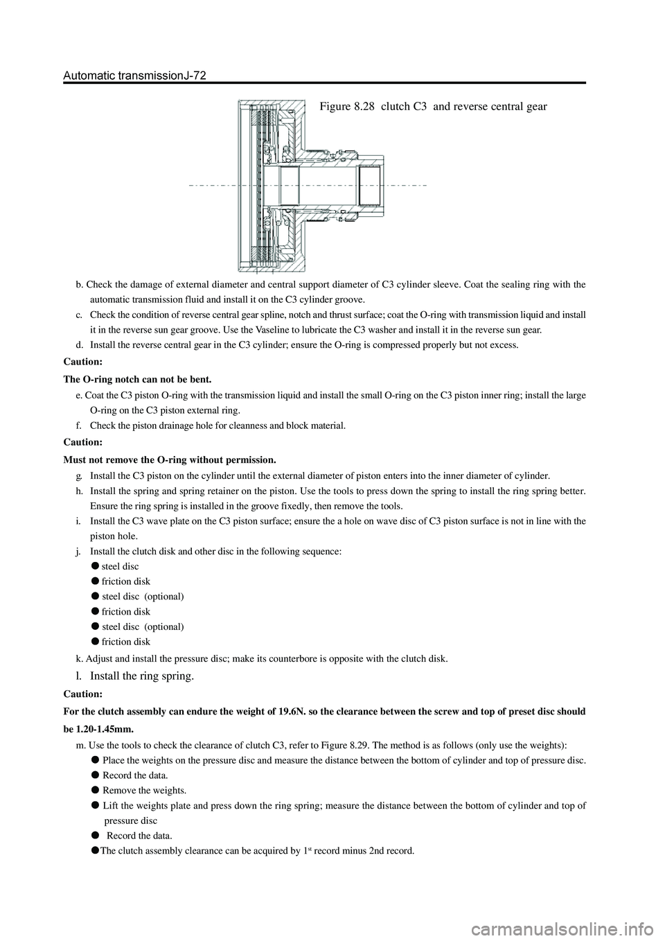
m. Use the tools to check the clearance of clutch C3, refer to Figure 8.29. The method is as follows (only use the weights):
Place the weights on the pressure disc and measure the distance between the bottom of cylinder and top of pressure disc.
Record the data.
Remove the weights.
Lift the weights plate and press down the ring spring; measure the distance between the bottom of cylinder and top of
pressure disc
Record the data.
The clutch assembly clearance can be acquired by 1st record minus 2nd record.
Figure 8.28 clutch C3 and reverse central gear
Page 150 of 425
12. Clutch C1 overspeed shaft and input shaft assembly
Caution:
a. Ensure the correct installation of snap ring.
b. Check the piston for crack.
c. Must not mix the clutch piston out and back spring.
d. If the connector of clutch C1/ C2 is disconnected form the clutch C3, ensure the NO.6 bearing can not slide down
from the bearing retainer.
The installation procedure of clutch C1 overspeed shaft and input shaft assembly is as follows:
a. Check the overspeed shaft groove for damage.
b. Coat the big and small sealing ring with the Vaseline and install it on the overspeed shaft. It can use few Vaseline to fix the
sealing ring on its correct position.
c. Install the clutch disk and other disc on the cylinder according to the following sequence:
steel plate
abrasion plate
steel plate
abrasion plate
steel plate
steel plate
steel plate (optional)
friction disk
steel plate (optional)
friction disk
Caution:
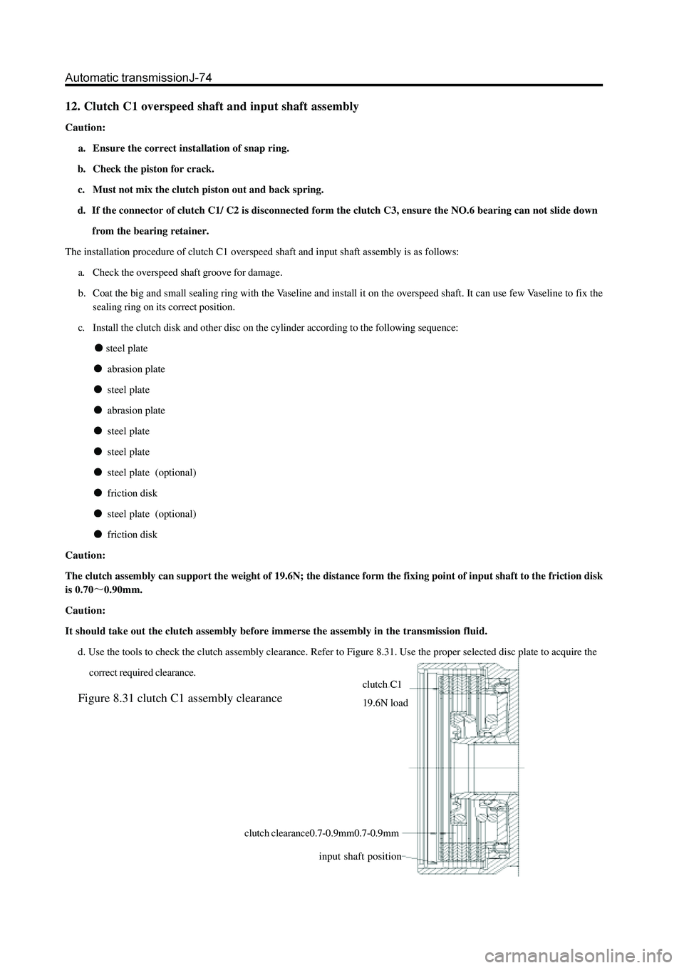
The clutch assembly can support the weight of 19.6N; the distance form the fixing point of input shaft to the friction disk
is 0.70
0.90mm.
Caution:
It should take out the clutch assembly before immerse the assembly in the transmission fluid.
d. Use the tools to check the clutch assembly clearance. Refer to Figure 8.31. Use the proper selected disc plate to acquire the
correct required clearance.
Figure 8.31 clutch C1 assembly clearance
clutch C1
19.6N load
input shaft position
clutch clearance0.7-0.9mm0.7-0.9mm
Page 174 of 425
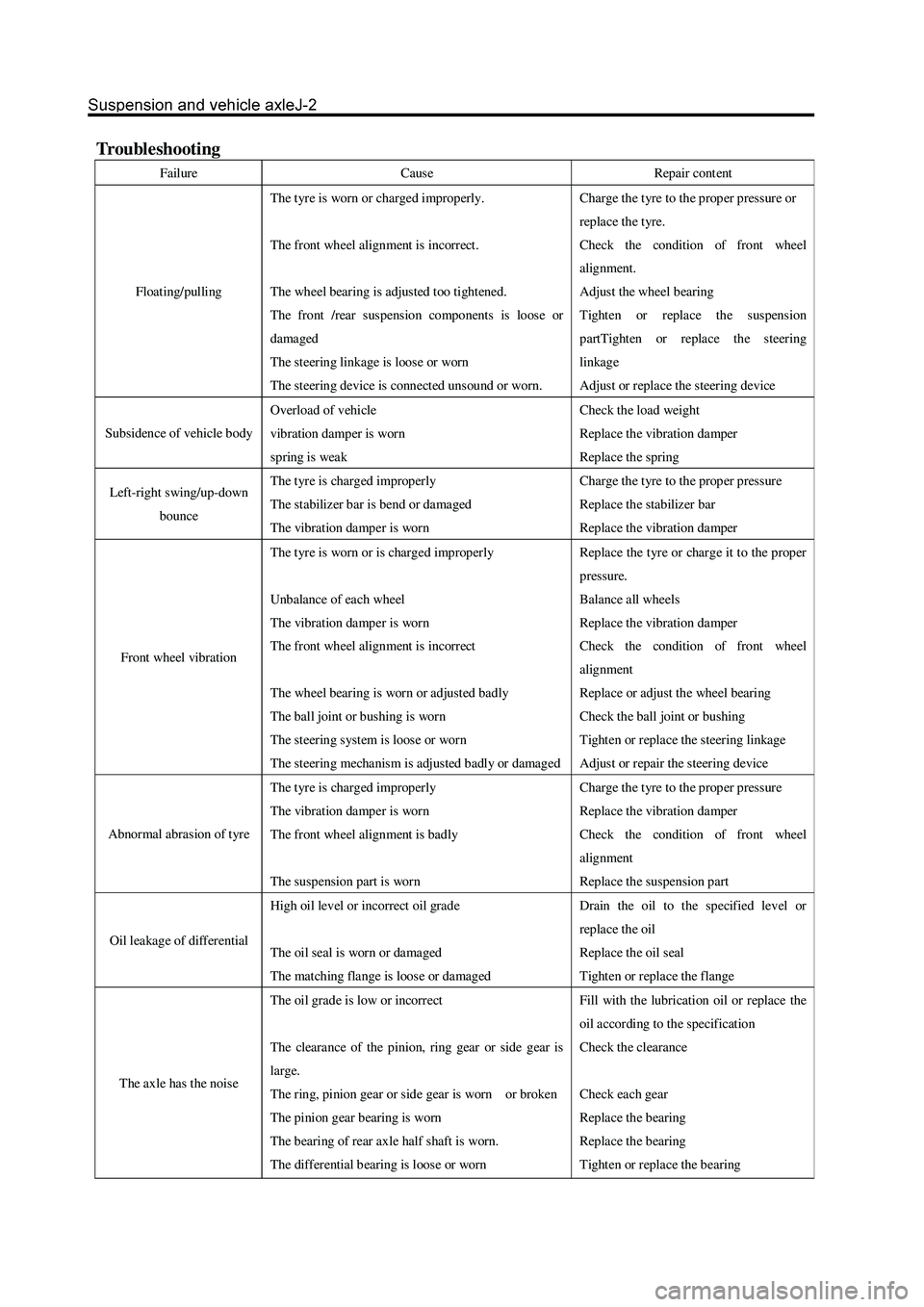
Troubleshooting
Failure Cause Repair cont ent
Floating/pulling The t yre is worn or charged improperly.
The front wheel alignment is incorrect.
The wheel bearing is adjusted too tightened.
The front /rear suspension components is loose or
damaged
The steering linkage is loose or worn
The steering device is connect ed unsound or worn. Charge the t yre to the prop er pressur e or
repla ce the t yre.
Check the condition of front wheel
alignment.
Adjust the wheel bearing
Tighten or replace the suspension
partTighten or replace the steering
linkage
Adjust or replace the steering device
Subsidence of vehicle body Overload of vehicle
vibration damper is worn
spring is weak Check the load weight
Replace the vibration damper
Replace the spring
Left-right swing/up-down
bounce The t yre is charged improperly
The stabilizer bar is bend or damaged
The vibration damper is worn Charge the t yre to the prop er pressur e
Replace the stabilizer bar
Replace the vibration damper
Front wheel vibration The t yre is worn or is charged improperly
Unbalance of each wheel
The vibration damper is worn
The front wheel alignment is incorrect
The wheel bearing is worn or adjusted badly
The ball joint or bushing is worn
The steering system is loose or worn
The steering mechanism is adjusted badly or damaged Repla ce the t yr e or char ge it to the prop er
pressure.
Balance all wheels
Replace the vibration damper
Check the condition of front wheel
alignment
Replace or adjust the wheel bearing
Check the ball joint or bushing
Tighten or replace the steering linkage
Adjust or repair the steering device
Abnormal abrasion of tyre The t yre is charged improperly
The vibration damper is worn
The front wheel alignment is badly
The suspension part is worn Charge the t yre to the prop er pressur e
Replace the vibration damper
Check the condition of front wheel
alignment
Replace the suspension part
Oil leakage of differential High oil level or incorrect oil grade
The oil seal is worn or damaged
The matching flange is loose or damaged Drain the oil to the specified level or
repla ce the oil
Replace the oil seal
Tighten or replace the flange
The axle has the nois e The oil grade is low or incorrect
The clearance of the pinion, ring gear or side gear is
large.
The ring, pinion gear or side gear is worn or broken
The pinion gear bearing is worn
The b earing of rear axle half shaft is worn.
The differential b earing is loos e or worn Fill with the lubrication oil or replace the
oil according to the specification
Check the clearance
Check each gear
Replace the bearing
Replace the bearing
Tighten or replace the bearing
Page 241 of 425
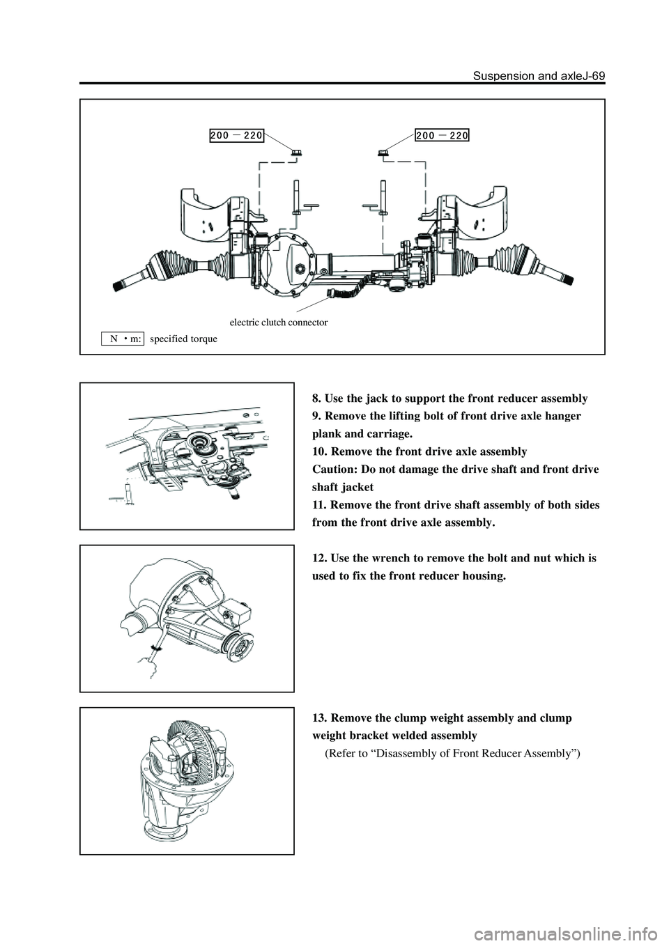
8. Use the jack to support the front reducer assembly
9. Remove the lifting bolt of front drive axle hanger
plank and carriage.
10. Remove the front drive axle assembly
Caution: Do not damage the drive shaft and front drive
shaft jacket
11. Remove the front drive shaft assembly of both sides
from the front drive axle assembly.
12. Use the wrench to remove the bolt and nut which is
used to fix the front reducer housing.
13. Remove the clump weight assembly and clump
weight bracket welded assembly
(Refer to “Disassembly of Front Reducer Assembly”)
electric clutch connector
N
m: specified torque