Timing check HONDA CIVIC 1996 6.G User Guide
[x] Cancel search | Manufacturer: HONDA, Model Year: 1996, Model line: CIVIC, Model: HONDA CIVIC 1996 6.GPages: 2189, PDF Size: 69.39 MB
Page 196 of 2189
Cylinder Head
Installation (cont'dl
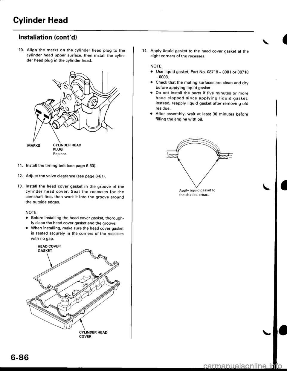
10. Align the marks on the cylinder head plug to thecylinder head upper surface, then install the cylin,
der head plug in the cylinder head.
PLUGReplace.
Install the timing belt (see page 6-63).
Adjust the valve clearance (see page 6-61).
Install the head cover gasket in the groove of the
cylinder head cover. Seat the recesses for the
camshaft first, then work it into the groove around
the outside edges,
NOTE:
. Before installing the head cover gasket, thorough-ly clean the head cover gasket and the groove.
. When installing, make sure the head cover gasket
is seated securely in the corners of the recesses
wrrn no gap.
11.
13.
1'
CYLINDEB HEAD
HEAD COVEB
6-86
(\
14. Apply liquid gasket to the head cover gasket at theeight corners of the recesses.
NOTE:
. Use liquid gasket, Part No. 08718 - 0001 or 08718- 0003.
. Check that the mating surfaces are clean and drybefore applying liquid gasket
. Do not install the parts if five minutes or morehave elapsed since applying tiquid gasket.
Instead, reapply liquid gasket after removing oldrestdue.
. After assembly. wait at least 30 minutes before
filling the engine with oil.
Page 226 of 2189
Oil Seals
lnstallation
NOTE:
. Engine removal is not required.
. The crankshaft oil seal housing should be dry.
Apply a light coat of grease to the crankshaft and to
the lips of the seals.
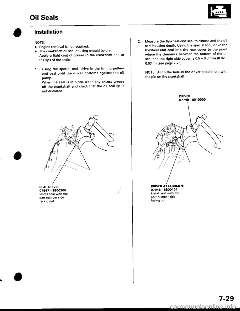
1. Using the special tool, drive in the timing pulley-
end seal until the driver bottoms against the oil
pump.
When the seal is in place, clean any excess grease
off the crankshaft and check that the oil seal lip is
not distorted.
07947 -S800200
lnstall seal with thepart number sadefacing out.
I
2. Measure the flvwheel-end seal thickness and the oil
seal housing depth. Using the special tool. drive the
flywheel-end seal into the rear cover to the point
where the clearance between the bottom of the oil
seal and the right side cover is 0.5 - 0.8 mm (0.02 -
0.03 in) (see page 7-23).
NOTE: Align the hole in the driver attachment with
the Din on the crankshaft.
DRIVER ATTACHMENT0794a-s800101lnslall seal with thepart number sidefacing out.
DRIVER07749-0010000
7 -29
Page 239 of 2189
4.
Removal/lnspection/lnstallation
2.
3.
1.
5.
6.
1.
8.
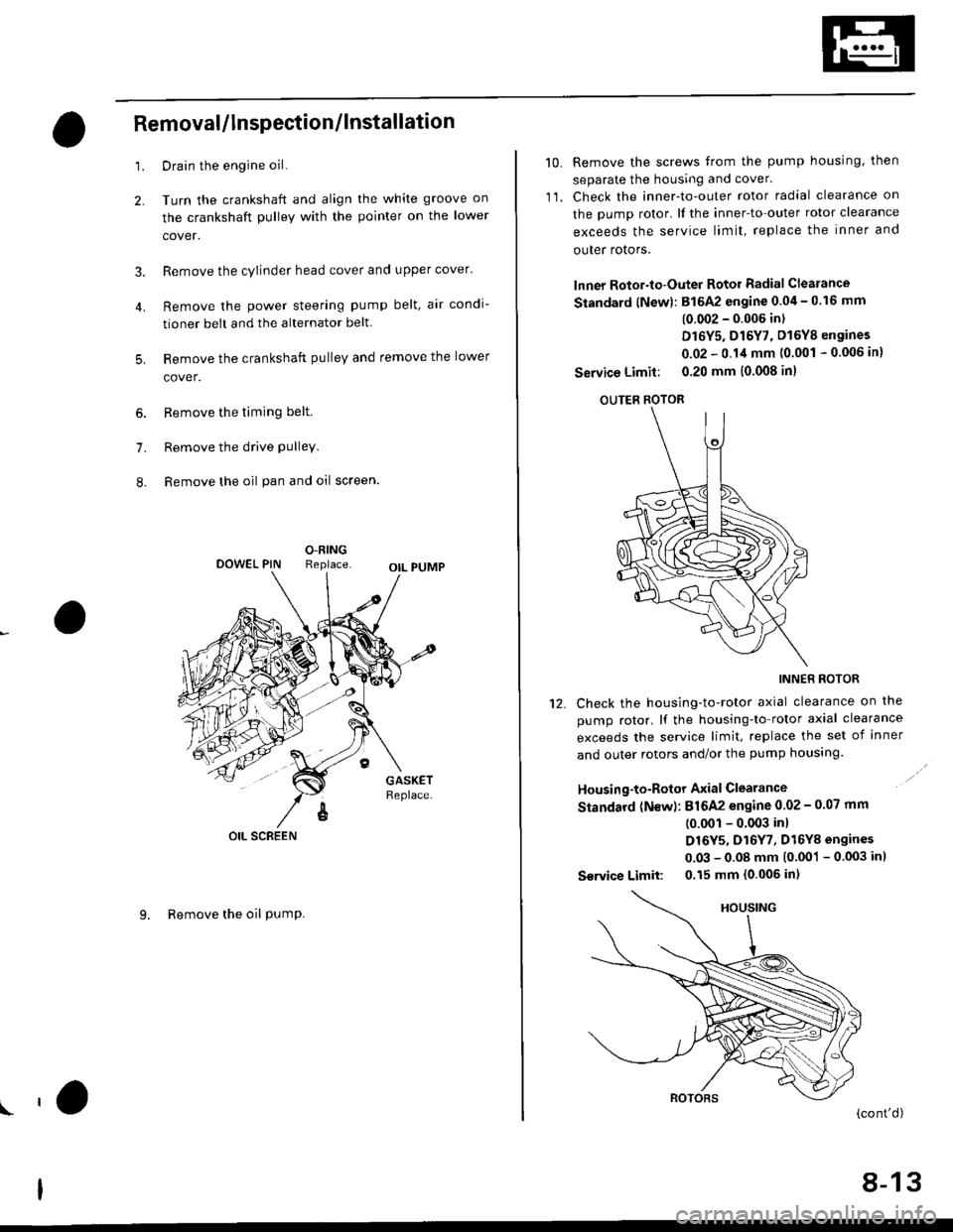
Drain the engine oil.
Turn the crankshaft and align the white groove on
the crankshaft pulley with the pointer on the lower
cover.
Remove the cylinder head cover and upper cover'
Remove the power steering pump belt, air condi-
tioner beit and the alternator belt
Remove the crankshaft pulley and remove the lower
cover.
Remove the timing belt.
Remove the drive pulley.
Remove the oil pan and oil screen.
O.RINGReplaceOOWEL PIN
OIL SCREEN
9. Remove the oil PumP.
!'a
10.Remove the screws from the pump housing, then
separate the housing and cover'
Check the inner-to-outer rotor radial clearance on
the pump rotor. lf the inner-to outer rotor clearance
exceeds the service limit, replace the inner and
outer rotors.
lnner Rotor-to-Outer Rotor Radial Clearance
Standard {New}: 815A2 engine 0.04 - 0.16 mm
(0 002 - 0'006 in)
D16Y5, D16Y7, D16Y8 engines
0.02 - 0.14 mm 10.001 - 0.006 in)
Service Limit: 0.20 mm (0 008 inl
OUTER ROTOR
INNER ROTOR
Check the housing-to-rotor axial clearance on the
pump rotor. lf the housing-to rotor axial clearance
exceeds the service limit, replace the set of inner
and outer rotors and/or the pump housing
Housing-to-Rotor Axial Clearance
Standard (N€w): 816A2 engine 0.02 - 0.07 mm
(0.001 - 0.003 inl
D16Y5, D16Y7, D16Y8 engines
0.03 - 0.08 mm (0.001 - 0.003 inl
S€rvice Limit: 0.15 mm 10.006 in)
11.
't2.
(cont'd)
8-13
Page 269 of 2189
Water Pump
Inspection
't.
2.
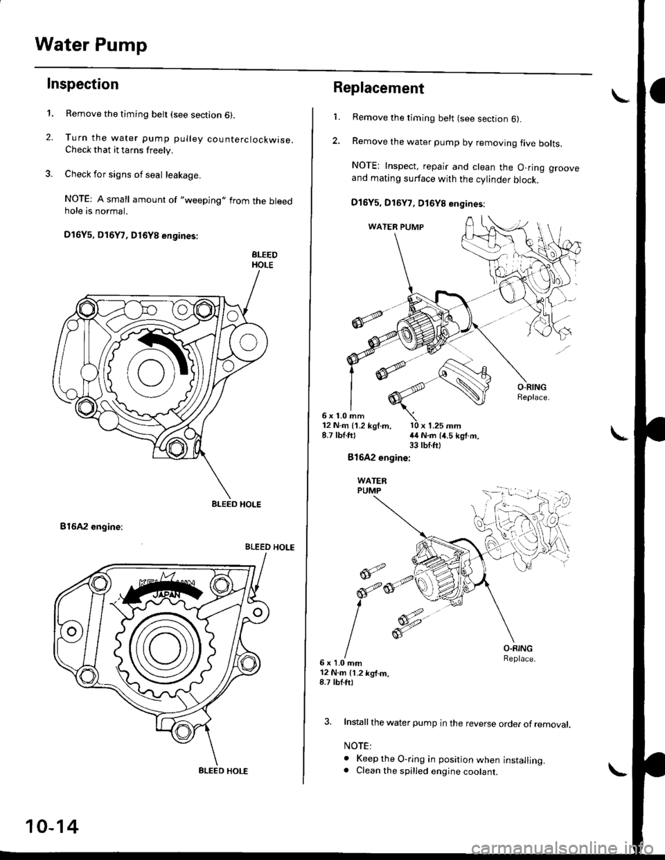
Remove the timing belt (see section 6).
Turn the water pump pulley counterclockwise.Check that it tarns freely.
Check for signs of seal leakage.
NOTE: A small amount of "weeping,,from the bleedhole is normal.
Dl6Y5, Dl6Y7, D16Y8 engines:
BLEEDHOLE
B16A2 engine:
BLEED HOLE
BLEED HOLE
BLEED HOLE
10-14
Replacement
6x1.0mm
1.Remove the timing belt (see section 6).
Remove the water pump by removing five bolts.
NOTE: Inspect, repair and clean the O-ring grooveand mating surface with the cylinder block.
D16Y5, D16Y7, D16Y8 engines:
12 N.m {1.2 kgf.m, l0 x 1.25 mm8.7 lbt.ft) {4 N.m 14.5 kg{.m.33 tbt.ft)
Bl642 engine:
WATERPUMP
@;2
6x1.0mm12 N.m 11.2 kg{.m,8.7 tbf.ft)
O.RINGReplace.
3. Install the water pump in the reverse order of removal.
NOTE:
o Keep the O-ring in position when installing.. Clean the spilled engine coolant.
d
orp,
I
Page 441 of 2189
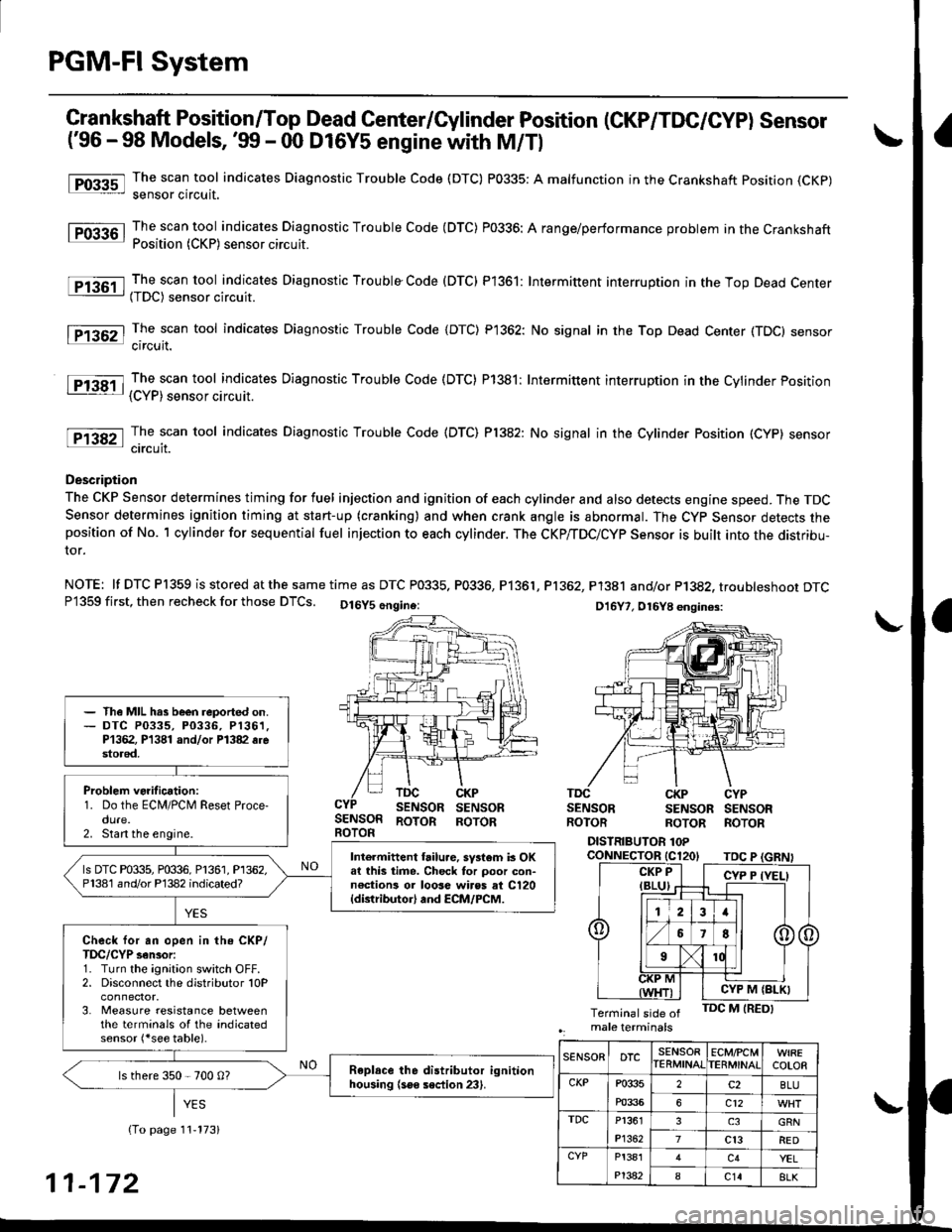
PGM-FI System
tFos3sl
tFffi6l
tPr361 I
fPfi62l
fFr38il
tF13s2-l
Crankshaft Position/Top Dead Genter/Gylinder Position (CKP/TDC/CYP) Sensor
('96 - 98 Models, '!n - 00 D16Y5 engine with M/Tl
The scan tool indicates Diagnostic Trouble Code (DTC) P0335: A malfunction in the Crankshaft position (CKp)
sensor circuit.
The scan tool indicates Diagnostic Trouble Code (DTC) P0336: A range/performance problem in the CrankshaftPosition (CKP) sensor circuit.
The scan tool indicates Diagnostic Trouble Code (DTC) P1361: Intermittent interruotion in the Too Dead Center(TDC) sensor circuit.
The scan tool indicates Diagnostic Trouble Code {DTC) P1362: No signal in the Top Dead Center (TDC} sensorcircuit.
The scan tool indicates Diagnostic Trouble Code (DTC) P1381: Intermittent interruption in the Cvlinder Position{CYP) sensor circuit.
The scan tool indicates Diagnostic Trouble Code {DTC) Pl382: No signal in the Cylinder Position (CYP} sensorcircuit.
Description
The CKP Sensor determines timing for fuel injection and ignition of each cylinder and also detects engine speed. The TDCSensor determines ignition timing at start-up (cranking) and when crank angle is abnormal. The Cyp Sensor detects theposition of No. 1 cylinder for sequential fuel injection to each cylinder. The CKP/TDC/CYP Sensor is built into the distribu-ror.
NOTE: lf DTC P1359 is stored atthesametime as DTC P0335. P0336, P1361, Pl362, P1381 and/or P1382, troubteshoor DTCP1359 first, then recheck for those DTCS. Ot6y5 6ngine: Dt6y7, ot6y8 enqin6s:
SENSORBOTOR
TDCSENSORCKPSENSORSENSORROTORSENSORROTORSENSORROTORROTORROTOR
DISTRIBUTOR 1OPcoNNECTOR tC120tTDC P
- The MIL hrs been reported on.- DTC P0335, P0336, P1361,P1362, P1381 and/or Pl382 6restored,
Problem verification:1. Do the ECM/PCM Reset Proce-dure.2. Stan the engine.
Intermittent hilu.e, system b OKat this time. Check tor poor con-n€ctions or 10036 wiros at C120{distributor} and ECM/PCM.
ls DTC P0335, P0336, P1361, P1362,P1381 and/or P'l382 indicated?
Check for an open in the CKP/TDC/CYP sensor:1. Turn the ignition switch OFF.2. Disconnect the distributor 10P
3. Measure resistance betweenthe terminals of the indicatedsensor (*see table).
Replace the distributor ignitionhousing (soe section 23).ls there 350 - 700 0?
CYP M {BLK}
SENSORDTCSENSORIERMINATECMfCMTERMINATCOLOR
CKPP033s
m336
2c2BLU
6c12
TDCP1361
P1362
3GRN
7cl3RED
CYPP!381
P't382
c4YEL
8c148LK11-172
Page 443 of 2189
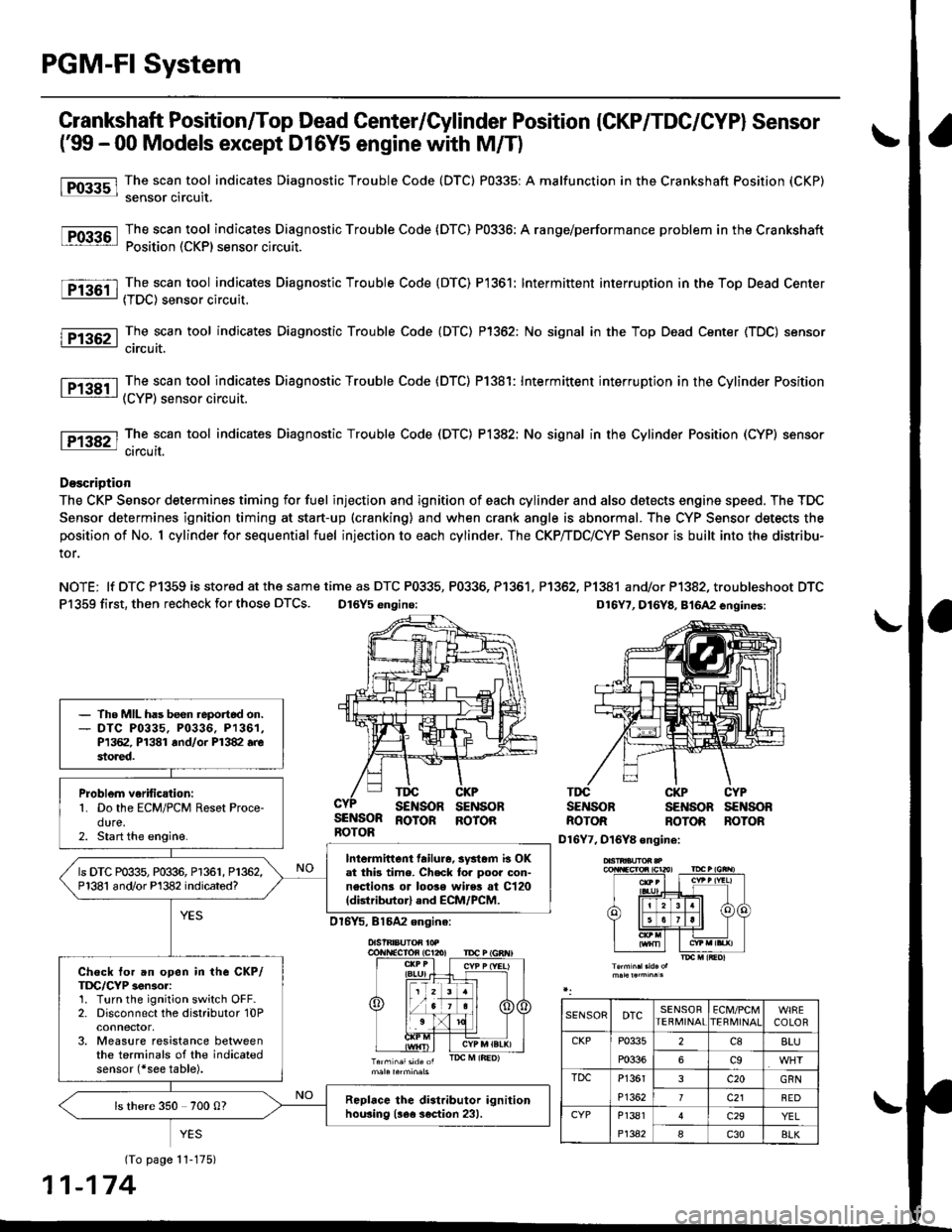
PGM-FI System
l-Fos3sl
tFos36l
tF1361 l
Fr362-1
tF13sil
Crankshaft Position/Top Dead Center/Cylinder Position (CKP/TDC/CYPI Sensor
f99 - 00 Models except D16Y5 engine with M/T)
The scan tool indicates Diagnostic Trouble Code (DTC) P0335: A malfunction in the Crankshaft Position (CKP)
sensor circuit.
The scan tool indicates Diagnostic Trouble Code (DTC) P0336: A range/performance problem in the Crankshaft
Position (CKP) sensor circuit.
The scan tool indicates Diagnostic Trouble Code (DTC) P1361: Intermittent interruption in the Top Dead Center
{TDC) sensor circuit.
The scan tool indicates Diagnostic Trouble Code {DTC) P1362: No signal in the Top Dead Center (TDC) sensor
circuit.
The scan tool indicates Diagnostic Trouble Code (DTC) P1381: Intermittent interruption in the Cylinder Position(CYP) sensor circuit.
lTiaSt The scan tool indicates Diagnostic Trouble Code (DTC) P1382; No signal in the Cylinder Position (CYP) sensor: circuil.
DoscriDtion
The CKP Sensor determines timing for fuel injection and ignition of each cylinder and also detects engine speed. The TDC
Sensor determines ignition timing at start-up (cranking) and when crank angle is abnormal. The CYP Sensor detects the
position of No. 1 cylinder for sequential fuel injection to each cylinder. The CKP/TDC/CYP Sensor is built into the distribu-
tor.
NOTE; lf DTC P1359 is stored at the same time as DTC P0335, P0336, P1361. P1362, P1381 and/or P1382, troubleshoot DTC
P1359 first, then recheck for those DTCS. D16Y5 engino:
SENSORROTOR
TDGSENSORCKPSENSOBTDCSENSOBCKPSENSOBCYPs€NsonBOTORROTORBOTONROTOR ROTOR
D16Y7, D16Y8 ongine:
(To page 11-175)
1-174
- The MIL has been reportod on.- DTC P0335, P0336. P1361,P1362, P1381 rnd/or P1382.restored.
Problem verific{tion:1. Do the ECM/PCM Reset Proce-dure.2. Start the engine.
Intormittcnt failure, systom b OKat thb time. Check to. poor con-nections or loose wires at C120(dktributorl and ECM/PCM.
ls DTC P0335, P0336, P1361, P1362,P1381 and/or Pl382 indicated?
Check tor an open in the CKP/TDC/CYP 3enior:1. Turn the ignition switch OFF.2. Disconnect the distributor 10Pconnector,3. Measure resistance betweenthe terminals of the indicatedsensor (*see table).
Replrce the distributor ignitionhou3ing (!ee section 231.ls there 350 700 0?
SENSORDTCSENSORTEBMINAIECM/PCMTERI\,4INAICOLOR
CKPP0335
P0336
2c88LU
6c9
TDCP1361
P1362
3c20GRN
7c21BED
CYPP1381
P1342
c29YEL
Ic30BLK
Page 489 of 2189
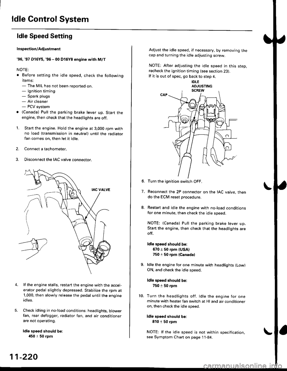
ldle Control System
ldle Speed Setting
Inspection/Adiustmenl
'96, '97 Dl6Y5. '96 - 00 Dl5Y8 sngine with M/T
NOTE:
. Before setting the idle speed, check the following
items:- The MIL has not been reported on.- lgnition timing- Spark plugs- Air cleaner- PCV system
o (Canada) Pull the parking brake lever up. Start the
engine, then check that the headlights are off.
1. Start the engine. Hold the engine at 3.000 rpm withno load (taansmission in neutral) until the radiatorfan comes on, then let it idle.
2. Connect a tachometer.
3. Disconnect the IAC valve connector.
4.lf the engine stalls, restart the engine with the accel-
erator pedal slightly depressed. Stabilize the rpm at1,000, then slowly release the pedal until the engineidles.
Check idling in no-load conditionsr headlights. blowerfan. rear defogger, radiator fan, and air conditioner
are not operating.
ldle spsed should be:
450 1 50 rpm
11-220
Adjust the idle speed, if necessary, by removing thecap and turning the idle adjusting screw.
NOTE; After adjusting the idle speed in this step,recheck the ignition timing (see section 23).
lf it is out of spec, go back to step 4.
IDLE
6. Turn the ignition switch OFF.
7. Reconnect the 2P connector on the IAC valve, then
do the ECM reset procedure.
8. Restart and idle the engine with no-load conditionsfor one minute, then check the idle speed.
NOTE: (Canada) Pull the parking brake lever up.Start the engine, then check that the headlights areoff.
ldle sp€sd should b€:
670 i 50 rpm IUSA)750 t 50 rpm {Canada}
9. ldle the engine tor one minute with headlights {Low)ON. and check the idle speed.
ldle speed should be:
750 :r 50 rpm
10. Turn the headlights off. ldle the engine for oneminute with heater fan switch at Hl and air conditioneron, then check the idle speed.
ldle speed should be:
810150 rpm
NOTE: lf the idle speed is not within specification,see Symptom Chan on page 11-84.
Page 490 of 2189
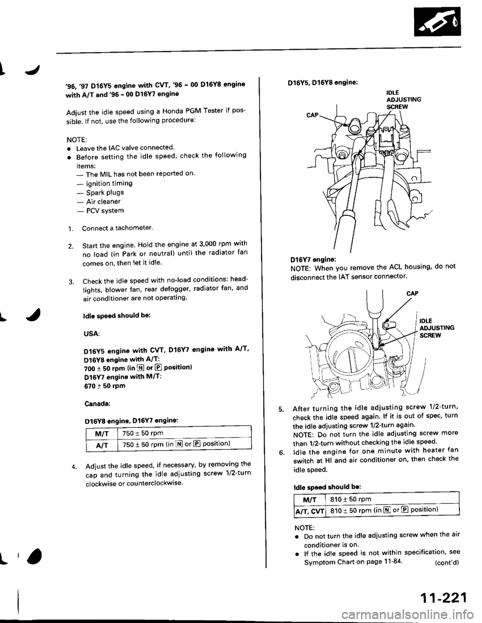
t
t
I
'96.'97 D16Y5 engine with CVT,'96 - 00 D16Y8 ongins
with A/T and'96 - 00 Dl6Y7 €ngine
Adiust the idle speed using a Honda PGM Tester if pos-
sible. lf not, use the following procedure:
NOTEI
. Leave the IAC valve connected
. Betore setting the idle speed. check the following
items:- The MIL has not been reported on'
- lgnition timing
- Spark Plugs- Air cleaner- PCV system
1. Connect a tachometer.
2. Start the engine. Hold the engine at 3,000 rpm wirh
no load (in Park or neutral) until the radiator fan
comes on, then let it idle.
3. Check the idle speed with no-load conditions: head-
iights, blower fan, rear defogger, radiator fan, and
air conditioner are not operatlng
ldl€ spoed should be:
USA:
D16Y5 engine with CVT, D16Y7 engine with A/T'
Dl6YB engine with A/T:
700 :r 50 rpm (in E or El Positionl
D16Y7 engine with M/T:
670 i 50 rpm
Canada:
Dl6Y8 sngin€, Dl6Y7 engins:
M/T750 t 50 rpm
NT750 1 50 rpm (in E or El Position)
Adjust the idle speed, if necessary, by removing the
cap and turning the idle adiusting screw 1/2-turn
clockwise or counterclockwise
D16Y5, D16Y8 engine:
IDLEADJUSTING
Dl6f, ongine:
NOTE: When you remove the ACL housing, do not
disconnect the IAT sensor connector
After turning the idle adjusting scrow 1/2-turn'
check the idle speed again. lf it is out of spec, turn
the idle adjusting screw 1/2-turn agaan'
NOTE: Do not turn the idle adjusting screw more
than 1/2-turn without checking the idle speed'
ldle the engine for one minute with heater fan
switch at Hl and air conditioner on, then check the
idle speed.
ldle speed should be:
M/T810150 rpm
A/T. CvT810 t 50 rpm (in El or E Position)
NOTE:
. Do not turn the idle adjusting screw when the air
conditioner is on.
. lf the idle speed is not within specification. see
Symptom Chart on page 11-84 (cont'd)
11-221
Page 491 of 2189
ldle Control System
ldle Speed Setting (cont'dl
Inspeqtion/Adiustment
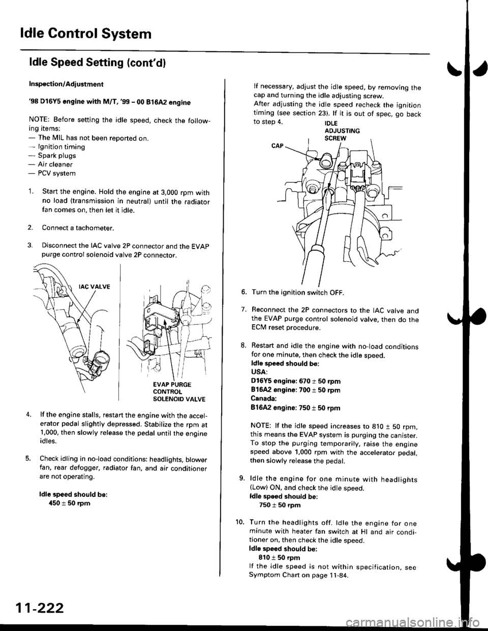
38 D16Y5 engine whh M/T,'99 - 00 81642 engine
NOTE: Before setting the idle speed, check the follow-ing items;- The MIL has not been reported on.- lgnition timing- Spark plugs- Air cleaner- PCV system
'1. Start the engine. Hold the engine at 3,000 rpm withno load (transmission in neutral) until the radiatorfan comes on, then let it idle.
Connect a tachometer.
Disconnect the IAC valve 2P connector and the EVAPpurge controlsolenoid valve 2P connector.
EVAP PURGECONTROLSOLENOID VALVE
lf the engine stalls, restart the engine with the accel-erator pedal slightly depressed. Stabilize the rpm at1.000, then slowly release the pedal until the engineidles.
Check idling in no-load conditions: headlights, blowerfan, rear defogger, radiator fan, and air conditionerare not operating.
ldl€ speed should be:
450 i 50 rpm
11-222
lf necessary, adjust the idle speed, by removrng lnecap and turning the idle adjusting screw.After adjusting the idle speed recheck the ignitlontiming (see section 23). lf it is out of spec, go backto step 4. |DLE
6. Turn the ignition switch OFF.
7. Reconnect the 2P connectors to the IAC valve andthe EVAP purge control solenoid valve, then do theECM reset procedure.
8. Restart and idle the engine with no-load conditionsfor one minute, then check the idle sDeed.ldle speed should bo:
USA:
D16Y5 engine: 670 i 50 rpm
81642 engine: 700 i 50 rpm
Canada:
81642 engine: 750 t 50 rpm
NOTE: lf the idle speed increases to 8lO t 50 rpm,this means the EVAP system is purging the canister.To stop the purging temporarily, raise the enginespeed above 1,000 rpm with the accelerator pedal,
then slowly release the pedal.
9. ldle the engine for one minute with headlights(Low) ON. and check the idle speed.
ldle speed should be:
750 i 50 rpm
10. Turn the headlights off. ldle the engine for oneminute with heater fan switch at Hl and air condi-tioner on, then check the idle soeed.ldls speed should be:
810 t 50 rpm
lf the idle speed is not within specification, seeSymptom Chart on page 11-84.
Page 492 of 2189
\
I
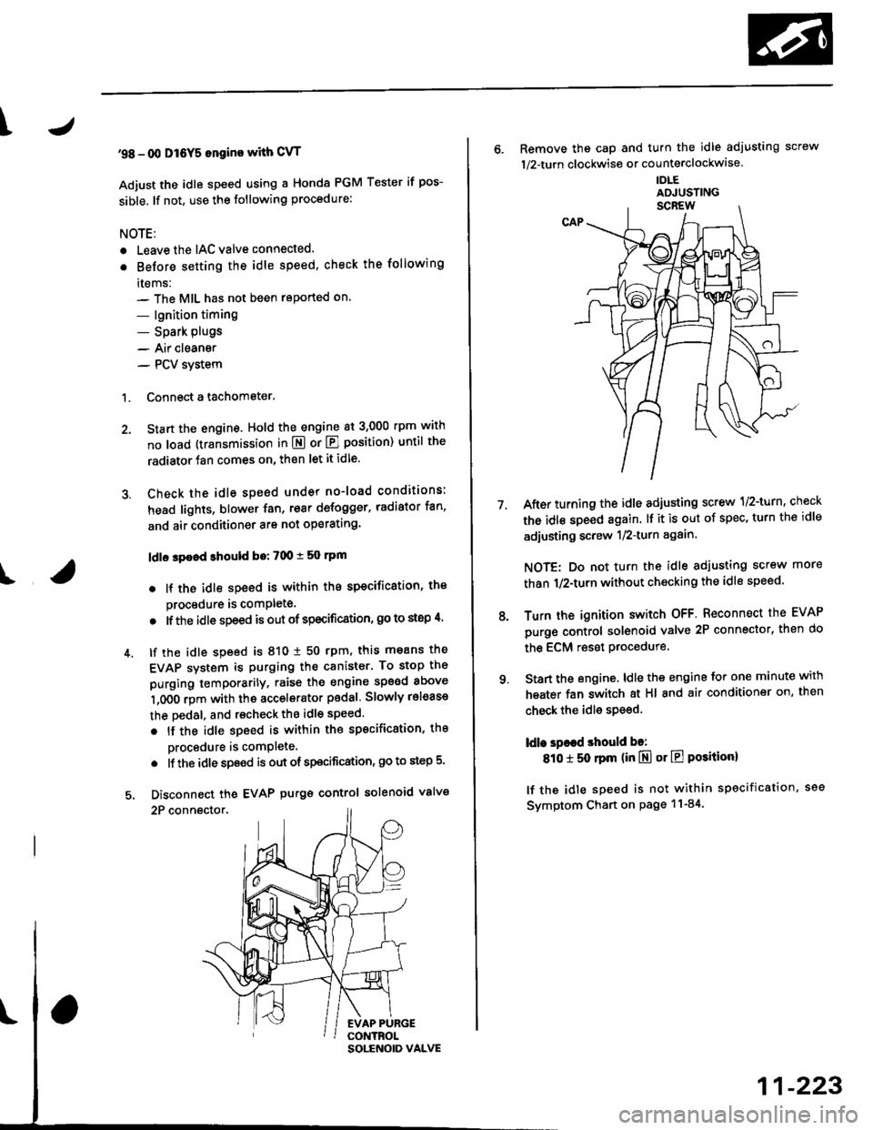
'98 - 0O D16Y5 ongine with CvT
Adjust the idle speed using a Honda PGM Tester if pos-
sible. lf not, use the following procedure:
NOTE:
. Leave the IAC valve connected.
. Before s€tting the idle speed, check the following
rtems:- The MIL has not been reported on.
- lgnition timing
- Spark Plugs- Air clean€r
- PCV svstem
'1. Connect a tachometer.
2. Stan the engine. Hold the engine at 3,000 rpm w'th
no load (transmission in E or E] position) until the
radiator Jan comes on, then let it idle.
3. Check the idle speed under no-load conditions:
head lights, blower fan, rear defogger, radiator fan,
and air conditioner are not operatlng.
ldlo spaod ehould bo: 700 t 50 rpm
. lf the idle speed is within the specification, the
procedure is comPlete.
. lf the idle sDeed is out of specitication, 9o to step 4'
4. tf the idle speed is 810 1 50 rpm, this means the
EVAP system is purging the canister. To stop the
purging temporarily, raise the engine speed above
l,OO0 rgm with the accelsrator pedal. Slowly release
the pedal. and rscheck the idl€ speed.
. tf the idle speed is within the specificstion, the
Drocedure is comPlete.
. lf the idle sp€ed is out of spocification, go to step 5.
5. Disconnect th€ EVAP purgs control solenoid valve
2P connector.
EVAP PURGECONTROL
6. Remove the cap and turn the idle adiusting screw
1/2-turn clockwise or counterclockwlse
IDLE
7.After turning the idle adjusting screw 1/2-turn, check
the idl€ speed again. lf it is out of spec, turn the idle
adjusting screw 1/2-turn again.
NOTE: Do not turn the idle adjusting screw more
than 1/2-turn without checking the idle speed.
Turn the ignition switch OFF. Reconnect the EVAP
purge control solenoid valve 2P connector' then do
the ECM reset Procedure.
Start the engine. ldle the engine for one minute with
heater fan switch at Hl and air conditioner on, then
check the idle speed.
ldle spaed should be:
810 t 50 rpm (in El or E Posiiion)
lf the idle speed is not within specification, see
Svmptom Chart on Page 11-84.
9.
SOLENOID VALVE
11-223