fork HONDA CIVIC 1996 6.G Owner's Manual
[x] Cancel search | Manufacturer: HONDA, Model Year: 1996, Model line: CIVIC, Model: HONDA CIVIC 1996 6.GPages: 2189, PDF Size: 69.39 MB
Page 643 of 2189
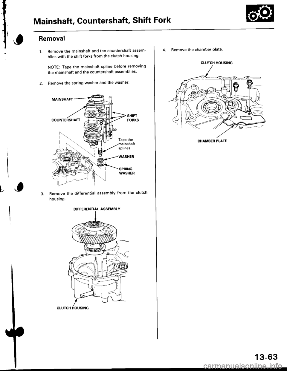
Mainshaft, Countershaft, Shift Fork
Removal
1.Remove the mainshaft and the countershaft assem-
blies with the shift forks from the clutch housing.
NOTE: Tape the mainshaft spline before removing
the mainshaft and the countershaft assemblies.
Remove the spring washer and the washer'
v
MAINSHAFT
COUNTERSHAFT
Remove the differential assembly from the clutch
housing.
Tape the
splrnes.
WASHER
DIFF€RENTIAL ASSEMBLY
4. Remove the chamber Plate.
CLUTCH HOUSING
CHAMEEF PLATE
CLUTCH HOUSING
13-63
Page 645 of 2189
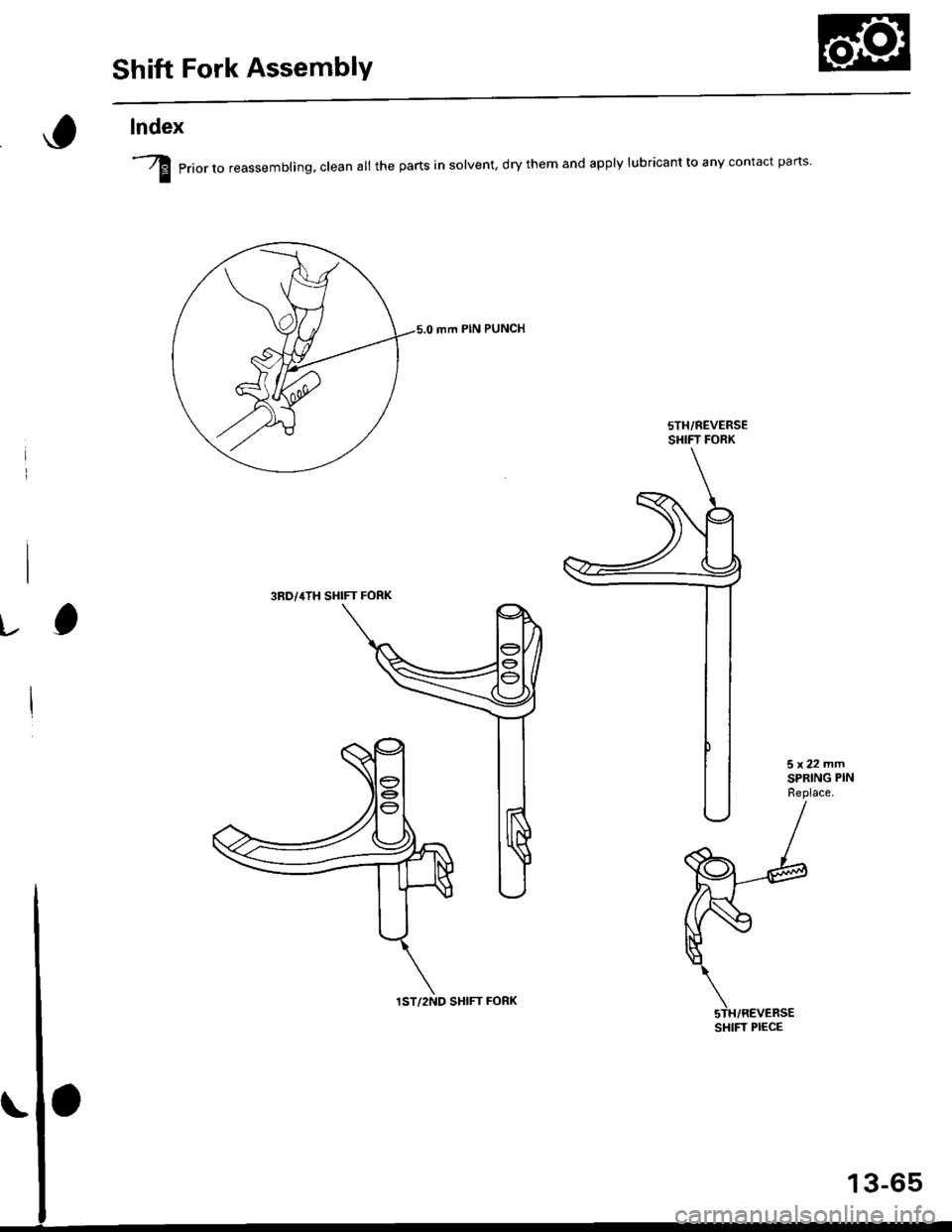
Shift Fork AssemblY
lndex
-A erior ro reassemblinq. clean all the parts in solvent, dry them and apply lubricant to any contact pans
I
mm PIN PUNCH
sTH/REVERSESI{IFT FORK
3RD/4TH SHIFT FORK
Page 646 of 2189
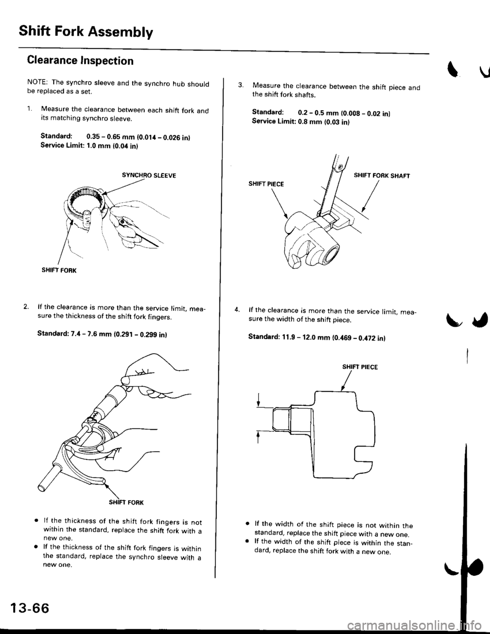
Shift Fork Assembly
Clearance Inspection
NOTE: The synchro sleeve and the synchro hub shouldbe replaced as a set.
1. Measure the clearance between each shift fork andits matching synchro sleeve.
Standard: 0.35 - 0.65 mm {O.Olit - 0.026 inlService Limit: 1.0 mm t0.04 inl
SHIFT FOBK
lf the clearance is more than the service limit. mea_sure the thickness of the shitt fork finoers.
Standard: 7.4 - 7.6 mm (0.291 - 0.299 in)
lf the thickness of the shift fork frngers rs notwithin the standard, replace the shift fork with anew one.
lf the thickness of the shift fork fingers is withinthe standard, replace the synchro sleeve with a
13-66
3. Measure the clearance between the shift piece andthe shift fork shafts.
Standard: 0.2 - 0.5 mm (0.008 - 0.02 inlService Limit: 0.8 mm {0.03 in)
lf the clearance is more than the service limit. mea-sure the width of the shift Diece.
Standard: 11.9 - 12.0 mm (0.469 - 0.it72 in)
lf the width of the shift piece is not within thestandard, replace the shift piece with a new one.lf the width of the shift piece is within the stan_dard, replace the shift fork with a new one.
t,
SHIFT PIECE
Page 671 of 2189
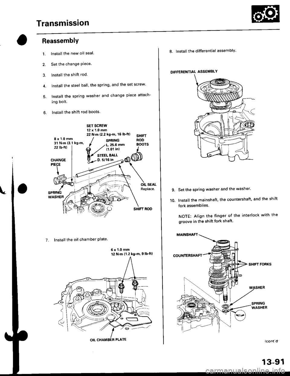
Transmission
ReassemblY
1. Install the new oil seal
2. Set the change Piece.
3. Install the shift rod
4. Install the steel ball' the spring, and the set screw'
5. Install the spring washer and change piece attach-
ing bolt.
6. Install the shift rod boots.
8x1.0mm31 N.m 13.1 kg-m,22lb-ltl
CHANGEPIECE
@:4OIL SEALReplace.SPRINGWASHER
7. Install the oil chamber Plate'
6 x '1.0 mm12 N.m (1.2 kg-m,9lb-ft|
SPRING
, /L.256fim B()(
@ / t't o'ti"l I
{zw"y-6@
q
10.
Set the spring washer and the washer'
lnstall the mainshaft, the countershaft, and the shift
fork assemblies.
NOTE: Align the finger of the interlock with the
groove in the shift fork shaft.
SHIFT FORKS
13-91
Page 681 of 2189

Description
The automatic transmission is a 3-element torque converter and a dual-shaft electronically controlled unit which provides
4 soeeds forward and 1 reverse.
Torque Convertel, Geats, and Clutches
The torque converter consists of a pump, turbine and stator, assembled in a single unit. They are connected to the engine
crankshaft so they turn together as a unit as the engine turns. Around the outside of the torque converter is a ring gear
which meshes with the starter pinion when the engine is being started. The entire torque converter assembly seryes as a
flywheel while transmiuing power to the transmission mainshaft.
The transmission has two parallel shafts: the mainshaft and the countershaft. The mainshaft is in Iine with the engine
crankshaft. The mainshaft includes the 1st, 2nd and 4th clutches, gears tor 2nd, 4th, reverse and lst (3rd gear is integral
with the mainshaft, while the reverse gear is integral with the 4th gear). The countershaft includes the 3rd clutch, and
gears for 3rd,2nd, 4th, reverse. 1st and park. The gears on the mainshaft are in constant mesh with those on the counter-
shaft. When certain combinations of gears in transmission are engaged by clutches. power is transmitted from the main-
shaft to the countershaft to provide E, ld, E, and E positions.
Electronic Control
The electronic control svstem consists of the Powertrain Control Module {PCM), sensors, a linear solenoid and four
solenojd valves. Shifting and lock-up are electronically controlled for comtonable driving under all conditions. The PCM is
located below the dashboard, under the front lower panel on the passenger's side
Hydraulic Control
The valve bodies include the main vatve body, the secondary valve body, the regulator valve body, the servo body and the
lock-up valve body through the respective separator plates, They are bolted on the torque converter housang
The main valve body contains the manual valve, the 1-2 shift valve. the 2nd orifice control valve, the CPB {Clutch Pressure
Back-up) valve, the modulator valve. the servo control valve, the relief valve, and ATF pump gears The secondary valve
body contains the 2-3 shift valve. the 3-4 shift valve, the 3-4 orifice control valve, the 4th exhaust valve and the CPC (Clutch
pressure Control) valve. The regulator valve body contains the pressure regulator valve, the torque converter check valve,
the cooler relief valve, and the lock-up control valve. The servo body contains the servo valve which is integrated with the
reverse shift fork, and the accumulators. The lock-up valve body contains the lock-up shift valve and the lock-up timing
valve. The linear solenoid and the shift control solenoid valve Ay'B are bolted on the outside of the transmission housing,
and the lock-up control solenoid valve Ay'B is bolted on the outside of the torque converter housing. Fluid from regulator
passes through the manual valve to the various control valves. The clutches receive fluid from their respective teed pipes
or internal hydraulic circuit.
Shift Control Mechanism
Input from various sensors located throughout the car determines which shift control solenoid valve the PCM will activate
Activating a shift control solenoid valve changes modulator pressure, causing a shift valve to move. This pressurizes a line
to one of the clutches, engaging that clutch and its corresponding gear, The shift control solenoid valves A and B are con-
trolled by the PCM.
Lock-up Mechanism
In ,Dt1 position, in 3rd and 4th. and in E position in 3rd, pressurized fluid is drained from the back of the torque converter
through a fluid passage, causing the lock-up piston to be held against the torque converter cover. As this takes place, the
mainshaft rotates at the same as the engine crankshaft. Together with hydraulic control, the PCM optimizes the timing of
the lock-up mechanism. The lock-up valves control the range of lock-up according to lock-up control solenoid valves A and
B, and linear solenoid. When lock-up control solenoid valves A and B activate, the modulator pressure changes The lock-
up control solenoid valves A and B and the linear solenoid are controlled by the PCM.
(cont'd)
14-3
Page 690 of 2189
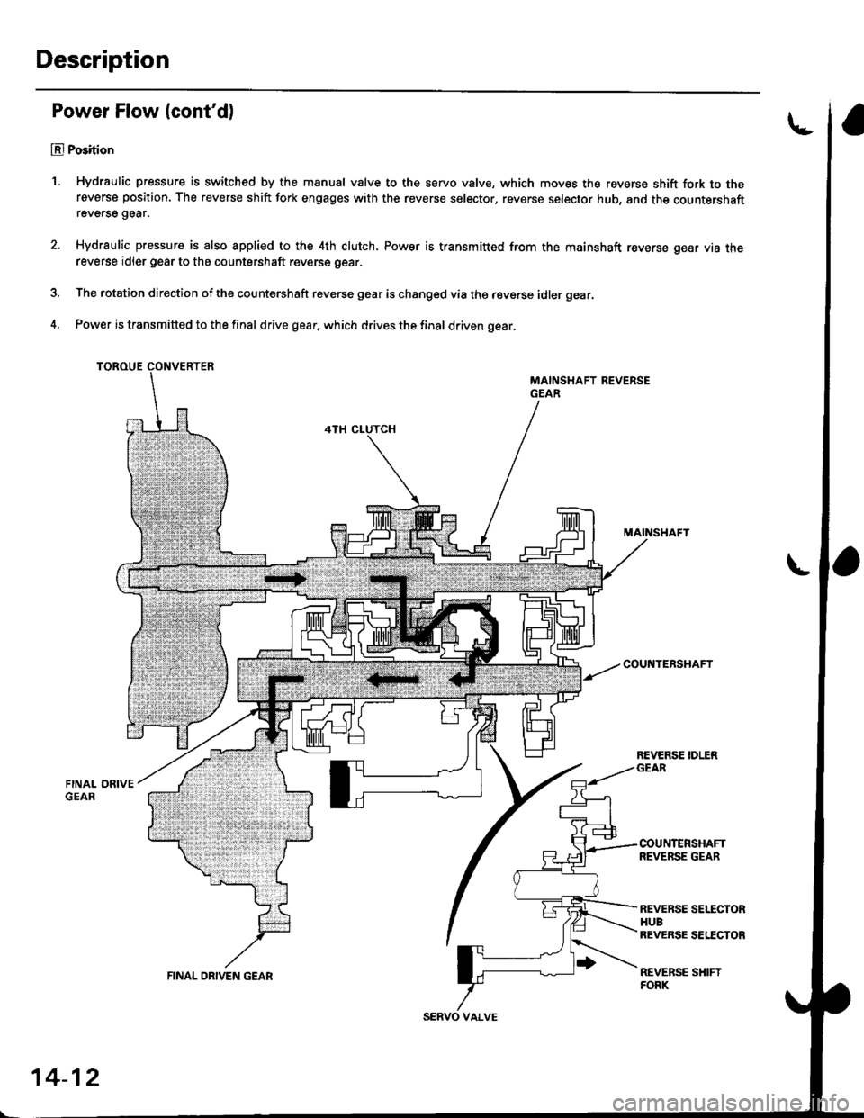
Description
Power Flow (cont'd)
El Po3ition
1, Hydraulic pressure is switched by the manual valve to the servo valve, which moves the reverse shift fork to thereverse position. The reverse shift fork engages with the reverse selector, reverse selector hub, and the countershaftreverse gear.
Hydraulic pressure is also applied to the 4th clutch. Power is transmitt€d from the mainshaft reverse gear via thereverse idler gear to the countershaft reverse gear.
The rotation direction of the countershaft reverse gear is changed via the reverse idler gear,
Power is transmitted to the final drive gear, which drives the final driven gear.
TOROUE
MAINSHAFT
COU TERSHAFT
REVERSE SELECTORHUBREVERSE SETICTOR
REVERSE SHIFTFORK
REVERSE IDLER
14-12
FINAL ON|VEN GEAR
Page 701 of 2189
\
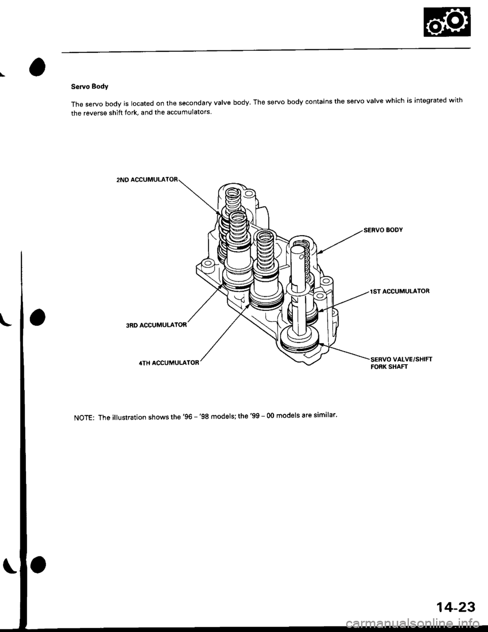
Servo Body
The servo body is located on the secondary valve body. The servo body contains the servo valve which is integrated with
the reverse shift fork, and the accumulators
2NO ACCUMULA
SERVO BODY
1ST ACCUMULATOR
3RD ACCUMULATOR
SERVO VALVE/SHIFTFORK SHAFT
NoTE: The illustration shows the'96 - '98 models; the '99 - 00 models are similar'
14-23
Page 789 of 2189
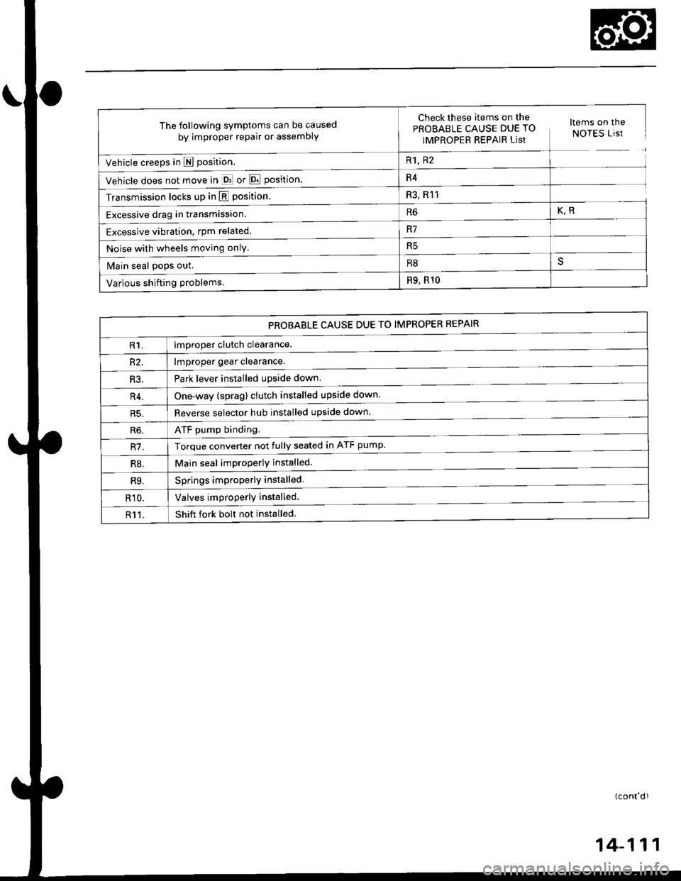
The following symptoms can be caused
by improper repair or assembly
Check these items,on th€^ ltems on thePROBABLE CAUSE DUE TO NOTES ListIMPROPER REPAIR List
Vehicle creeps in N position.R1, R2
Vehicle does not move in &l or Pll position.R4
Transmission locks up in E position.R3, R11
Excessive drag in transmission.R6K,R
Excessive vibration, rpm related.R7
Noise with wheels moving onlY.R5
Main seal pops out.R8
Various shifting problems.R9, RlO
PROBABLE CAUSE DUE TO IMPROPER REPAIR
lmproper clutch clearance.
lmproper gear clearance.
Park lever installed upside down.
one-way {sprag) clutch installed upside down.
Reverse selector hub installed upside down.
ATF pump binding.
Torque converter not fully seated in ATF pump.
Main seal improperly installed.
Springs improperly installed.
Valves improperly installed.
Shift fork bolt not installed.
14-11
Page 790 of 2189
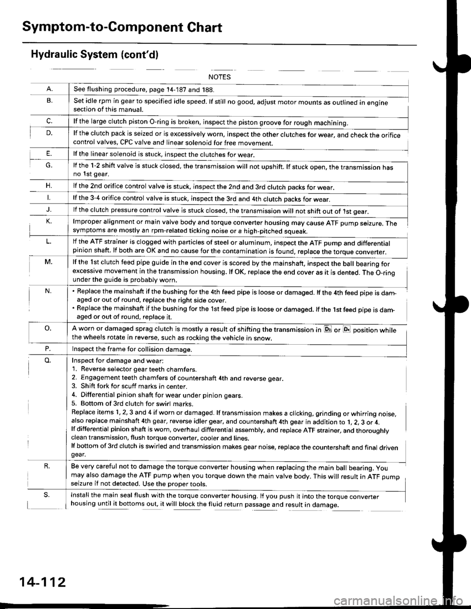
Symptom-to-Component Chart
Hydraulic System (cont'dl
G.
n,
set idle rpm in gear to specified idle speed. lf still no good, adjust motor mounts as outlined in enginesection of this manual.
lf the clutch pack is seized or is excessively worn. inspect the other clutches for wear, and check the orificecontrol valves, CPC valve and linear solenoid for free movement.
lf the linear solenoid is stuck, inspect the clutches for wear.
lmproper alignment or main valve body and torque converter housing may cause ATF pump seizure. Thesymptoms are mostly an rpm-related ticking noise or a high-pitched squeak.
lf the l st clutch feed pipe guide in the end cover is scored by the mainshaft, inspect the ball bearing forexcessive movement in the transmission housing. lf oK, replace the end cover as it is dented. The o-rinounder the guide is probably worn.
Replace the mainshaft if the bushing for the 4th feed pipe is loose or damaged. lf the 4th feed pipe is danFaged or out of round, replace the right side cover.
Replace the mainshaft if the bushing for the 1st feed pipe is loose or damaged. lf the 1st feed pipe is darn-aged or out of round, replace it.
A worn or damaged sprag clutch is mostly a result of shifting the transmission inthe wheels rotate in reverse, such as rocking the vehicle in snow.
or E position while
Inspect for damage and wear:
1. Reverse selector gear teeth chamfers.
2. Engagement teeth chamfers of countershaft 4th and reverse gear.
3. Shift fork for scuff marks in center.
4. Differential pinion shaft for wear u nder pin ion gears.
5. Bottom of 3rd clutch for swirl marks.
Replace items 1,2,3 and 4 if worn or damaged. lf transmission makes a clicking, grinding orwhirring noise,also replace mainshaft 4th gear, reverse idler gear. and countershaft 4th gear in addition to 1, 2, 3 or 4.lf differential pinion shaft is worn, overhaul differential assembly, and replace ATF strainer, and thoroughlyclean transmission, flush torque converter, cooler and lines.lf bottom of 3rd clutch is swirled and transmission makes gear noise, replace the countershaft and final drivengear.
Be very careful not to damage the torque converter housing when replacing the main ball bearing, you
may also damage the ATF pump when you torque down the main valve body. This will result in ATF pumpseizure if not detected. Use the oroper roors.
Install the main seal flush with the torque converter housing. lf you push it into the torque converterhousing until it bottoms out, it will block the fluid return passage and result in damage.
See flushing procedure, page 14-187 and 188.
lf the large clutch piston O-ring is broken, inspect the piston groove for rough machining.
lf the l-2 shift valve is stuck closed, the transmission will not upshift. lf stuck open, the transmission hasno 1st gear.
lf the znd orifice control valve is stuck. inspect the 2nd and 3rd clutch oacks for wear.
lf the 3-4 orifice control valve is stuck, inspect the 3rd and 4th clutch oacks for wear.
lf the clutch pressure control valve is stuck closed, the transmission will not shift out of 1st gear.
lf the ATF strainer is clogged with particles of steel or aluminum, inspect the ATF pump and differentialpinion shaft. lf both are OK and no cause for the contamination is found, replace the torque converter.
Inspect the frame for collision damage.
14-112
Page 802 of 2189
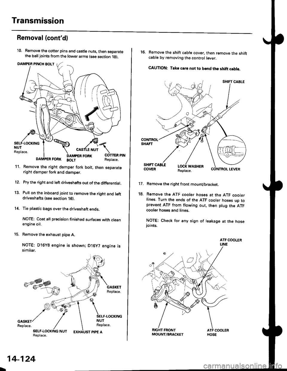
Transmission
Removal(cont'd)
'10. Remove the cotter pins and castle nuts, th€n separatethe balljoints from the lower arms (see section 1gl.
DAMPER PINCH BOLT
NUT
FORI(FORK BOLT
11. Remove the right damper fork bolt. th€nright damper fork and dampor.
COTTER PINReplace.
separate
12.
1a
14.
Pry the right and left driveshafts out ofthe differential.
Pull on the inboard joint to remove the right and leftdrivsshafts (see section 16).
Tie plastic bags over the driveshaft onds.
NOTE: Coat all precision finished surfaces with cleanengine oil.
Remove the exhaust pipe A,
NOTE: Dl6YB engine is shown; D16y7 engine issimilar.
t9.
SELF-LOCKING NUTReplace.
L
14-124
EXHAUST PIPE AMOUNT/BRACKET
17.
18.
16. Remove the shift cable cover. then remove the shiftcable by removing the control lever,
CAUTION: Take car6 not to bond the shift cable.
Remove the right front mounvbracket.
Remove the ATF cooler hoses at the ATF coolerlines. Tufn the ends of the ATF cooler hoses uo toprevent ATF from flowing out, then plug the ATFcooler hosgs and lines.
NOTE: Check for any sign of leakage at the hoseioints.
WASHER