fork HONDA CIVIC 1996 6.G User Guide
[x] Cancel search | Manufacturer: HONDA, Model Year: 1996, Model line: CIVIC, Model: HONDA CIVIC 1996 6.GPages: 2189, PDF Size: 69.39 MB
Page 591 of 2189
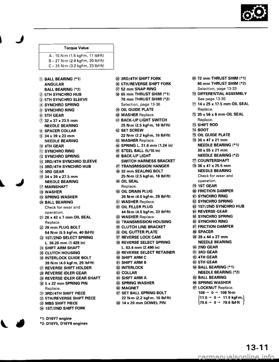
Torque Value
A - 15 N.m (1.5 kgf.m, 1'1 lbf.ft)
B - 27 N.m (2.8 kgf.m. 20 lbift)
C - 31 N.m {3.2 kgnm, 23 lbift)
\
O BALL BEARING (*T)
ANGULAR
BALL BEARING {*2I
O 5TH SYNCHRO HUB
O 5TH SYNCHRO SLEEVE
€) SYNCHRO SPRING
o SYNCHRO B|NG
@ 5TH GEAR
@ gz xgt x 23.5 mm
NEEDLE BEARING
@ SPACER COLLAR
@34x39x23mm
NEEDLE BEARING
(D 4TH GEAR
O SYNCHRO RING
C) SYNCHRO SPRING
CO 3RD/4TH SYNCHRO SLEEVE
@ 3RD/4TH SYNCHRO HUB
(} 3RD GEAR
@34x39x27.5mmNEEDLE BEARING
G) MAINSHAFT
G) WASHER
@ SPRING WASHER
@ BALL BEARING
Check for wear and
operation.(E 26x42x7 mm OIL SEAL
Replace.
@ 28 mm PLUG BOLT
5,1 N.m {5.5 kgf'm, /t0 lbt'ft)
@ lsT/zND SELECT SPRING
L. 36.26 mm (1./P8 in)
@ SHIFT ARM SHAFT
@ CLUTCH HOUSING
@ INTEELOCK GUIDE BOLT
39 N.m (4.0 kgf.m, 29 lbf.ftl
@ REVERSE SHIFT HOLDER
@ REVERSE IDLER GEAR
@ REVERSE IDLER GEAR SHAFT
@ 5 x 22 mm SPRING PIN
Replace.
@ 3RD/4TH SHIFT PIECE
@ 5TH/REVERSE SHIFT PIECE
@ MBS SHIFT PIECE
@ 1ST/2ND SHIFI FORK
*1:D16Y7 engine*2: D16Y5, D16Y8 engines
@ 3RD//|TH SHIFT FORK
@ 5TH/REVERSE SHIFT FORK
@ 52 mm SNAP RING
@ 65 mm THRUST SHIM (*11
70 mm THRUST SHIM (*21
Selection, page 13-36
@ OIL GUIDE PLATE
@ wASHER Replace.
@ BACK.UP LIGHT SWITCH
25 N.m (2.5 kgf'm, 18 lbf'ft)
@ sET SCREW
22 N.m {2.2 kgf.m, 16 lbl.ft}
@ WASHER Replace.
@D SPRING 1.31.6 mm (1.2,1inl
@ STEEL BALL 15/16 in)
@ BACK-UP LIGHT
SWITCH HARNESS BRACKET
@ TRANSMISSION HANGER
@ 32 MM SEALING BOLT
25 N.m (2.5 kgf.m, 18 lbt'ft)
@ OIL SEAL
Replace.
@ OIL DRAIN PLUG
39 N.m (4.0 kgf.m, 29 lbf.ft)
@ WASHER Replace.
@} OIL FILLER PLUG
44 N.m (4.5 kgf.m, 33 lbf'ftl
@ WASHER Replace.
@) TRANSMISSION HOUSING
€) CLUTCH LINE BRACKET
@ OIL GUTTER PLATE
@ REVERSE LOCK CAM
@ REVEBSE SELECT SPRING
L. 63.4 mm {2.,196 in)
@ REVERSE SELECT RETAINER
@ SHIFT ARM C
@ SHIFT ARM B
@ INTERLoCK
@ COLLAR
@ SHIFT ARM A
@ SPRING WASHER
@ MAGNET
@ sET BALL SPRING BOLT
22 N.m (2.2 kgf.m, 16 lbf.ftl
@ 14 x 20 mm DOWEL PIN
@ 72 mm THRUST SHIM l*11
80 mm THRUST SHIM (*21
Selection, page '13-33
@ DIFFERENTIAL ASSEMBLY
See page 13-30
@ 14 x 25 x 17.5 mm OIL SEAL
Replace.
@ 35 x 56 x 8 mm OIL SEAL
Replace.
@ SHIFT ROD
@ BOOr
@ OIL GUIDE PLATE
@30x47x21 mm
NEEDLE BEARING (* 1}
30x55x21 mm
NEEDLE BEARING {'2)
@ COUNTERSHAFT
@36x41 x 25.5 mm
NEEDLE BEARING
Check for wear and
operatron.
@ lsT GEAR
@ FRICTION DAMPER
@ SYNCHRO RING
@ SYNCHRO SPRTNG
@ lST/2ND SYNCHRO HUB
@ REVERSE GEAR
@ SYNCHRO SPRING
@ SYNCHRO RING
@ FRICTION DAMPER
@ SPACER
@39x4lx27mm
NEEDLE BEARING
@ 2ND GEAR
@ 3RD GEAR
@ 4TH GEAR
@ sTH GEAR
@) BALL BEARING {* 1}
NEEDLE BEARING (*2}
@ BALL BEARING
@) SPRING WASHER
@ LoCKNUT Replace.
108 - 0- 108 N.m
ftt.o* o- 1r.o kst.m,l
179.6- 0- 79.6 rbtft I
13-1 1
Page 593 of 2189
Reverse Shift Holder
)
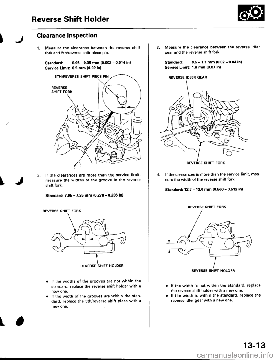
Glearance Inspection
1.Measure the clearance between the reverse shift
fork and sth/reverse shift piece pin.
Standard: 0.05 - 0.35 mm 10.002 - 0.01,1 inl
Service Limit 0.5 mm (0.02 in)
lf the clearances are more than the service limit.
measure the widths of the groove in the reverse
shifi fork.
Standard: 7.05 - 7.25 mm (0.278 - 0.285 inl
lf the widths of the grooves are not within the
standard, replace the reverse shift holder with a
new one.
lf the width of the grooves are within the stan-
dard, replace the sth/reverse shift piece with a
new one,
\
t
REVERSE
REVERSE SHIFT HOLDER
3. Measure the clearance between the reverse idler
gear and the reverse shift fork.
Standard: 0.5- 1.1 mm {0.02 - 0.0,1in)
Service Limii: 1.8 mm 10.07 inl
REVERSE IDLER GEAR
lf the clgarances is more than thg service limit, mea-
sure the width of the reverse shift fork.
Standlrd: 12.7 - 13.0 mm {0.5110 - 0.512 in}
lf the width is not within the standard, replace
the reverse shift holder with a new one.
lf the width is within the standard, replace the
revsrse idler gear with a new one.
REV€RSE SHIFT FORK
REVERSE SHIFT FORK
REVERSE SHIFT HOLOER
13-13
Page 594 of 2189
Reverse ldler Gear
Mainshaft, Cou ntershaft,
Shift Fork
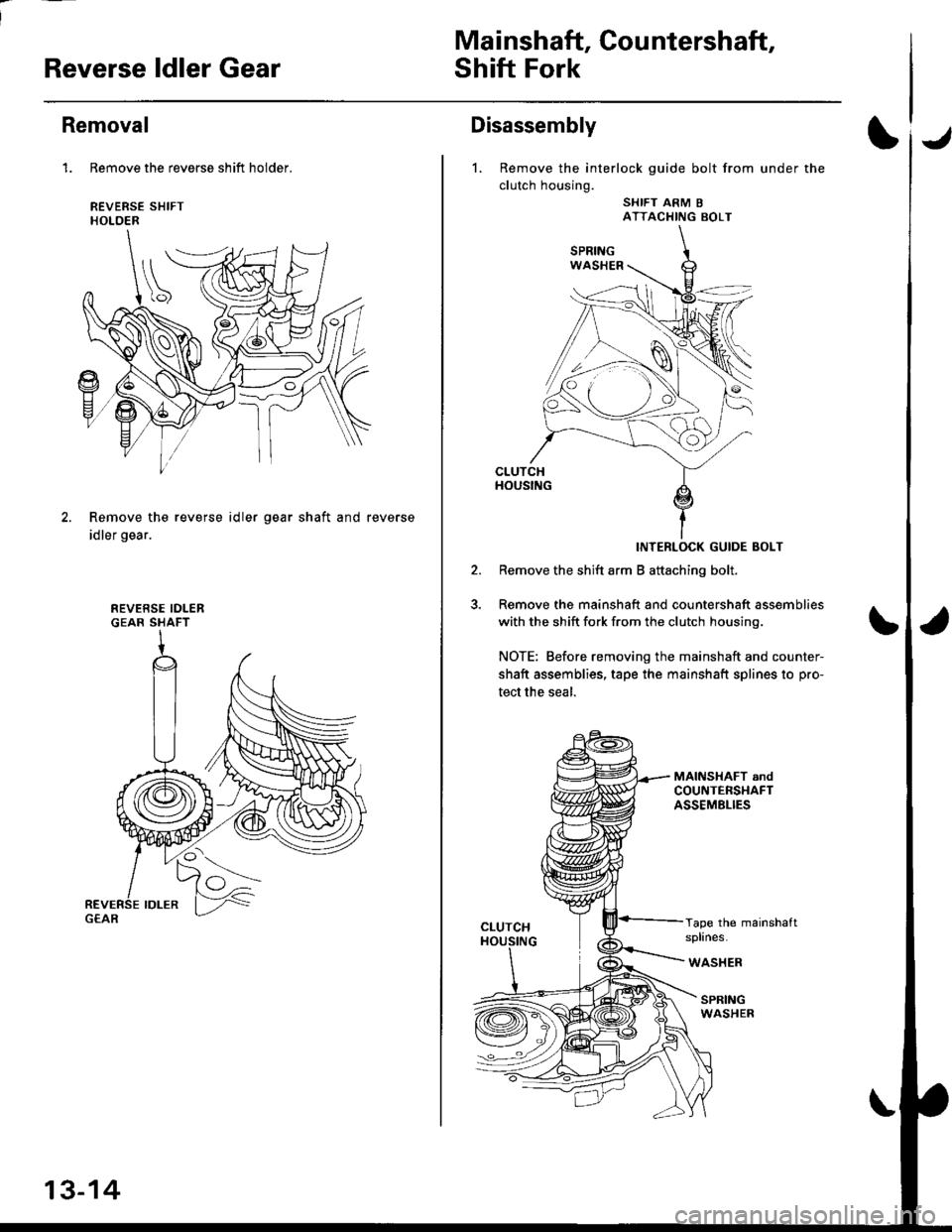
Removal
1. Remove the reverse shift holder.
REVERSE SHIFTHOLOER
Remove the reverse id ler
idler gear.
gear shaft and reverse
REVERSE IDLERGEAR SHAFT
13-14
Disassembly
1. Remove the interlock guide bolt from under the
clutch housing.
SHIFT ARM 8ATTACHING BOLT
CLUTCHHOUSING
INTERLOCK GUIDE BOLT
Remove the shift arm B attaching bolt.
Remove the mainshaft and countershaft assemblies
with the shift fork from the clutch housinq.
NOTE: Before removing the mainshaft and counter-
shaft assemblies, tape the mainshaft splines to pro-
tect the seal.
Tape the mainshaftsplines.
WASHER
SPRINGWASHER
Page 605 of 2189
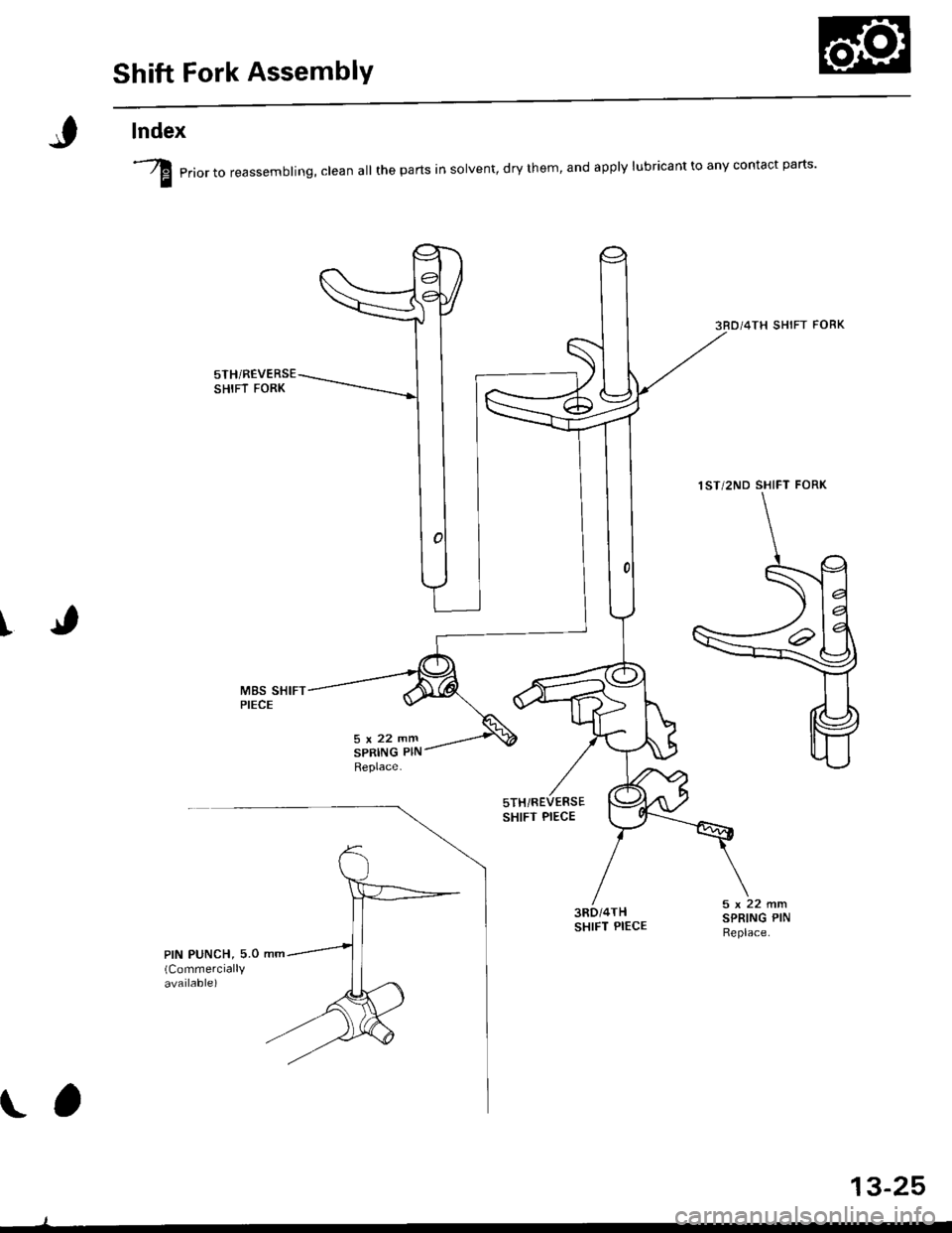
Shift Fork AssemblY
lndex
I
I erio, ,o reassembling, clean all the parts in solvent, dry them, and apply lubricant to any contact parts'
3RD/4TH SHIFT FORK
5THi REVERSESHIFT FORK
5TH/REVERSESHIFT PIECE
M8S SHIFTPIECE
3RD/4THSHIFT PIECE
1ST/2ND SHIFT FORK
\a
13-25
Page 606 of 2189
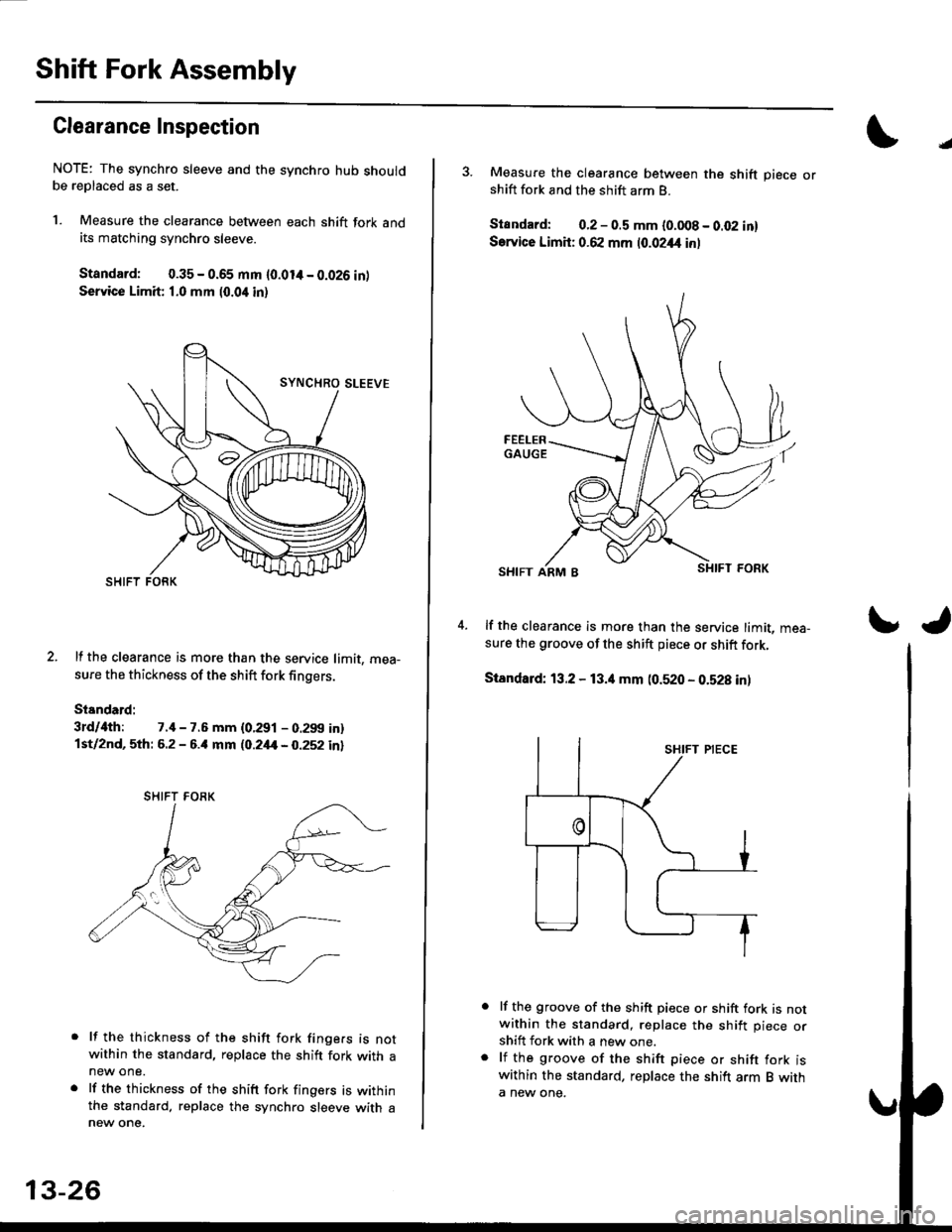
Shift Fork Assembly
Clearance Inspection
NOTE: The synchro sleeve and the synchro hub shouldbe replaced as a set.
l. Measure the clearance between each shift fork andits matching synchro sleeve.
Standard: 0.35 - 0.65 mm {0.014 - 0.026 intService Limit 1.0 mm (0.04 in)
2. lf the clearance is more than the service limit, mea-
sure the thickness of the shift fork fingers.
Standard:
3rd/ilth: 7.il - 7.6 mm {0.291 - 0.299 in}lst/2nd, 5th: 6.2 - 6.il mm (O.2,tt - 0.252 in)
lf the thickness of the shift fork finge.s is notwithin the standard, replace the shift fork with anew one.
lf the thickness of the shift fork fingers is withinthe standard. replace the synchro sleeve with a
SHIFT FORK
13-26
J
3. Measure the clearance between the shift piece orshift fork and the shift arm B.
Standard: 0.2 - 0.5 mm {0.008 - 0.02 in}
Sarvice Limit: 0.62 mm 10.0244 inl
4. lf the clearance is more than the service limit, mea-sure the groove of the shift piece or shift fork,
Standard: 13.2 - 13.4 mm (0.520 - 0.b28 inl
lf the groove of the shift piece or shift fork is notwithin the standard, replace the shift piece orshift fork with a new one.
lf the groove of the shift piece or shift fork iswithin the standard, replace the shift arm B witha new one.
\J
Page 620 of 2189
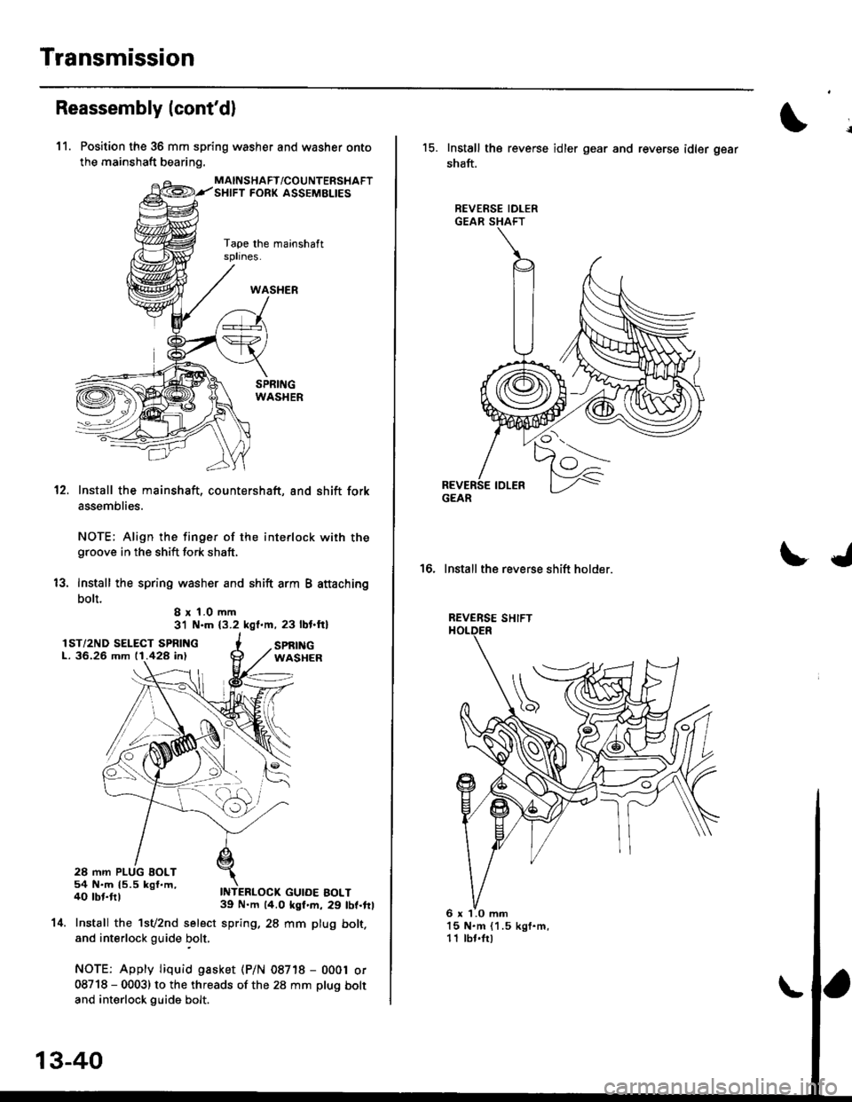
Transmission
Reassembly lcont'dl
11. Position the 36 mm spring washer and washer onto
the mainshaft bearing.
MAINSHAFT/COUNTERSHAFTSHIFT FORK ASSEMELIES
Tape the mainshaftsplines.
12.
13.
Install the mainshaft, countershaft, and shift fork
assemblies.
NOTE; Align the finger of the interlock with thegroove in the shift fork shaft,
lnstall the spring washer and shift arm B attaching
bolt.I x 1.0 mm31 N.m (3.2 kgl.m, 23 lbt.ft)
IST/2ND SELECT SPRINGL. 36.26 mm 11.428 in)
54 N.m 15.5 kgf.m,40 tbt.ftl
SPf,INGWASHER
GUIDE BOLT
14.
39 N.m 14.0 kgf.m, 29 lbf.frl
Install the 1sv2nd select spring, 28 mm plug bolt.
and interlock guide bolt,
NOTE: Apply Iiquid gasket (P/N 08718 - 0001 or
08718 - 0003) to the threads of the 28 mm plug bolt
and interlock guide bolt.
13-40
15. Install the reverse idler gear and reverse idler gear
shaft.
REVERSE IDLERGEAR SHAFT
LJ16. Install the reverse shift holder.
REVERSE SHIFT
l5 N.m (1.5 kgf.m,11 lbt.trl
GEAR
6 x 1.0 mm
Page 625 of 2189
S4C Model ('99 - 00 2-door Si, SiR)
Manual Transmission
Special Tools ............' 13-46
Maintenance
Transmission Oi1 ...................'.......... 13-47
Back-up Light Switch
Repfacement ...""" 13'47
Transmission Assembly
Removal ......'.......... 13-/tB
lnstallation ............. 13-52
lllustrated lndex ................................... 13-54
Transmission Housing
Removal ................. 13-55
Beverse Shift Holder, Reverse ldler Gear
Clearance lnspection ...................".. 13-57
Removal ................. 13-58
Change Holder Assembly
Clearance lnspection .................".... 13-59
Removal ....,,........... 13-61
Disassembly/Reassembly ............... 1 3-62
Mainshaft, Countershaft, Shift Fork
Removal ................. 13-63
Shift Rod
Removal .........."'.... 13-64
Shift Fork Assembly
lndex ................ ...... 13-65
Clearance lnspection .............'......... 13'66
Mainshaft Assembly
lndex ............"" ...... 13-67
Clearance lnspection ....................... 13-68
Disassembly .......... 13-71
fnspection '."'.......', 13'72
Reassembly .......'... 13-73
Countershaft Assembly
fndex ................ "....13-71
Glearance Inspection'......'...........'... 1 3'75
Disassembly .......... 13-76
fnspection .'............13'77
Reassembly "......... 13'78
Synchro Sleeve, Synchro Hub
Inspection .............. 13'8C
Installation ............. 13-80
Synchro Ring, Gear
Inspection .'............ 13-81
Differential
lndex ................ ...... 13-82
Backlash Inspection ..."..........."'...... 1 3-82
Final Driven Gear Replacement ...... 13-83
Bearing Replacement ....."'.......""'.. 13-83
Thrust Shim Adiustment ......""'..... 13-84
Clutch Housing Bearing
Replacement ..'...... 13-86
Mainshaft Thrust Glearance
Adiustment '.........'. 13-88
Transmission
Reassembly ."'....... 13-91
Oil Seals
Replacement ..'...... 13-96
Gearshift Mechanism
Overhaul ................ 13-97
\
Page 629 of 2189
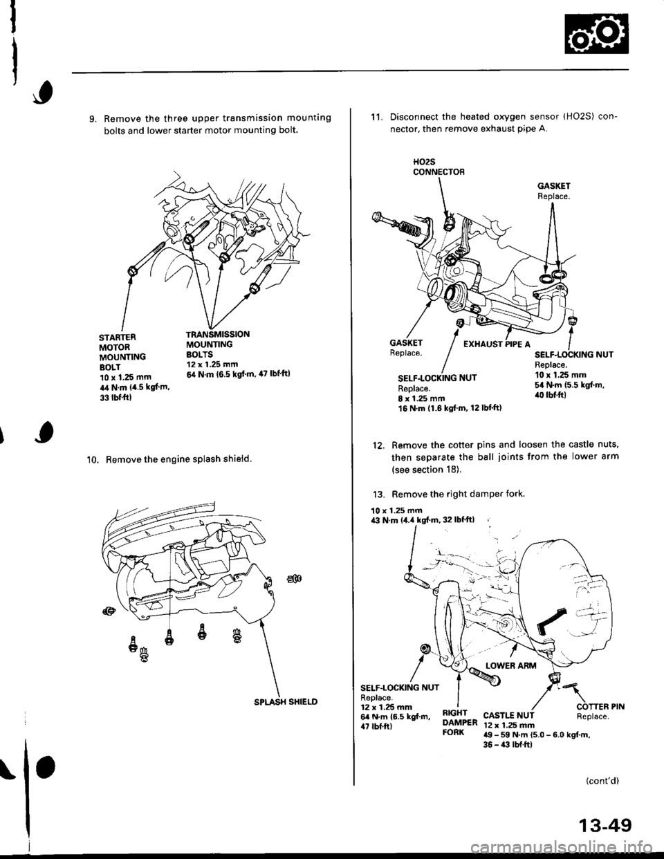
9. Remove the three upper transmission mounting
bolts and lower starter motor mounting bolt.
'10. Remove the engine splash shieid.
TRANSMISSIONMOUNTINGBOLTS12 x 1.25 mm
6,1 N.m (6.5 kgd m, 47 lbf'ft|
STARTERMOTORMOUNTINGBOLT10 x 1.25 mm
a,t N.m 14.5 kgl.m.
33 tbf.trl
CONNECTOE
11. Disconnect the heated oxygen sensor (HO2S) con-
nector, then remove exhaust pip€ A.
H02S
SELF.LOCKING NUTReplace.8 r 1.25 mm16 N.m (1.6 kgf.m, 12lbf'ft)
Replace.10 x 1,25 mm54 N.m {5.5 kgf.m,'lll lbf.ft)
12. Remove the cotter pins and loosen the castle nuts,
then separate the ball joints from the lower arm
(see section 18).
13. Remove the right damPer fork.
10 x 1.25 mma3 N.m lil.a kgf.m, 32 lbf'ft| ,
SELF.LOCKING NUTR6place.12 x 1.25 mm6a N.m (6.5 kgl.m,47 rbf ft)
RIGHTDAMPERFORK
CASTI.T NUT12 x 1,25 mma9 - 59 N.m (5.0 - 6.0 kgtm,36 - i(t lbf.ftl
(cont'd)
!-
ria -11: \/-/
't'''-a
SPLASH SHIELD
13-49
Page 632 of 2189
Transmission Assembly
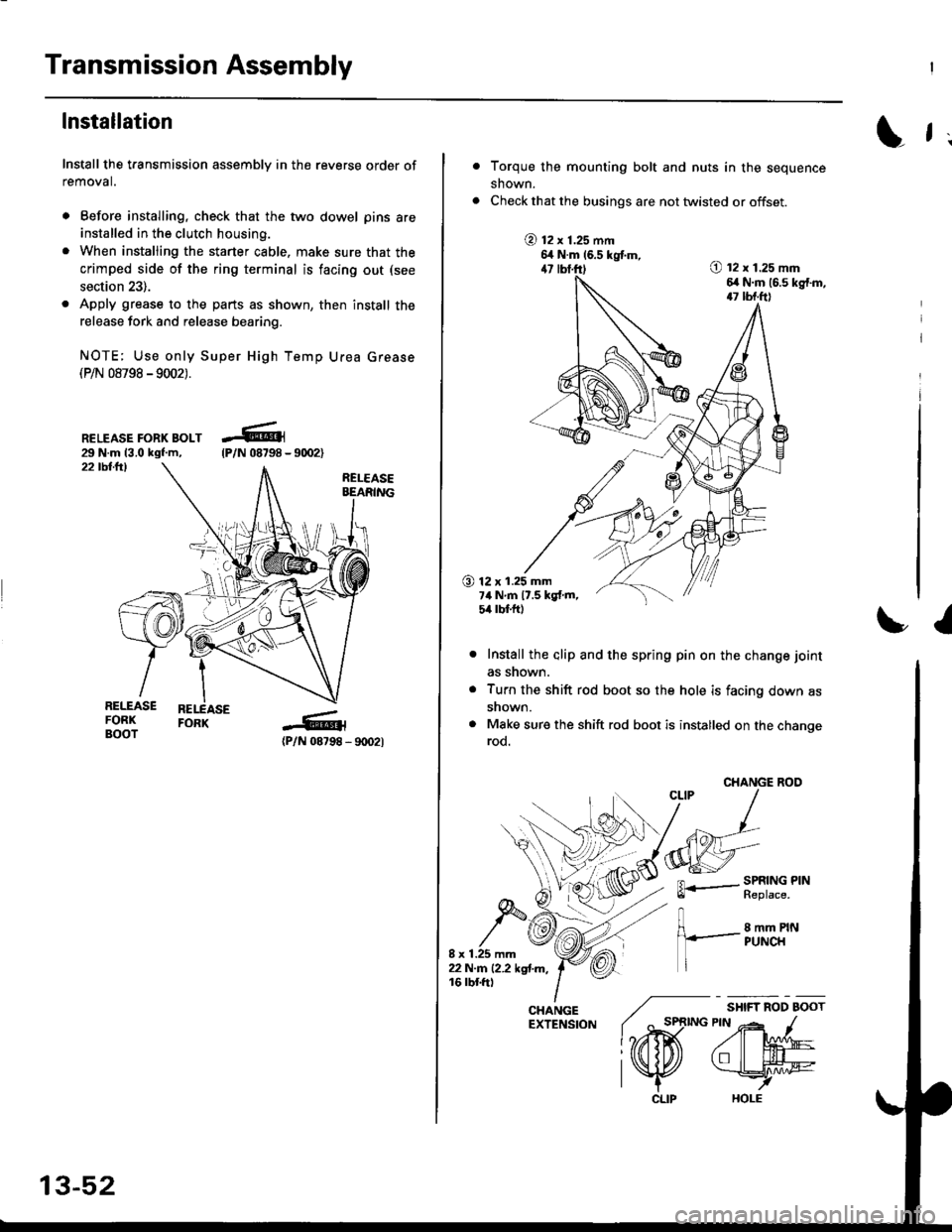
lnstallation
Install the transmission assembly in the reverse order of
removal.
. Before installing, check that the two dowel pins are
installed in the clutch housing.
. When installing the starter cable. make sure that the
crimped side of the ring terminal is facing out (see
section 23).
. Apply grease to the parts as shown, then install the
release fork and release bearing.
NOTE; Use only Super High Temp Urea Grease(P/N 08798 -9002).
RELEASE FORK BOLT29 N.m 13.0 kgf.m,22 tbllrl
(P/N 08798 - 9rD2l
-R1
tP/N 08798 -
13-52
CLIP
L f ;
Torque the mounting bolt and nuts in the sequence
shown.
Check that the busings are not twisted or offset.
@ t2 x 1.25 mm6,t N.m 16.5 kgtm,47 lbf.ft)O t2 x 1.25 mm6,r N.m (6.s kg{.m,17 tbf.ft)
O 12 x 1.25 mm7ilNm17.5kgf.m,5it lbt ft)
I
Install the alip and the spring pin on the change joint
as snown.
Turn the shift rod boot so the hole is facing down as
snown.
Make sure the shift rod boot is installed on the changerod.
CHANGE ROO
FL.- SPRING PINll heptace,
8 mm PINPUNCH
/ "*,*
lo,iD(
CHANGE ./EXTENSfoN ( ^ st
l?rffi
l\K
Page 635 of 2189
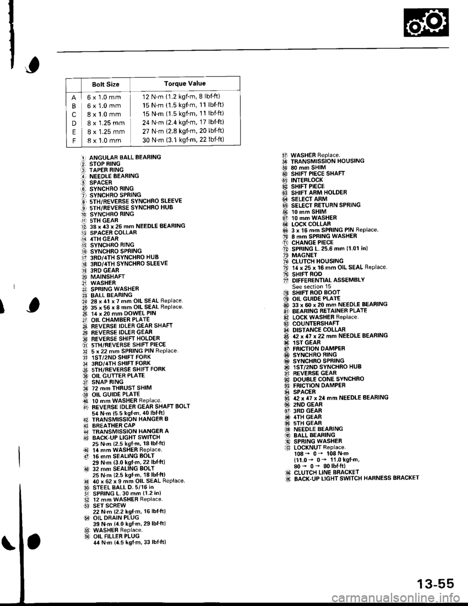
Bolt SizeTorque Value
cn
E
F
6x1.0mm
6x1.0mm
8 x 1.0 mm
8 x '1.25 mm
8 x 1.25 mm
8 x 1,0 mm
12 N.m (1.2 kgnm, 8 lbf'ft)
15 N.m (1.5 kgf'm, 11 lbf ft)
15 N.m (l.5 kgf.m, 11 lbift)
24 N'm (2.4 kgim, 17 lbift)
27 N.m (2.8 kgf.m,20 lbf'ft)
30 N.m (3.1 ksf m. 22 lbift)
5i WASHER Replace.6 TRANSMrssioN HouslNG!9 80 mm SHIM@ SHIFT PIECE SHAFT(6' INTERLOCK@ sHrFr PECE6} SHIFT ARM HOLDER@ seucr nnrvtI9 SELECT RETURN SPRING
@ 10 mm SHIM6, 10 mm WASHER@ LOCK COLLARi6sl 3 x l5 mm SPRING PIN Replace.t0 8 mm SPRING WASHERA) CHANGE PIECEll SPRING L.25.6 mm (1.01 in)'' MAGNET?4) CLUTCH HOUSINGta. 14 x 25 x 16 mm OIL SEAL Replace.A sHrFT BooO D|FFERENT|aL ASSEMBLYSee section 15iIO SHIFT ROD BOOT6 OIL GUIDE PLATE@ 33 x 60 x 20 mm NEEDLE BEASINGO BEARING RETAINER PLATElD LocK WASHER Replace..0 couNTERSHAFIA DISTANCE COLLAR6 & x 4I x 22 mm NEEDLE BEARING6. 1sr GEAR@ FRICTION DAMPERO SYNCHRO RING.d SYNCHRO SPRING@ 1ST/2ND SYNCHRO HUB..9i. REVERSE GEARC) DOUBLE CONE SYNCHROO FRICTION DAMPERS SPACER6 T2 x TI x 24 mm NEEDLE BEARING(!' 2ND GEAR61 3RD GEARiD 4TH GEAR@ 5TH GEAR(O NEEDLE BEARING(10 BALL BEARING@ SPRING WASHERf,o LoCKNUT Replace.108 - 0- 108 N'm111.0- 0* 11.0 kgf m,80* 0- 80lbI.ft)IO CLUTCH LINE BRACKET.d BACK.UP LTGHT SWITCH HARNESS BRACKET
:!, ANGULAR BALL BEABING:2, STOP RING:3] TAPER RING..-I NEEOLE BEARINGl!-- SPACERO SYNCHRO RING? SYNCHRO SPRINGE 5TH/REVERSE SYNCHRO SLEEVE...] sTH/REVERSE SYNCHRO HUB
O SYNCHBO EING.11-r sTH GEAR1A 38 x 43 x 26 mm NEEDLE BEARINGI13) SPACER COLLAR[!] /ITH GEAR.T5) SYNCHRO RING
O SYNCHRO SPRING17 3RD/4TH SYNCHRO HUB
O 3RD/4TH sYNcHRo SLEEVE
ii9 38D GEAR8I MAINSHAFT2i WASHERA SPRING WASH€R?I BALL BEARING.a4, 28 x 41 x 7 mm OIL SEAL Replace..2i 35 x 56 x 8 mm OIL SEAL Replace.t-t 14 x 20 mm DowEL PIN
.'] OIL CHAMBER PLATE
O REVERSE IDLER GEAR SHAFT.iI.., REVERSE IDLER GEAR'd REVERSE SHIFI HOLDERait srH/REVERSE sHIFT PIECE'34 5 x 22 mm SPRING PIN Replace.3' 1ST/2ND SHIFT FORK,34' 3RD/4TH SHIFT FORKi9t) srH/nevense sstrr ronx33 OIL GUTTER PLATE!' SNAP RING3d 72 mm THRUST SHIM
@ OIL GUIDE PLATE4t 10 mm WASHER Replaceti REVERSE TDLER GEAR SHAFT BoLT54 N.m {5.5 kgf m, 40lbIft)4N TBANSMISSION HANGER B43] BREATHER CAPA,J TRANSMISSION HANGER AIT' BACK-UP LIGHT SWITCH
I
25 N.m {2.5 kgl.m, 18lblftl14 mm WASHER RePlaceaO 14 mmtt 16 mm16 mm SEALING BOLT29 N.m (3.0 kgf m,22 lbf ft):4s) 32 mm SEALING BoLT25 N m 12.5 kgl m, 18 lbl'ft)40 x 62 x I mm OIL SEAL ReplaceSTEEL BALL D.5/15 iNSPRING L. 30 mm {1.2 in)12 mm WASHER Replace.SET SCREW22 N.m {2.2 kg{ m, 16 lbl ftlOIL DRAIN PLUG39 N.m {4.0 kgf m, 29lbtftlWASHER Replace.OIL FILLER PLUG4,t N.m {4.5 kgl m, 33 lblftl
.!rl00
@l
13-55