fork HONDA CIVIC 1996 6.G Owner's Guide
[x] Cancel search | Manufacturer: HONDA, Model Year: 1996, Model line: CIVIC, Model: HONDA CIVIC 1996 6.GPages: 2189, PDF Size: 69.39 MB
Page 807 of 2189
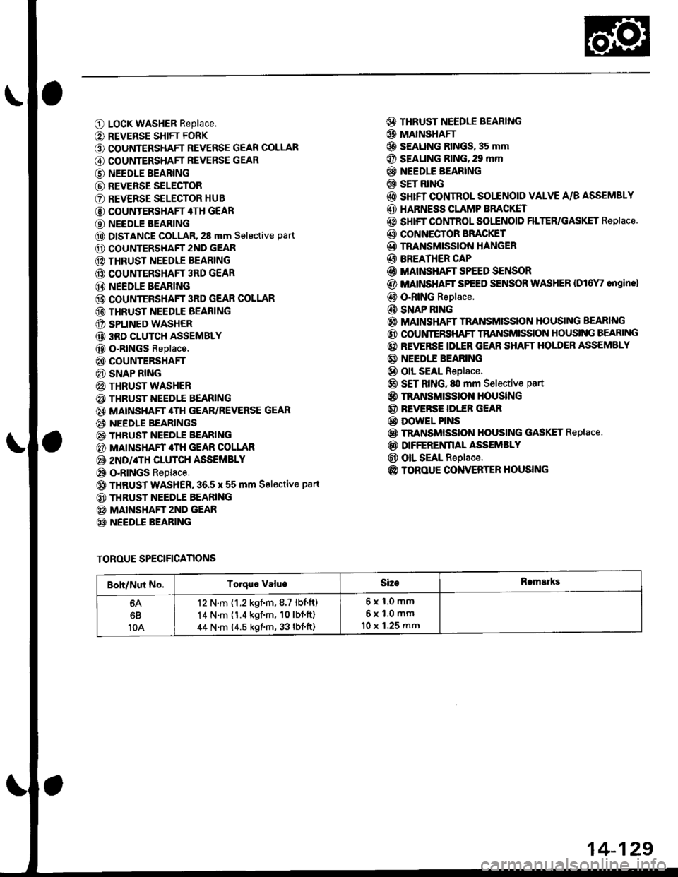
O LocK WASHER Replace,
O REVERSE SHIFT FORK
O COUNTERSHAFT REVERSE GEAR COLLAR
G) COUNTERSHAFT REVERSE GEAR
@ NEEDLE BEARING
@ REVERSE SELECTOR
O REVERSE SELECTOR HUB
@ COUNTERSHAFT 4TH GEAR
O NEEDLE BEARING
@ DISTANCE GOLLAR, 28 mm Selective part
O COUNTERSHAFT 2ND GEAR
@ THRUST NEEDIE BEARING
@ COUNTERSHAFT 3RD GEAR
@ NEEDLE BEARING
@ COUNTEBSHAFT 3RD GEAR COLLAR
@ THRUST NEEDLE BEAFING
O SPLINED WASHER
@ 3RD CLUTCH ASSEMBLY
@ O-RtNGs Replace.
@ COUNTERSHAFT
@ SNAP RING
@ THRUST WASHER
€) THRUST NEEDTE BEARING
@} MATNSHAFT 4TH GEAR/REVERSE GEAR
@i NEEDLE BEARINGS
@ THRUST NEEDLE EEARING
@) MAINSHAFT 4TH GEAR COLLAR
@ 2ND/4TH CLUTCH ASSEMBLY
@ o-RlNGs Replace.
@ THRUST WASHER,36.5 x 55 mm Sel€ctive part
@ THRUST NEEDLE BEARING
@ MAINSHAFT zND GEAR
@ NEEDLE BEARING
@ THRUST NEEDLE BEARING
@ MAINSHAFI
@ S€ALING RINGS, 35 mm
@ SEALING RING,29 mm
@} NEEDIE BEARING
@ SET RING
@ sHrFT CONTROL SOLENOID VALVE A/B ASSEMSLY
@ HARNESS CLAMP BRACKET
@ SHIFT COI,ITROL SOI"ENOID FILTER/GASKET Replace.
@ CONNECTOR BFACKET
@D TNANSMISSION HANGER
@ BREATHER CAP
@ MAINSHAFT SPEED SENSOR
@ MATNSHAFT SPEED SENSOR WASHER {Dl6Y' ongine}
@ O-RING Replace.
@ SNAP RING
@ MAINSHAFT TRANSMISSION HOUSING BEARING
@ OOUNIERSHAFT TRANSMISSION HOUSING BEARING
@ REVERSE IDLER GEAR SHAFT HOLDER ASSEMBLY
@ NEEDI.E BEARING
@ olL SEAL Replace.
@ SET RING, fll mm Selective part
@ rnANsMrssloN HouslNG
@ REVERSE IDI."ER GEAR
@ DowEL PINS
@ TRANSMISSION HOUSING GASKET Replace.
@ DIFFERENfIAL ASSEMBLY
@ OIL SEAL Replace.
@ TOROUE CONVERTER HOUSING
TOROUE SPECIFICANONS
Boh/Nut No.Torquo valueSizeRomarks
6B
10A
12 N.m {1.2 kgf.m,8.7 lbf.ft)
14 N.m (1.4 kgf'm, 10lbf'ft)
44 N.m (4.5 kgf.m, 33 lbf'ft)
6x1.0mm
6x1.0mm
10 x 1.25 mm
14-129
Page 856 of 2189
![HONDA CIVIC 1996 6.G Owners Guide Transmission
_\,]ffil
Reassembly (contd)
TRANSMISSIONHANGER
MAINSHAFTSUB.ASSEMBLY
*
Ufln
$*U ./
TRANSMISSION HOUSINGMOUNTING BOLTS10 x 1.25 mm4{ N.m {4.5 kg{.m,33 lbI.ft)
TRANSMISSION HOUSING
REVER HONDA CIVIC 1996 6.G Owners Guide Transmission
_\,]ffil
Reassembly (contd)
TRANSMISSIONHANGER
MAINSHAFTSUB.ASSEMBLY
*
Ufln
$*U ./
TRANSMISSION HOUSINGMOUNTING BOLTS10 x 1.25 mm4{ N.m {4.5 kg{.m,33 lbI.ft)
TRANSMISSION HOUSING
REVER](/img/13/6068/w960_6068-855.png)
Transmission
_\,]ffil
Reassembly (cont'd)
TRANSMISSIONHANGER
MAINSHAFTSUB.ASSEMBLY
*''
Ufln
$*U ./
TRANSMISSION HOUSINGMOUNTING BOLTS10 x 1.25 mm4{ N.m {4.5 kg{.m,33 lbI.ft)
TRANSMISSION HOUSING
REVERSE GEARCOLLAR
REVERSE GEAR
LOCK WASHER
SHIFT FORK
MAINSHAFT SPEEDSENSOR WASHER(D16Y7 engine)
MAINSHAFT
COUNTERSHAFTSUB.ASSEMBLY
OIFFER€NTIALASSEMBLY
SPEED
TRANSMISSIONHOUSING GASKET
TOROUE CONVERTERHOUSING
14-178
Page 857 of 2189
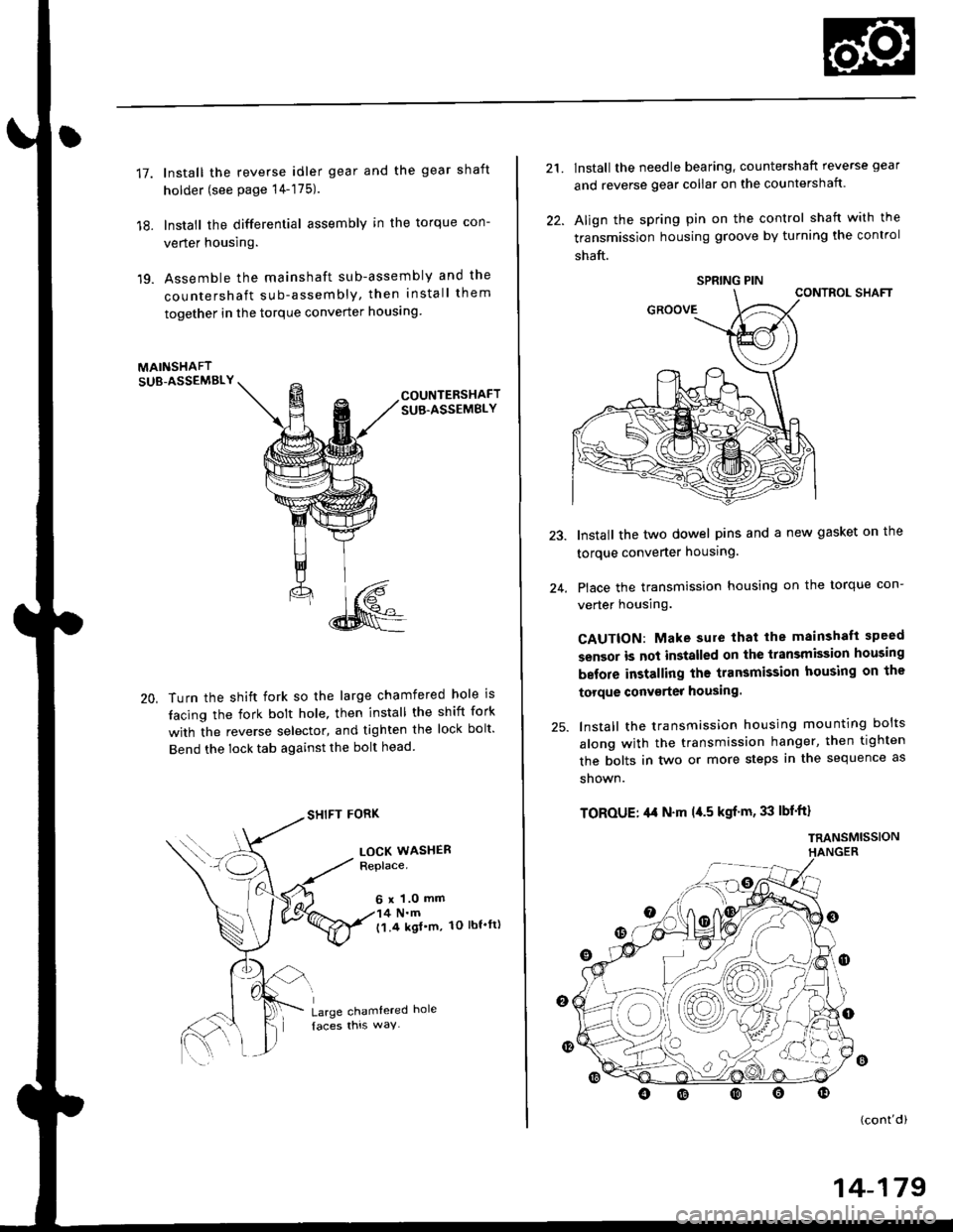
17.
18.
19.
lnstall the reverse idler gear and the gear shaft
holder (see page 14-175).
lnstall the differential assembly in the torque con-
verter housing.
Assemble the mainshaft sub-assembly and the
countershaft sub-assembly, then install them
together in the torque converter houslng
MAINSHAFTSUB-ASSEMBLY
20,
COUNTERSHAFTSUB.ASSEMBLY
Turn the shift fork so the large chamfered hole is
tacing the fork bolt hole, then install the shift fork
with the reverse selector, and tighten the lock bolt'
Bend the lock tab against the bolt head
SHIFT FORK
LOCK WASHERReplace.
6 x 1.0 mm4 N.m('l.4 kgl'm, 1O lbt'ft)
Large chamtered hole
21.
22.
lnstall the needle bearing, countershaft reverse gear
and reverse gear collar on the countershaft.
Align the spring pin on the control shaft with the
transmission housing groove by turning the control
shaft.
CONTROL SHAFT
Install the two dowel pins and a new gasket on the
torque converter housing.
Place the transmission housing on the torque con-
verter housing.
CAUTION: Make sure that lhe mainshaft speed
sensor is not installed on the transmission housing
before installing the transmission housing on the
torque conv€rter housing.
lnstall the transmission housing mounting bolts
along with the transmission hanger, then tighten
the bolts in two or more steps in the sequence as
shown.
TOROUE: ,l,t N'm l{.5 kgf'm, 33 lbf'ft}
TRANSMISSIONHANGER
24.
o
(cont'di
SPRING PIN
14-179
Page 863 of 2189
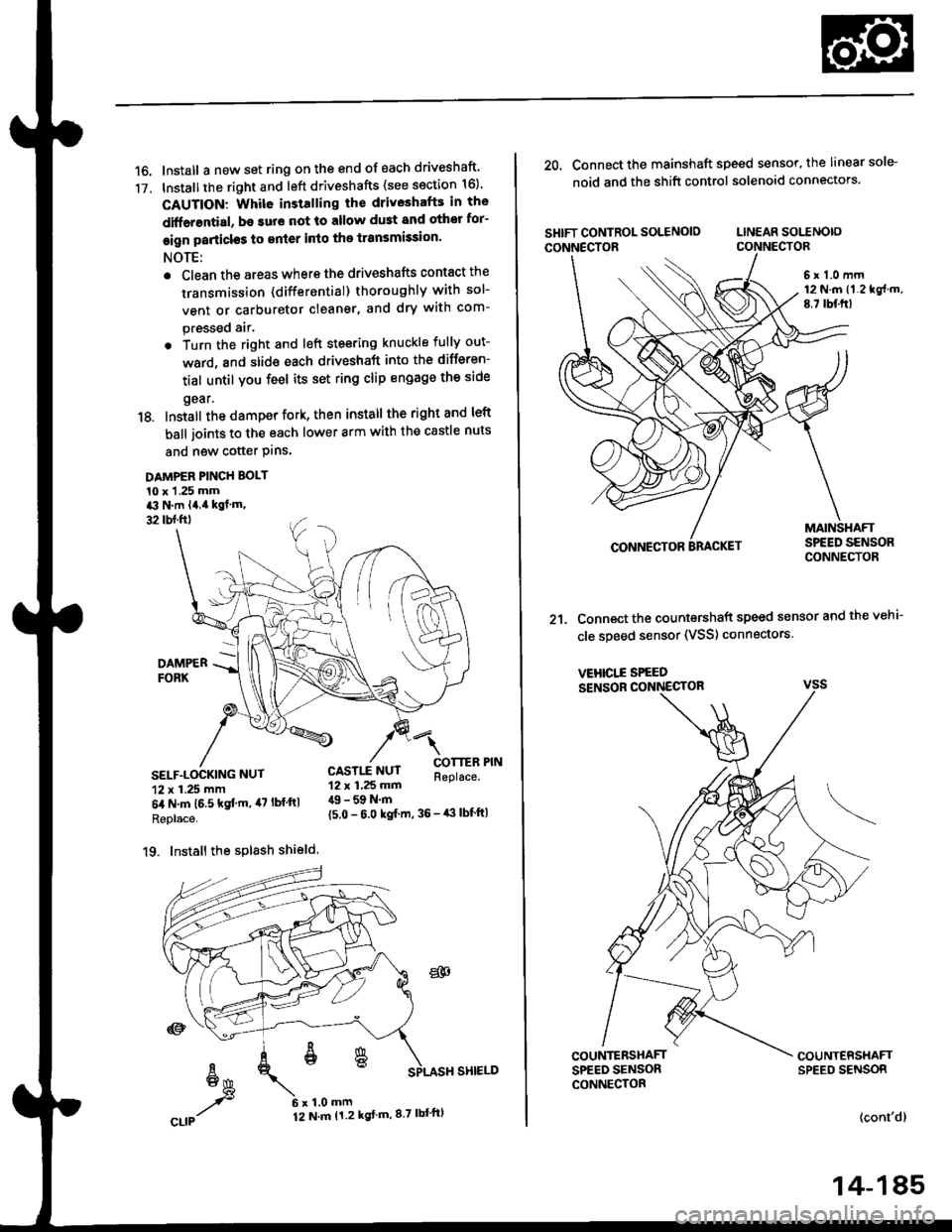
16. Install a new set ring on the end of each driveshaft'
17. Installthe right and left driveshafts (see ssction 16)
CAUTION: Whil6 installing the driveshafE in the
diffarential, be surs not lo allow du3t and othor for-
eign particl€s to enler into the transmission.
NOTE:
. Clean the areas where the driveshafts contact the
transmission (differential) thoroughly with sol-
vent or carburetor cleaner, and dry with com-
pressed air.
. Turn the right and left steering knuckle fully out-
ward, and slide each driveshaft into the differen-
tial until you feel its set ring clip engage the side
gear.
18. Install the damper fork, then install the rightand left
ball joints to the each lower arm with the castle nuts
and new cotter Plns.
DAMPER PINCH BOLT
10 x 1 .25 mma3 N.m l4.ia kgf.m,
32 tbl.ftl
4l
COTTERReplace.SELF.LOCKING NUT
12 x 1.25 mm
6il N.m t6.5 kgf'm, il7 lbf ftl
Replace.
19. Install the splash shield.
{5.0 - 6.0 kgf m, 36 - iB lbf'ft|
CASTLE NUT12 x 1,25 mm49 - 59 N.m
20. Connect the mainshaft speed sensor, the linear sole-
noid and the shift control solenoid connectors.
SHIFT CONTROL SOLENOIO LINEAR SOITNO|o
CONNECTOR CONNECTOR
6 r 1.0 mrn12 N.m (1.219f.m,
E.7 lbf.frl
CONNECTOR
21. Connect the countershaft speed sensor and the vehi-
cle speed sensor (VSS) connectors.
VEHICI..E SPEED
SENSOR CONNECTOR
COUNTERSHAFTSPEED SENSORCONNECTOR
(cont'dl
14-185
Page 983 of 2189
Transmission
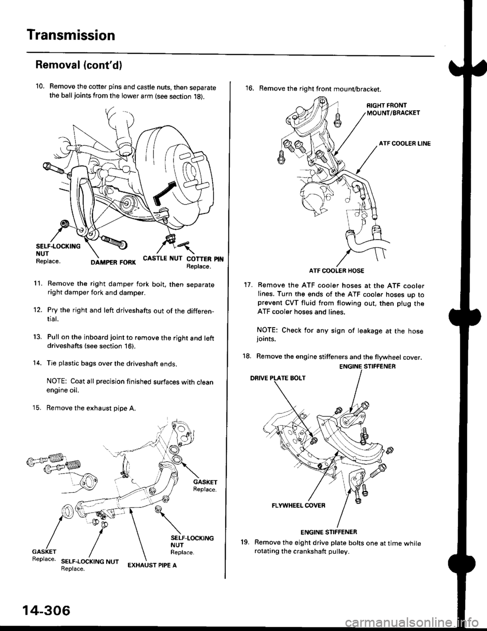
Removal (cont'd)
10. Remove the cotte. pins and castle nuts, then separatethe ball joints from the lower arm (see section 1g).
SELF-LOCKING -=V,
NUT \Replace. oitupea rOax
Remove the right damper fork bolt, then separateright damper fork and damper.
Pry the right and left driveshafts out of the differen-tial.
Pull on the inboard joint to remove the right and leftdriveshafts (see section 16).
Tie plastic bags over the driveshaft ends.
NOTE: Coat all precision finished surfaces with cleanengine oil.
Remove the exhaust pipe A.
/\<,\CASTLE I{UT COTTERReplac6.
't 1.
't2.
tJ.
14.
q.
SELF.LOCKINGNUTReplace.
SELF.LOCKING NUTReplace.
14-306
EXHAUST PIPE A
19.
'16, Remove the right front mounvbracket,
ATF COOLER HOSE
17. Remove the ATF cooler hoses at the ATF coolerlines. Turn the ends of the ATF cooler hoses uo toprevent CVT fluid from flowing out, then plug theATF cooler hoses and lines,
NOTE: Check for any sign of leakage at the hosejoints.
18. Remove the engine stiffeners and the flywheel cover.
Remove the eight drive plate bolts one at time whilerotating the crankshaft pullev.
ENGINE STIFFENER
Page 1026 of 2189
Transmission
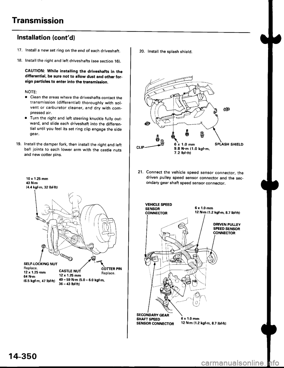
17.
Installation (cont'd)
Install I new set ring on the end of each driveshaft.
Install the right and left driveshafts (see section 16).
CAUTION: While instatling the drive3hafts in thedifferential, be sure not to allow dust and olher for-aign particles to enter into tho transmission.
NOTE:
. Clean the areas where the driveshafts contact thetransmission {differential} thoroughly with sol-vent or carburetor cleaner, and drv with com-
Dressed air.
. Turn the right and left steering knuckle fully out-wa.d, and slide each driveshaft into the differen-tial until you feel its set ring clip engage the sidegear.
Install the damper fork, then install the right and leftball joints to each lower arm with the castle outsand new cotter pins.
19.
10 x 1.25 mm43 N.m{4.4 kgf.m, 32 lbf.ftl
SELF-LOCKING NUTReplace.12 x 1.25 mm6l N.m
CASTI.I'12 x 1.25 mm
{6.s ksr.m. 47 tbr.ftr l! _ ll ffiteo
- s.o tet'.,
14-350
20. Install the splash shietd.
aa
I6I6*
"a,a s
21.
SECONOARY GEARSHAFT SPEEDSENSOB CONNECTOR
6 x 1.0 mm9.8 t{.m 11.0 kgt.m,7.2 tbf.trl
Connect the vehicle speed senso. connector. thedriven pulley speed sensor connector and the sec-ondary gear shaft speed sensor connector,
6x1,0mm12 N.m {1.2 kg{.m, 8.7 tbf,ft)
DRIVEN PULLEYSPEED SENSORCONNECTOR
E.
6 x 1.0 m.rl'12 N.m {1.2 kg{.m,8.7 tbf.fo
Page 1052 of 2189
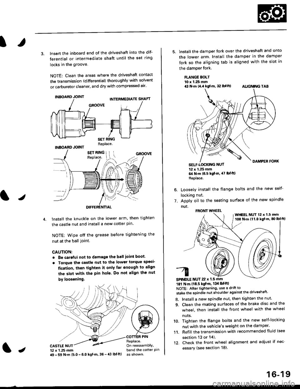
3. lnsert the inboard end of the driveshaft into the dif-
terential or intermediate shaft until the set ring
locks in the groove
NOTE: Clean the areas where the driveshaft contact
the transmission (differential) thoroughly with solvent
or carburetor cleaner, and dry with compressed air'
INBOARD JOINT
INBOARD JOINTReplace.
GROOVE
an
DIFFERENTIAL
lnstall the knuckie on the lower arm. then trghten
the castle nut and install a new cotter pin
NOTE: wipe off the grease before tightening the
nut at the ball ioint.
CAUTION:
. Be careful not to damago the ball ioint boot'
. Torque the castle nut to the lower torque sp€ci-
fication, thsn tighten it only far enough to align
the slot with th€ pin hol6. Do not align the nut
by loosening.
CASTLE NUT12 x 1 .25 mm
COTTER PINReplace.On reassemblY,bend the cotter pinJi$ - 59 N.m 15.0 - 6.0 kgl m,35 - 43 lbf ftl
16-19
5. lnstall the damper tork over the driveshaft and onto
the lower arm. Install the damper in the damper
fork so the aligning tab is aligned with the slot in
the damPer fork.
FLANGE BOLTl0 r 1.25 mmrit N.m t4.a kgf.m, 32 lbf.ft) AIIGN|NG TAB
1.
SELF-LOGKING NUT12 x 1.25 mm6,1N.m 16.5 kgi.m, a7 lbfftl
Replace.
Loosely install the flange bolts and the new self-
locking nut.
Apply oil to the seating surface of the new spindle
nut.
181 N m 118.5 kgt'm, 13il lbt'ftl
NOTE: Aftortightening, use a drift to
stake the spindle nut shoulder against the drivoshaft'
8. Install a new spindle nut, then tighten the nut'
9. Clean the mating surfaces ot the brake disc and the
wheel. then install the front wheel with the wheel
nuts.
10. Tighten the flange bolts and the new self-locking
nut with the vehicle's weight on the damper.
11. Refill the transmission with recommended fluid (see
section 13 or 14).'t2. Check the front wheel alignment and adjust if nec-
essary (see section 18),
FRONT WHEEL
SPINDLE NUT 22 x 1.5 mm
WHEEL NUT 12 x 1.5 mm108 N.m (11.0 kgl'm, g) lbl ftl
Page 1132 of 2189
Front Suspension
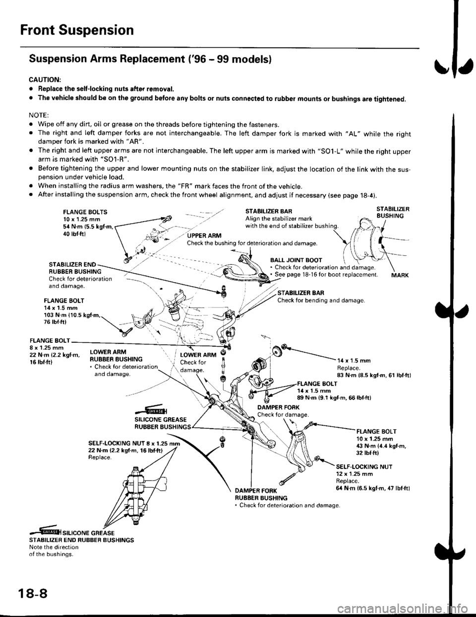
Suspension Arms Replacement ('96 - 99 models)
CAUTION:
. Replace the selt-locking nuts after removal.
. The vehicle should be on the ground betore any bolts or nuts connected to rubber mounts or bushings are tightened.
NOTE:
. Wipe off any dirt, oil or grease on the threads before tightening the fasteners.. The right and left damper forks are not interchangeable. The left damper fork is marked with "AL" while the rightdamper fork is marked with "AR'
. The right and left upper arms are not interchangeable. The left upper arm is marked with "SO1-L" while the right upperarm is marked with "SOl-R".
. Before tightening the upper and lower mounting nuts on the stabilizer link, adjust the location of the link with the sus-pension under vehicle load.
. When installing the radius arm washers, the "FR" mark faces the front ofthe vehicle.. After installing the suspension arm, ch eck the front wheel alignment, and adjust if necessary (see page 18-4).
FLANGE BOLTS10 x 1.25 mm54 N.m 15.5 kgl.m,40 tbf.ftl
STAEILIZER ENDRUBBER BUSHING
BALL JOINT BOOT. Check for deterioration and damage.. See page 18-16 for boot replacement.
STABILIZER BARCheck for bending and damage.
Check for deterioration - ---\--
and damage, -\
FLANGE BOLT14 x 1.5 mm/)l103 N.m {10.5 kg{.m,. t, ,/4,76lb{.ft) t,,"-iV
v:\FLANGE BOLT-
;iffillr-"- ilHitffi*::,"*"
and damaoe,
o.'-----------14 x 1.5 mmReplace.83 N.m {8.5 kgf.m, 61 lbf.ftl
LOWER ARMCheck for
c
JlTTda
1{ x 1.5 mm89 N.m {9.1 kgt m. 66 lbtft)
-6;SILICONE GREASERUBBER BUSHING
DAMPER FORKCheck for damage.
SELF-LOCKING NUT I x 1.2522 N.m (2.2 kg{.m, 16lbf.ftlReplace.
FLANGE BOLT10 x 1.25 mm€ N.m {4.6 kgt m.32 tbf.ft)
SELF-LOCKING NUT12x 1.25 mmReplace.6it N m {6.5 kgf.m, 47 lbf.ftl
RUEBER BUSHING. Check for deterioration and damage.
.6t",.,"o".c"KeSTAAIL|zER END RUBBER EUSHINGSNote the directionof the bushings.
18-8
Page 1133 of 2189
I
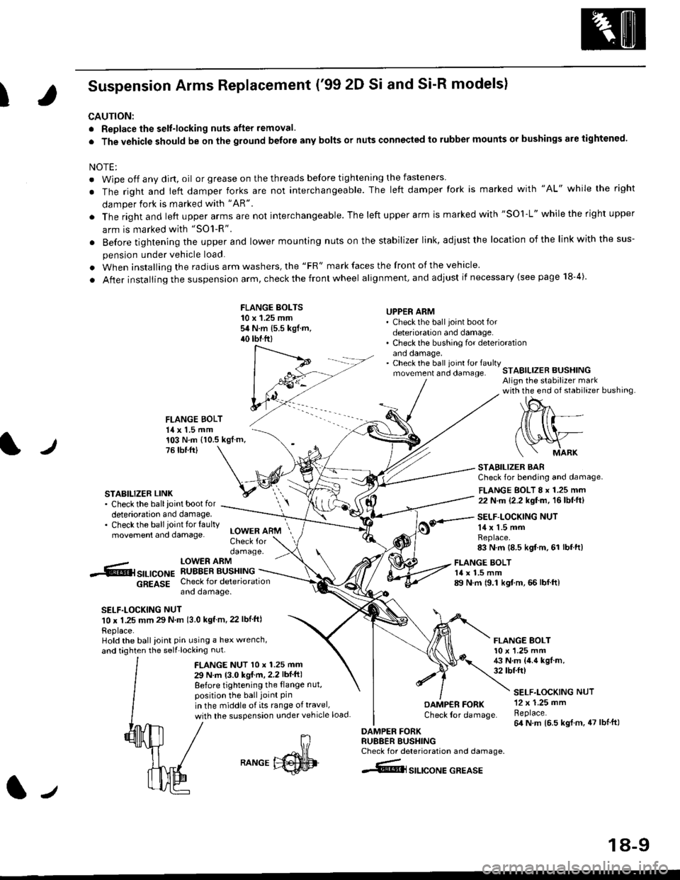
Suspension Arms Replacement ('99 2D Si and Si-R models)
CAUTION:
. Replace the selt-locking nuts after removal.
. The vehicle should be on the ground belore any bolts or nuts connected to rubber mounts or bushings are tightened.
NOTE:
. Wipe off any dirt, oil or grease on the threads before tightening the fasteners
. The right and ieft damper forks are not interchangeable. The left damper fork is marked with "AL" while the right
damper fork is marked with "AR"
. The right and left upper arms are not interchangeable. The left upper arm is marked with "SOl-L" while the right upper
arm is marked with "SO1-R".
. Before tightening the upper and lower mounting nuts on the stabilizer link, adiust the location of the link with the sus-
pension under vehicle load.
. When installing the radius arm washers, the "FR" mark faces the front of the vehicle.
. After installing the suspension arm, check the front wheel alignment, and adjust if necessary (see page 18-4).
FLANGE BOLTS10 x 1.25 mmsit N.m 15.5 kgf.m,40 tbtftl
UPPER ARM' Check the ball joint boot fordeterioration and damage.. Check the bushing for deteriorationano oamage,. Check the ball ioint fo. faultymovement and clamage.STABILIZER BUSHINGAlign the stabilizer markwith the end of stabilizer bushing
FLANGE BOLT14 x 1.5 mm
l./
103 N.m (10.5 kgf.m,76 tbr.ftl
STABILIZER LINK. Check the ballioint bootfordeterioration and damage.. Checkthe ballioint tor faultymovement and damage.
STABILIZER BARCheck for bending and damage.
FLANGE BOLT 8 x 1.25 mm22 N.m (2.2 kgf.m, 16lbf.ft)
SELF-LOCKING NUT14 x 1.5 mmReplace.83 N.m 18.5 kgf m, 61 lbf.ft)
-.6r srr-,co", hSHrtlrT.[*"u
6g619g Check for deteriorationano oamage.
SELF.LOCKING NUT10 x 1.25 mm 29 N m 13.0 kgf m, 22 lbf ftl
Replace.Hold the ball ioint pin using a hex wrench,
and taghten the self'locking nut.
LOWER ARMCheck fordamage.
FLANGE NUT l0 x 1.25 mm
29 N.m 13.0 kgI m,2.2 lbf ft)
Before tightening the {lange nut,position the ball joint Pinin the middle of its range of travel,
with the suspension under vehicle load
FLANGE BOLT14 x 1.5 mm89 N.m 19.1 kgf.m, 66 lbf.ft)
FLANGE BOLT10 x '1.25 mm43 N.m {4.4 kgf.m,32 tbtft)
DAMP€R FORKCheck lor damage.
DAMPER FORKRU88ER BUSHINGCheck for deterioration and damage.
4@lsrlrcoNE GREASE
SELF.LOCKING NUT12 x 1.25 mmReplace.64 N m 16.5 kgl.m, 47 lblft)
J
RANGE
18-9
Page 1141 of 2189
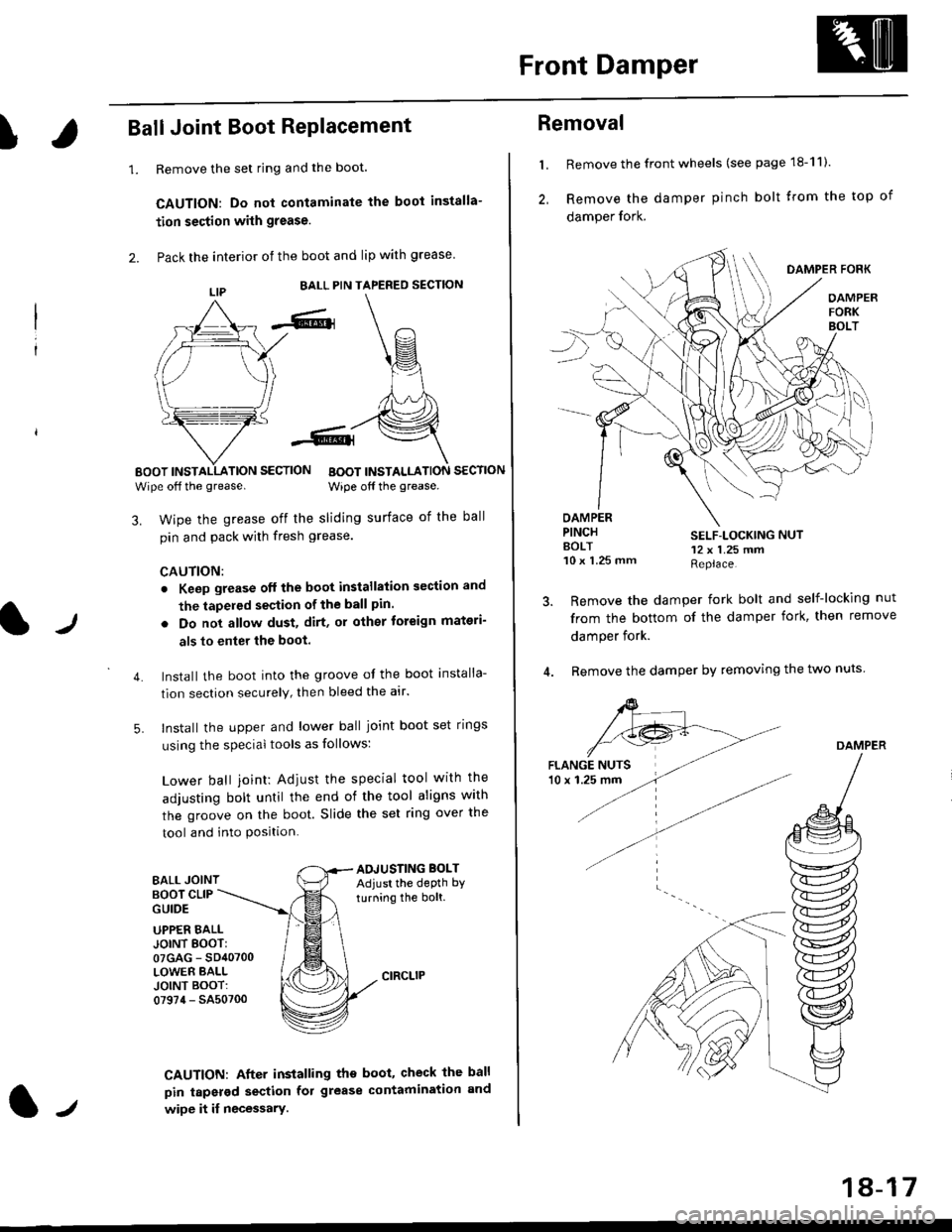
Front Damper
!Ball Joint Boot RePlacement
1.Remove the set ring and the boot.
CAUTION: Do not contaminate the boot installa-
tion section with grease.
Pack the interior of the boot and lip with grease
EALL PIN TAPERED SECTION
EOOT INSTALLATION SECTION
Wipe off the grease.BOOT INSTALLATION SECTION
Wipe off the grease.
lJ
3. Wipe the grease off the sliding surface of the ball
pin and pack with fresh grease.
CAUTION:
. Keep grease off the boot installation section and
the tapeled section of the ball pin.
5.
. Do not allow dust, dirt, or other toreign materi-
als to enter the boot.
Install the boot into the groove of the boot installa-
tion section securely, then bleed the atr.
Install the upper and lower ball joint boot set rings
using the special tools as follows:
Lower ball joint: Adiust the special tool with the
adjusting bolt until the end of the tool aligns with
the groove on the boot. Slide the set ring over the
tool and into Position.
BALL JOINTAOJUSTING BOLTAdjust the depth by
turning the bolt.BOOT CLIPGUIDE
4.
UPPER EALLJOINT EOOT:07GAG - SD40700LOWER BALLJOINT BOOT:07974 - SA50700
CAUTION: After installing the boot, check the ball
pin tapsrod section fol grease contamination and
wipe it if necessary.lt
18-17
Removal
l. Remove the front wheels (see page 18-11).
2, Remove the damper pinch bolt trom the top of
damper fork.
DAMPER FORK
OAMPERFORKBOLT
OAMPERPINCHAOLT10 x 1.25 mm
SELF-LOCKING NUT12 x 1.25 mmReplace.
Remove the damper fork bolt and self-locking nut
from the bottom of the damper fork, then remove
damper fork.
Remove the damper by removing the two nuts
DAMPER